EP0078201A1 - Ensemble de freinage de vis - Google Patents
Ensemble de freinage de vis Download PDFInfo
- Publication number
- EP0078201A1 EP0078201A1 EP82401922A EP82401922A EP0078201A1 EP 0078201 A1 EP0078201 A1 EP 0078201A1 EP 82401922 A EP82401922 A EP 82401922A EP 82401922 A EP82401922 A EP 82401922A EP 0078201 A1 EP0078201 A1 EP 0078201A1
- Authority
- EP
- European Patent Office
- Prior art keywords
- screw
- washer
- orifice
- head
- assembly according
- Prior art date
- Legal status (The legal status is an assumption and is not a legal conclusion. Google has not performed a legal analysis and makes no representation as to the accuracy of the status listed.)
- Granted
Links
Images
Classifications
-
- F—MECHANICAL ENGINEERING; LIGHTING; HEATING; WEAPONS; BLASTING
- F16—ENGINEERING ELEMENTS AND UNITS; GENERAL MEASURES FOR PRODUCING AND MAINTAINING EFFECTIVE FUNCTIONING OF MACHINES OR INSTALLATIONS; THERMAL INSULATION IN GENERAL
- F16B—DEVICES FOR FASTENING OR SECURING CONSTRUCTIONAL ELEMENTS OR MACHINE PARTS TOGETHER, e.g. NAILS, BOLTS, CIRCLIPS, CLAMPS, CLIPS OR WEDGES; JOINTS OR JOINTING
- F16B21/00—Means for preventing relative axial movement of a pin, spigot, shaft or the like and a member surrounding it; Stud-and-socket releasable fastenings
- F16B21/10—Means for preventing relative axial movement of a pin, spigot, shaft or the like and a member surrounding it; Stud-and-socket releasable fastenings by separate parts
- F16B21/16—Means for preventing relative axial movement of a pin, spigot, shaft or the like and a member surrounding it; Stud-and-socket releasable fastenings by separate parts with grooves or notches in the pin or shaft
- F16B21/18—Means for preventing relative axial movement of a pin, spigot, shaft or the like and a member surrounding it; Stud-and-socket releasable fastenings by separate parts with grooves or notches in the pin or shaft with circlips or like resilient retaining devices, i.e. resilient in the plane of the ring or the like; Details
- F16B21/183—Means for preventing relative axial movement of a pin, spigot, shaft or the like and a member surrounding it; Stud-and-socket releasable fastenings by separate parts with grooves or notches in the pin or shaft with circlips or like resilient retaining devices, i.e. resilient in the plane of the ring or the like; Details internal, i.e. with spreading action
-
- F—MECHANICAL ENGINEERING; LIGHTING; HEATING; WEAPONS; BLASTING
- F16—ENGINEERING ELEMENTS AND UNITS; GENERAL MEASURES FOR PRODUCING AND MAINTAINING EFFECTIVE FUNCTIONING OF MACHINES OR INSTALLATIONS; THERMAL INSULATION IN GENERAL
- F16B—DEVICES FOR FASTENING OR SECURING CONSTRUCTIONAL ELEMENTS OR MACHINE PARTS TOGETHER, e.g. NAILS, BOLTS, CIRCLIPS, CLAMPS, CLIPS OR WEDGES; JOINTS OR JOINTING
- F16B39/00—Locking of screws, bolts or nuts
- F16B39/02—Locking of screws, bolts or nuts in which the locking takes place after screwing down
- F16B39/10—Locking of screws, bolts or nuts in which the locking takes place after screwing down by a plate, spring, wire or ring immovable with regard to the bolt or object and mainly perpendicular to the axis of the bolt
Definitions
- the present invention relates to a screw braking assembly whose head is housed in an orifice provided for this purpose in the room where the screw is introduced.
- the object of the invention is to obviate these drawbacks by means of a combination making it possible to simultaneously ensure effective braking of the screw and retention of the screw head in the event of the latter breaking.
- the head of the screw being housed in an orifice provided for this purpose in the room where the screw is inserted, this orifice assumes the shape of a truncated cone whose apex is directed towards the head of the screw , and an elastically deformable washer. in the radial direction is introduced into this orifice after fitting the screw to come to bear against the head of the latter, the outside diameter of this washer being substantially equal to that of the base of the cone.
- this washer also has a frustoconical shape complementary to that of the orifice. It can be constituted by a ring cut along a radius, in which two holes are made symmetrically with respect to this radius so as to allow the introduction of the two points of a tool for placing the washer, a tool affecting the shape. of a compass.
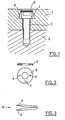
- Figure 1 shows, in cross section, a braking assembly according to the invention.
- FIG. 9 represents, in section and top view, the washer used in the assembly of FIG. 1, and,
- Figure 3 shows schematically a tool for the establishment of this washer.
- the part 1 must be assembled to the part 2 by screwing.
- a screw 3 for example with a flat head 4, is used.
- An orifice 5 is made in the part 1 so as to have the shape of a truncated cone, the apex of which is directed in the same direction as the head 4 of the screw 3 relative to the latter.
- a washer 6 is introduced into the orifice 5, a washer which is applied against the head 4 under the effect of the shape of the orifice 5.
- the washer 6 is elastically deformable in the direction radial. As shown in FIG. 2, for this purpose, the washer which consists of a ring is cut along one of the spokes 7.
- a very simple tool 10, as shown in FIG. 3, and affecting the shape of a compass, can then be used for the introduction of the washer 6 into the orifice 5.
- the two points 11 and 12 of this compass, introduced respectively in the holes 8 and 9 of the washer 6, allow the latter to be manually deformed, so as to elastically reduce its diameter during the operation consisting in its introduction into the orifice 5.
- the edge of the washer 6 comes in contact with the conical wall of the orifice 5 and, by reaction, the washer comes to apply naturally against the head 4 of the screw, thus ensuring its braking and its maintenance in the event of rupture.
- Tool 10 affecting the shape of a compass can be replaced by pliers of any type.
- the washer 6 can be of flat shape as shown, or else of concave or convex shape.
- the screw braking assembly according to the invention which finds its preferred application in the field of pumps for nuclear reactors, can be used in the manner of conventional devices in all fields, in particular when there is room to house them. is missing and the screw head must be retained in the event of a break.
Landscapes
- Engineering & Computer Science (AREA)
- General Engineering & Computer Science (AREA)
- Mechanical Engineering (AREA)
- Bolts, Nuts, And Washers (AREA)
- Connection Of Plates (AREA)
Abstract
Description
- La présente invention concerne un ensemble de freinage de vis dont la tête est logée dans un orifice prévu à cet effet dans la pièce où la vis est introduite.
- On connait de nombreux dispositifs et procédés permettant de freiner une vis, c'est à dire de l'empêcher de se dévisser sous l'effet de sollicitations vibratoires ou de dilatations thermiques. Le procédé le plus simple consiste à effectuer le collage de la vis dans la pièce où elle est introduite au niveau des filets. Il est connu également de disposer entre la pièce et la tête de la vis une rondelle déformable qui s'écrase élastiquement en maintenant la vis sous tension. Ces dispositif et procédé présentent toutefois l'inconvénient de ne pas être toujours très fiables et de ne pas retenir la tête de la vis en cas de rupture de celle-ci.
- On sait en effet qu'il est indispensable que la tête des vis soit retenue même en cas de rupture, notamment dans l'industrie nucléaire lorsqu'elles équipent des pompes primaires. Dans ce but, on utilise souvent une coupelle qui est sertie après pliage dans la pièce où la vis est introduite. Toutefois cette solution présente l'inconvénient d'une mise en place -lorsqu'elle est possible- relativement longue, en particulier si on se réfère aux problèmes d'irradiation ou de contamination chimique dans l'industrie nucléaire et d'une pollution éventuelle du circuit dans lequel est disposé ce frein par des morceaux de la coupelle déformée plastiquement.
- L'invention a pour but d'obvier à ces inconvénients au moyen d'une combinaison permettant d'assurer simultanément un freinage efficace de la vis et une retenue de la tête de vis en cas de rupture de cette dernière.
- Selon l'invention, la tête de la vis étant logée dans un orifice prévu à cet effet dans la pièce où est introduite la vis, cet orifice affecte la forme d'un tronc de cône dont le sommet est dirigé vers la tête de la vis, et une rondelle déformable élastiquement .dans le sens radial est introduite dans cet orifice après mise en place de la vis pour venir s'appliquer contre la tête de cette dernière, le diamètre extérieur de cette rondelle étant sensiblement égal à celui de la base du cône.
- De préférence, cette rondelle affecte également une forme tronconique complémentaire de celle de l'orifice. Elle peut être constituée par un anneau coupé selon un rayon, dans lequel deux trous sont pratiqués symétriquement par rapport à ce rayon de manière à permettre l'introduction des deux pointes d'un outil de mise en place de la rondelle, outil affectant la forme d'un compas.
- L'invention sera mieux comprise et d'autres buts, avantages et caractéristiques de celle-ci apparaîtront plus clairement à la lecture de la description qui suit d'un mode préféré de réalisation, description à laquelle une planche de dessins est annexée.
- La Figure 1 représente, en coupe transversale, un ensemble de freinage conformément à l'invention.
- La Figure 9 représente, vue en coupe et vue en dessus, la rondelle utilisée dans l'ensemble de la Figure 1, et,
- la Figure 3 représente schématiquement un outil pour la mise en place de cette rondelle.
- En référence maintenant à ces figures, la pièce 1 doit être assemblée à la pièce 2 par vissage. Dans ce but, on utilise une vis 3, par exemple à tête plate 4.
- Un orifice 5 est pratiqué dans la pièce 1 de manière à affecter la forme d'un tronc de cône dont le sommet est dirigé dans le même sens que la tête 4 de la vis 3 par rapport à cette dernière.
- Après vissage, on introduit une rondelle 6 dans l'orifice 5, rondelle qui vient s'appliquer contre la tête 4 sous l'effet de la forme de l'orifice 5. Pour ce faire, la rondelle 6 est déformable élastiquement dans le sens radial. Comme représenté figure 2, dans ce but, la rondelle qui est constituée par un anneau est coupée selon un des rayons 7.
- En donnant à cette rondelle une forme tronconique sur sa tranche, on lui permet de s'appliquer avec une force importante sur la tête 4 de la vis 3 qui est alors prise en sandwich entre la pièce 1 et la rondelle 6.
- Les forces de frottement exercée empêchent alors la vis 3 de se dévisser et ces forces sont d'autant plus importantes que la vis commence à se deserrer du fait de la forme de l'orifice 5. En outre, cette forme présente l'avantage essentiel de permettre à la rondelle 6 de retenir la tête 4 de la vis 3, en cas de rupture de cette dernière. La tête ne sort donc pas de l'orifice 5 et ne risque ainsi pas de venir perturber inopportunément le fonctionnement du matériel qu'elle équipe.
- Cependant une telle rondelle, dont le diamètre extérieur est sensiblement égal à celui de la base du cône de l'orifice 5, peut être délicate à introduire dans un orifice dont l'embouchure présente un diamètre plus petit. Pour pallier à cet inconvénient, deux trous 8 et 9 sont pratiqués dans la rondelle qui affecte la forme d'un anneau, symétriquement par rapport à la coupure radiale 7.
- Un outil très simple 10, tel que représenté Figure 3, et affectant la forme d'un compas, peut être alors utilisé pour l'introduction de la rondelle 6 dans l'orifice 5. Les deux pointes 11 et 12 de ce compas, introduites respectivement dans les trous 8 et 9 de la rondelle 6, permettent de déformer manuellement cette dernière, de manière à réduire élastiquement son diamètre pendant l'opération consistant en son introduction dans l'orifice 5. Après introduction, la tranche de la rondelle 6 vient en contact avec la paroi conique de l'orifice 5 et, par réaction, la rondelle vient s'appliquer naturellement contre la tête 4 de la vis, assurant ainsi son freinage et son maintien en cas de rupture. Bien que seul un mode de réalisation de l'invention ait été décrit, il est évident que toute modification apportée par l'Homme de l'Art dans le même esprit ne sortirait pas du cadre de la présente invention. Notamment, on peut disposerentre la tête 4 de la vis et la pièce 1 une rondelle élastique compressible comme dans l'Art antérieur, ce qui rend le freinage de la vis extrêmement sûr. En outre, même si la vis représentée est une vis à tête plate dont on n'a pas représenté le nombre de pans, cet ensemble de freinage peut être utilisé avec n'importe quel type de vis.
- L'outil 10 affectant la forme d'un compas peut être remplacé par une pince de n'importe quel type. Enfin la rondelle 6 peut être de forme plate telle que représentée, ou bien de forme concave ou convexe.
- L'ensemble de freinage de vis selon l'invention, qui trouve son application préférée dans le domaine des pompes des réacteurs nucléaires, peut être utilisé à la manière des dispositifs conventionnels dans tous les domaines, en particulier lorsque la place pour loger ceux-ci fait défaut et que la tête de la vis doit être retenue en cas de rupture.
Claims (4)
Applications Claiming Priority (2)
| Application Number | Priority Date | Filing Date | Title |
|---|---|---|---|
| FR8119753A FR2514843A1 (fr) | 1981-10-21 | 1981-10-21 | Ensemble de freinage de vis |
| FR8119753 | 1981-10-21 |
Publications (2)
| Publication Number | Publication Date |
|---|---|
| EP0078201A1 true EP0078201A1 (fr) | 1983-05-04 |
| EP0078201B1 EP0078201B1 (fr) | 1986-07-30 |
Family
ID=9263240
Family Applications (1)
| Application Number | Title | Priority Date | Filing Date |
|---|---|---|---|
| EP19820401922 Expired EP0078201B1 (fr) | 1981-10-21 | 1982-10-20 | Ensemble de freinage de vis |
Country Status (3)
| Country | Link |
|---|---|
| EP (1) | EP0078201B1 (fr) |
| DE (1) | DE3272349D1 (fr) |
| FR (1) | FR2514843A1 (fr) |
Cited By (1)
| Publication number | Priority date | Publication date | Assignee | Title |
|---|---|---|---|---|
| EP0459028A1 (fr) * | 1990-05-29 | 1991-12-04 | Combustion Engineering, Inc. | Méthode de rÀ©paration d'un assemblage nucléaire comprenant un boulon avec un élément déformable de retenue |
Families Citing this family (1)
| Publication number | Priority date | Publication date | Assignee | Title |
|---|---|---|---|---|
| DE3640521C2 (de) * | 1986-11-27 | 1997-04-30 | Rexroth Pneumatik Mannesmann | Vorrichtung zur Sicherung eines stiftähnlichen Bauteiles, insbesondere einer Kopfschraube |
Citations (2)
| Publication number | Priority date | Publication date | Assignee | Title |
|---|---|---|---|---|
| DE90546C (fr) * | ||||
| DE2739644A1 (de) * | 1976-09-21 | 1978-03-23 | Andritz Ag Maschf | Schraubensicherung |
-
1981
- 1981-10-21 FR FR8119753A patent/FR2514843A1/fr active Granted
-
1982
- 1982-10-20 DE DE8282401922T patent/DE3272349D1/de not_active Expired
- 1982-10-20 EP EP19820401922 patent/EP0078201B1/fr not_active Expired
Patent Citations (2)
| Publication number | Priority date | Publication date | Assignee | Title |
|---|---|---|---|---|
| DE90546C (fr) * | ||||
| DE2739644A1 (de) * | 1976-09-21 | 1978-03-23 | Andritz Ag Maschf | Schraubensicherung |
Cited By (1)
| Publication number | Priority date | Publication date | Assignee | Title |
|---|---|---|---|---|
| EP0459028A1 (fr) * | 1990-05-29 | 1991-12-04 | Combustion Engineering, Inc. | Méthode de rÀ©paration d'un assemblage nucléaire comprenant un boulon avec un élément déformable de retenue |
Also Published As
| Publication number | Publication date |
|---|---|
| FR2514843B1 (fr) | 1985-01-25 |
| EP0078201B1 (fr) | 1986-07-30 |
| FR2514843A1 (fr) | 1983-04-22 |
| DE3272349D1 (en) | 1986-09-04 |
Similar Documents
| Publication | Publication Date | Title |
|---|---|---|
| EP0723103B1 (fr) | Dispositif de raccordement rapide d'un tube à un élément rigide | |
| EP1427959B1 (fr) | Dispositif de raccordement instantane | |
| CA1289124C (fr) | Dispositif d'etancheite flexible, pour un obturateur du type papillon | |
| EP0097545B1 (fr) | Butee se fixant dans un alesage d'un dispositif | |
| WO1996017201A1 (fr) | Dispositif de raccordement rapide d'un tube a un embout rigide | |
| EP2387681A1 (fr) | Dispositif d'ancrage d'un element dans une ouverture d'une paroi et raccord equipe d'un tel dispositif | |
| WO2001094798A1 (fr) | Insert d'implantation d'un raccord de tube dans un logement taraude | |
| EP1780427B1 (fr) | Rondelle d'ancrage non agressive | |
| WO2001009546A1 (fr) | Embout de protection pour une extremite de tube | |
| EP0078201B1 (fr) | Ensemble de freinage de vis | |
| FR2753383A1 (fr) | Raccord d'accouplement destine a relier un tuyau a un instrument medical, un appareil ou un autre tuyau | |
| EP0072345A1 (fr) | Boîte de montre | |
| FR2758379A1 (fr) | Cartouche d'implantation pour un raccord d'un tuyau destine a prendre place dans un logement | |
| EP0402223B1 (fr) | Cheville d'ancrage dans un trou à contre-dépouille | |
| EP0068971B1 (fr) | Voyant indicateur de niveau d'un liquide contenu dans une enceinte close, et cuve de compresseur hermétique munie d'un tel voyant | |
| EP0079291B1 (fr) | Ensemble d'écrous freinés à double freinage | |
| FR2787010A1 (fr) | Perfectionnements aux dispositifs d'implants dentaires | |
| EP0616164B1 (fr) | Joint d'étanchéité pour raccord à connexion instantanée à griffe ou à pince | |
| EP0526405A1 (fr) | Procédé de formation d'une retenue d'une pièce circulaire dans une pièce tubulaire | |
| EP1686306B1 (fr) | Dispositif de raccordement auto-extractible | |
| EP0207833A1 (fr) | Bouton fileté à limiteur de couple | |
| FR2663394A1 (fr) | Dispositif obturateur a bille libre a jeux regles. | |
| EP0085010A2 (fr) | Coupleur auto-obturateur, notamment pour fluide ou réfrigérant | |
| EP3867557B1 (fr) | Ensemble comprenant une canalisation et un dispositif de raccordement pour realiser le piquage d'un tube sur une paroi de la canalisation | |
| FR2729736A1 (fr) | Dispositif de raccordement rapide d'un tube a un element rigide |
Legal Events
| Date | Code | Title | Description |
|---|---|---|---|
| PUAI | Public reference made under article 153(3) epc to a published international application that has entered the european phase |
Free format text: ORIGINAL CODE: 0009012 |
|
| AK | Designated contracting states |
Designated state(s): BE CH DE FR GB LI |
|
| 17P | Request for examination filed |
Effective date: 19830912 |
|
| GRAA | (expected) grant |
Free format text: ORIGINAL CODE: 0009210 |
|
| AK | Designated contracting states |
Kind code of ref document: B1 Designated state(s): BE CH DE FR GB LI |
|
| REF | Corresponds to: |
Ref document number: 3272349 Country of ref document: DE Date of ref document: 19860904 |
|
| PLBE | No opposition filed within time limit |
Free format text: ORIGINAL CODE: 0009261 |
|
| STAA | Information on the status of an ep patent application or granted ep patent |
Free format text: STATUS: NO OPPOSITION FILED WITHIN TIME LIMIT |
|
| PG25 | Lapsed in a contracting state [announced via postgrant information from national office to epo] |
Ref country code: FR Free format text: LAPSE BECAUSE OF NON-PAYMENT OF DUE FEES Effective date: 19870630 |
|
| 26N | No opposition filed | ||
| REG | Reference to a national code |
Ref country code: FR Ref legal event code: ST |
|
| PGFP | Annual fee paid to national office [announced via postgrant information from national office to epo] |
Ref country code: CH Payment date: 19901004 Year of fee payment: 9 |
|
| PGFP | Annual fee paid to national office [announced via postgrant information from national office to epo] |
Ref country code: GB Payment date: 19901010 Year of fee payment: 9 |
|
| PGFP | Annual fee paid to national office [announced via postgrant information from national office to epo] |
Ref country code: BE Payment date: 19901211 Year of fee payment: 9 |
|
| PG25 | Lapsed in a contracting state [announced via postgrant information from national office to epo] |
Ref country code: GB Effective date: 19911020 |
|
| PG25 | Lapsed in a contracting state [announced via postgrant information from national office to epo] |
Ref country code: LI Effective date: 19911031 Ref country code: CH Effective date: 19911031 Ref country code: BE Effective date: 19911031 |
|
| BERE | Be: lapsed |
Owner name: JEUMONT-SCHNEIDER Effective date: 19911031 |
|
| GBPC | Gb: european patent ceased through non-payment of renewal fee | ||
| REG | Reference to a national code |
Ref country code: CH Ref legal event code: PL |
|
| PGFP | Annual fee paid to national office [announced via postgrant information from national office to epo] |
Ref country code: DE Payment date: 19921222 Year of fee payment: 11 |
|
| PG25 | Lapsed in a contracting state [announced via postgrant information from national office to epo] |
Ref country code: DE Effective date: 19940701 |