EP0078210A1 - Perfectionnement aux compteurs Woltmann - Google Patents
Perfectionnement aux compteurs Woltmann Download PDFInfo
- Publication number
- EP0078210A1 EP0078210A1 EP82401943A EP82401943A EP0078210A1 EP 0078210 A1 EP0078210 A1 EP 0078210A1 EP 82401943 A EP82401943 A EP 82401943A EP 82401943 A EP82401943 A EP 82401943A EP 0078210 A1 EP0078210 A1 EP 0078210A1
- Authority
- EP
- European Patent Office
- Prior art keywords
- turbine
- axis
- output shaft
- shaft
- motion output
- Prior art date
- Legal status (The legal status is an assumption and is not a legal conclusion. Google has not performed a legal analysis and makes no representation as to the accuracy of the status listed.)
- Granted
Links
- 230000033001 locomotion Effects 0.000 claims abstract description 13
- 239000012530 fluid Substances 0.000 claims abstract description 9
- 238000011144 upstream manufacturing Methods 0.000 claims abstract description 8
- 238000005259 measurement Methods 0.000 claims abstract description 5
- 238000012550 audit Methods 0.000 description 2
- 230000005540 biological transmission Effects 0.000 description 1
- 230000000903 blocking effect Effects 0.000 description 1
- 230000004048 modification Effects 0.000 description 1
- 238000012986 modification Methods 0.000 description 1
- 230000000284 resting effect Effects 0.000 description 1
- XLYOFNOQVPJJNP-UHFFFAOYSA-N water Substances O XLYOFNOQVPJJNP-UHFFFAOYSA-N 0.000 description 1
Images
Classifications
-
- G—PHYSICS
- G01—MEASURING; TESTING
- G01F—MEASURING VOLUME, VOLUME FLOW, MASS FLOW OR LIQUID LEVEL; METERING BY VOLUME
- G01F1/00—Measuring the volume flow or mass flow of fluid or fluent solid material wherein the fluid passes through a meter in a continuous flow
- G01F1/05—Measuring the volume flow or mass flow of fluid or fluent solid material wherein the fluid passes through a meter in a continuous flow by using mechanical effects
- G01F1/10—Measuring the volume flow or mass flow of fluid or fluent solid material wherein the fluid passes through a meter in a continuous flow by using mechanical effects using rotating vanes with axial admission
- G01F1/12—Adjusting, correcting, or compensating means therefor
Definitions
- the present invention relates to flow measurement devices for axial turbine fluids, of the Woltmann meter type, in which the quantity of fluid flowing in a pipe is measured by means of a turbine mounted axially in this pipe and providing a number of revolutions representative of the flow to be measured.
- these devices also include an adjustment flap which is arranged upstream of the turbine pivoting on an axis perpendicular to that of the pipe and whose angular orientation is adjusted in the factory once and for all during the operation d calibration of the device.
- the two aforementioned elements, the motion output shaft on the one hand, the axis of the adjustment flap on the other hand, constitute obstacles to the flow of the fluid and consequently have the drawback of respectively creating a loss load in the measuring device.
- the subject of the invention is a flow measurement device of the type indicated in which the pressure drop due to the above elements is largely reduced by means of a modification of the structure of the device.
- the motion output shaft passes inside the axis of the adjustment flap.
- This structure has the advantage of requiring only a single obstacle in the path of the fluid, so that the pressure drop is reduced compared to that existing in the devices of the prior art. Another advantage is a reduction in the number of parts of the meter.
- the invention is applicable to devices for measuring fluid flow rates in general, and in particular to large-caliber water meters.
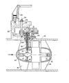
- the figure schematically represents a view in partial section, of the apparatus by a plane parallel to the axis and passing through the common axis of the adjustment flap and of the movement output shaft of the turbine.
- a turbine 11 mounted coaxially in rotation on two half-shafts 12,13 between two hollow fairings 14,15 connected to the element 10 by ribs 16 of substantially radial orientation.
- the fluid flows in the element 10 in the direction of the arrow.
- a flap 17 of angular orientation adjustable around an axis approximately perpendicular to the axis of the pipe is provided for calibrating the device.
- the flap 17 is integral with a tubular axis 18 which pivots at its lower end in an opening in the upstream fairing 14 and which has a shoulder 18A resting on a recess corresponding to the pipe element 10.
- the upper end of the axis 18 located in a chamber 19, formed between the pipe element 10 and a closure part 20, carries a toothed sector 21 which meshes with a pinion 22
- the pinion 22 is mounted on a shaft 23 parallel to the axis 18 which has at its upper end a slot 24 allowing using a screwdriver to orient the flap 17.
- a nut 25 ensures the blocking of the shaft 23 in a fixed position and thus maintains the flap 17 along the angular orientation determined during the calibration operation of the device.
- An auxiliary part 26 fixed to the pipe element 10 maintains the axis 18 in its housing against the pressure of the fluid and also clamps an annular seal 27 acting as a vibration damper.
- the device is closed at its upper part by a cover 29 (partially shown) sealed after calibration of the device and preventing any access to the shaft 23.
- the rotational movement of the turbine 11 is transmitted to an output shaft 30 by means of a tangent screw 31-pinion 32 pair disposed inside the upstream fairing 14.
- the output shaft 30 passes, according to the invention , through the tubular axis 18 of the flap 17 and transmits its movement to a set of reducing gears partially shown 33 mounted in the chamber 19 and connected to the totalizer of the device possibly via a magnetic transmission through a tight wall.
- the shaft 30 pivots at its base in a clamp 34 mounted inside the fairing 14 and at its upper part in a bearing 28 provided in the tubular axis 18.
Landscapes
- Physics & Mathematics (AREA)
- Fluid Mechanics (AREA)
- General Physics & Mathematics (AREA)
- Measuring Volume Flow (AREA)
Abstract
Description
- La présente invention est relative aux appareils de mesure de débit de fluides à turbine axiale, du genre compteurs de Woltmann, dans lesquels la quantité de fluide s'écoulant dans une conduite est mesurée au moyen d'une turbine montée axialement dans cette conduite et fournissant un nombre de tours représentatif du débit à mesurer.
- Dans les appareils de ce genre à sortie mécanique, on prévoit généralement pour détecter le nombre de tours de la turbine, une vis sans fin montée en aval sur l'arbre de la turbine qui engrène avec un pj-gnon monté sur un autre arbre perpendiculaire à l'axe de la conduite et qui transmet à l'extérieur de la conduite l'information cherchée à un mécanisme de comptage.
- De plus, ces appareils comportent aussi un volet de réglage qui est disposé en amont de la turbine pivotant sur un axe perpendiculaire à celui de la conduite et dont l'orientation angulaire est réglée en usine une fois pour toutes au cours de l'opération d'étalonnage de l'appareil.
- Les deux éléments précités, l'arbre de sortie de mouvement d'une part, l'axe du volet de réglage d'autre part, constituent des obstacles à l'écoulement du fluide et ont par suite l'inconvénient de créer respectivement une perte de charge dans l'appareil de mesure. L'invention a pour objet un appareil de mesure de débit du type indiqué dans lequel la perte de charge due aux éléments ci-dessus est en grande partie diminuée grâce à une modification de structure de l'appareil.
- L'appareil de mesure, suivant l'invention, comporte dans un élément de conduite tubulaire :
- - une turbine montée à rotation sur un arbre coaxial audit élément,
- - un arbre de sortie de mouvement couplé audit arbre de la turbine pour détecter le nombre de tours effectués par la turbine.
- - et un volet de réglage orientable autour d'un axe en amont de la turbine pour l'étalonnage de l'appareil,
- De préférence, l'arbre de sortie de mouvement passe à l'intérieur de l'axe du volet de réglage.
- Cette structure a l'avantage de ne plus nécessiter sur le trajet du fluide qu'un obstacle unique, de sorte que la perte de charge se trouve diminuée vis-à-vis de celle existant dans les appareils de la technique antérieure. Un autre avantage consiste en une réduction du nombre de pièces du compteur.
- L'invention est applicable aux appareils de mesure de débits de fluides en général, et notamment aux compteurs d'eau de gros calibres.
- L'invention sera mieux comprise en se référant à la description suivante et au dessin annexé donné à titre d'exemple non limitatif d'un mode de réalisation d'un appareil conforme à l'invention.
- Sur ce dessin, la figure représente schématiquement une vue en coupe partielle, de l'appareil par un plan parallèle à l'axe et passant par l'axe commun du volet de réglage et de l'arbre de sortie de mouvement de la turbine.
- Dans un élément de conduite tubulaire 10, on voit une turbine 11 montée coaxialement à rotation sur deux demi-arbres 12,13 entre deux carénages creux 14,15 reliés à l'élément 10 par des nervures 16 d'orientation sensiblement radiale. Le fluide s'écoule dans l'élément 10 suivant le sens de la flèche.
- En amont de la turbine 11, un volet 17 d'orientation angulaire réglable autour d'un axe approximativement perpendiculaire à l'axe de la conduite, est prévu pour l'étalonnage de l'appareil. Le volet 17 est solidaire d'un axe tubulaire 18 qui pivote à son extrémité inférieure dans une ouverture du carénage amont 14 et qui présente un épaulement 18A reposant sur un évidement correspondant de l'élément de conduite 10. L'extrémité supérieure de l'axe 18 située dans une chambre 19, formée entre l'élément de conduite 10 et une pièce de fermeture 20, porte un secteur denté 21 qui engrène avec un pignon 22. Le pignon 22 est monté sur un arbre 23 parallèle à l'axe 18 qui présente à son extrémité supérieure une fente 24 permettant à l'aide d'un tournevis d'orienter le volet 17. Un écrou 25 assure le blocage de l'arbre 23 dans une position fixe et maintient ainsi le volet 17 suivant l'orientation angulaire déterminée au cours de l'opération d'étalonnage de l'appareil. Une pièce auxiliaire 26 fixée sur l'élément de conduite 10 maintient l'axe 18 dans son logement contre la pression du fluide et serre aussi un joint annulaire 27 faisant office d'amortisseur de vibrations. 'L'apparsil est fermé à sa partie supérieure par un couvercle 29 (partiellement représenté) plombé après étalonnage de l'appareil et interdisant tout accès à l'arbre 23.
- Le mouvement de rotation de la turbine 11 est transmis à un arbre de sortie 30 au moyen d'un couple vis tangente 31-pignon 32 disposé à l'intérieur du carénage amont 14. L'arbre de sortie 30 passe, suivant l'invention, à travers l'axe tubulaire 18 du volet 17 et transmet son mouvement à un ensemble d'engrenages réducteurs partiellement représenté 33 monté dans la chambre 19 et relié au totalisateur de l'appareil éventuellement par l'intermédiaire d'une transmission magnétique à travers une paroi étanche. L'arbre 30 pivote à sa base dans une crapaudine 34 montée à l'intérieur du carénage 14 et à sa partie supérieure dans un palier 28 prévu dans l'axe tubulaire 18.
et il est caractérisé en ce que ledit arbre de sortie de mouvement et ledit axe du volet de réglage sont coaxiaux.
Claims (3)
caractérisé en ce que ledit arbre de sortie de mouvement (30) et ledit axe (18) du volet de réglage (17) sont coaxiaux.
Applications Claiming Priority (2)
| Application Number | Priority Date | Filing Date | Title |
|---|---|---|---|
| FR8119892 | 1981-10-23 | ||
| FR8119892A FR2515338A1 (fr) | 1981-10-23 | 1981-10-23 | Perfectionnements aux compteurs de woltmann |
Publications (2)
| Publication Number | Publication Date |
|---|---|
| EP0078210A1 true EP0078210A1 (fr) | 1983-05-04 |
| EP0078210B1 EP0078210B1 (fr) | 1985-09-11 |
Family
ID=9263307
Family Applications (1)
| Application Number | Title | Priority Date | Filing Date |
|---|---|---|---|
| EP19820401943 Expired EP0078210B1 (fr) | 1981-10-23 | 1982-10-22 | Perfectionnement aux compteurs Woltmann |
Country Status (7)
| Country | Link |
|---|---|
| EP (1) | EP0078210B1 (fr) |
| BR (1) | BR8206176A (fr) |
| DE (1) | DE3266223D1 (fr) |
| ES (1) | ES516746A0 (fr) |
| FI (1) | FI70324C (fr) |
| FR (1) | FR2515338A1 (fr) |
| PT (1) | PT75715B (fr) |
Cited By (1)
| Publication number | Priority date | Publication date | Assignee | Title |
|---|---|---|---|---|
| WO1991004462A3 (fr) * | 1989-09-25 | 1991-05-16 | Bopp & Reuther Ag | Fluidimetre |
Citations (2)
| Publication number | Priority date | Publication date | Assignee | Title |
|---|---|---|---|---|
| DE960862C (de) * | 1952-12-18 | 1957-03-28 | Bopp & Reuther Gmbh | Fluegelradlagerung fuer Woltmannzaehler |
| DE1948622A1 (de) * | 1969-09-26 | 1971-04-01 | Bopp & Reuther Gmbh | Woltmannfluessigkeitszaehler |
-
1981
- 1981-10-23 FR FR8119892A patent/FR2515338A1/fr active Granted
-
1982
- 1982-10-20 FI FI823589A patent/FI70324C/fi not_active IP Right Cessation
- 1982-10-21 PT PT7571582A patent/PT75715B/fr unknown
- 1982-10-22 ES ES516746A patent/ES516746A0/es active Granted
- 1982-10-22 DE DE8282401943T patent/DE3266223D1/de not_active Expired
- 1982-10-22 BR BR8206176A patent/BR8206176A/pt not_active IP Right Cessation
- 1982-10-22 EP EP19820401943 patent/EP0078210B1/fr not_active Expired
Patent Citations (2)
| Publication number | Priority date | Publication date | Assignee | Title |
|---|---|---|---|---|
| DE960862C (de) * | 1952-12-18 | 1957-03-28 | Bopp & Reuther Gmbh | Fluegelradlagerung fuer Woltmannzaehler |
| DE1948622A1 (de) * | 1969-09-26 | 1971-04-01 | Bopp & Reuther Gmbh | Woltmannfluessigkeitszaehler |
Cited By (1)
| Publication number | Priority date | Publication date | Assignee | Title |
|---|---|---|---|---|
| WO1991004462A3 (fr) * | 1989-09-25 | 1991-05-16 | Bopp & Reuther Ag | Fluidimetre |
Also Published As
| Publication number | Publication date |
|---|---|
| FR2515338A1 (fr) | 1983-04-29 |
| FI823589A0 (fi) | 1982-10-20 |
| FI70324C (fi) | 1986-09-15 |
| PT75715A (fr) | 1982-11-01 |
| ES8308062A1 (es) | 1983-07-01 |
| BR8206176A (pt) | 1983-09-20 |
| PT75715B (fr) | 1986-01-10 |
| EP0078210B1 (fr) | 1985-09-11 |
| FI823589L (fi) | 1983-04-24 |
| FI70324B (fi) | 1986-02-28 |
| ES516746A0 (es) | 1983-07-01 |
| DE3266223D1 (en) | 1985-10-17 |
| FR2515338B1 (fr) | 1983-12-30 |
Similar Documents
| Publication | Publication Date | Title |
|---|---|---|
| FR2480936A1 (fr) | Appareil de reglage de debit, notamment pour des canalisations de liquides | |
| CA1232683A (fr) | Procede et dispositif de mesure des debits des phases liquide et gazeuse d'un fluide diphasique en ecoulement | |
| FR2827360A1 (fr) | Vanne de commande pour un circuit de circulation de fluide, en particulier pour un circuit de refroidissement d'un moteur | |
| FR2504259A1 (fr) | Debitmetre a fluide | |
| FR2542825A1 (fr) | Appareil tranquilliseur pour regulariser le profil des vitesses d'un fluide en ecoulement | |
| FR2737563A1 (fr) | Compteur de liquide a jet unique a couple moteur ameliore | |
| EP0078210B1 (fr) | Perfectionnement aux compteurs Woltmann | |
| FR2512513A1 (fr) | Vanne de commande d'un fluide | |
| FR2487972A1 (fr) | Debitmetre pour liquide | |
| FR2522780A1 (fr) | Dispositif de determination de grandeurs mesurees dans des tuyauteries | |
| CH435781A (fr) | Procédé pour mesurer le débit massique d'un fluide et débitmètre pour la mise en oeuvre de ce procédé | |
| FR2461929A1 (fr) | Debitmetre du type rotametre | |
| EP0191687B1 (fr) | Dispositif de variation de section du col d'un distributeur de turbine | |
| JP3335480B2 (ja) | 管内設置型流量計 | |
| FR2530335A1 (fr) | Appareil regulateur d'ecoulement | |
| EP0076189A1 (fr) | Perfectionnements aux appareils de mesure de débit à turbine axiale | |
| GB2036333A (en) | Fluid flow meter | |
| FR2463349A1 (fr) | Dispositif de montage pour actionneur de telecommande | |
| CN115615509A (zh) | 一种一体化节流式流量计 | |
| FR2700388A1 (fr) | Palier de Turbine pour Compteur de liquide. | |
| FR2625543A1 (fr) | Nouveau clapet pour canalisations | |
| CH385504A (fr) | Compteur à moulinet | |
| FR2513724A1 (fr) | Vannes en deux parties a montage rapide | |
| JPS6146418Y2 (fr) | ||
| FR2958760A1 (fr) | Agencement debitmetre de gaz a detente |
Legal Events
| Date | Code | Title | Description |
|---|---|---|---|
| PUAI | Public reference made under article 153(3) epc to a published international application that has entered the european phase |
Free format text: ORIGINAL CODE: 0009012 |
|
| AK | Designated contracting states |
Designated state(s): BE CH DE GB IT LI NL SE |
|
| 17P | Request for examination filed |
Effective date: 19830930 |
|
| ITF | It: translation for a ep patent filed | ||
| GRAA | (expected) grant |
Free format text: ORIGINAL CODE: 0009210 |
|
| AK | Designated contracting states |
Designated state(s): BE CH DE GB IT LI NL SE |
|
| REF | Corresponds to: |
Ref document number: 3266223 Country of ref document: DE Date of ref document: 19851017 |
|
| PLBE | No opposition filed within time limit |
Free format text: ORIGINAL CODE: 0009261 |
|
| STAA | Information on the status of an ep patent application or granted ep patent |
Free format text: STATUS: NO OPPOSITION FILED WITHIN TIME LIMIT |
|
| 26N | No opposition filed | ||
| PGFP | Annual fee paid to national office [announced via postgrant information from national office to epo] |
Ref country code: SE Payment date: 19911004 Year of fee payment: 10 |
|
| ITTA | It: last paid annual fee | ||
| PG25 | Lapsed in a contracting state [announced via postgrant information from national office to epo] |
Ref country code: SE Effective date: 19921023 |
|
| EUG | Se: european patent has lapsed |
Ref document number: 82401943.4 Effective date: 19930510 |
|
| PGFP | Annual fee paid to national office [announced via postgrant information from national office to epo] |
Ref country code: BE Payment date: 19980911 Year of fee payment: 17 |
|
| PGFP | Annual fee paid to national office [announced via postgrant information from national office to epo] |
Ref country code: NL Payment date: 19981031 Year of fee payment: 17 |
|
| PG25 | Lapsed in a contracting state [announced via postgrant information from national office to epo] |
Ref country code: BE Free format text: LAPSE BECAUSE OF NON-PAYMENT OF DUE FEES Effective date: 19991031 |
|
| BERE | Be: lapsed |
Owner name: FLONIC S.A. Effective date: 19991031 |
|
| PG25 | Lapsed in a contracting state [announced via postgrant information from national office to epo] |
Ref country code: NL Free format text: LAPSE BECAUSE OF NON-PAYMENT OF DUE FEES Effective date: 20000501 |
|
| NLV4 | Nl: lapsed or anulled due to non-payment of the annual fee |
Effective date: 20000501 |
|
| PGFP | Annual fee paid to national office [announced via postgrant information from national office to epo] |
Ref country code: GB Payment date: 20011024 Year of fee payment: 20 |
|
| REG | Reference to a national code |
Ref country code: GB Ref legal event code: IF02 |
|
| PGFP | Annual fee paid to national office [announced via postgrant information from national office to epo] |
Ref country code: DE Payment date: 20020327 Year of fee payment: 20 |
|
| PGFP | Annual fee paid to national office [announced via postgrant information from national office to epo] |
Ref country code: CH Payment date: 20020328 Year of fee payment: 20 |
|
| PG25 | Lapsed in a contracting state [announced via postgrant information from national office to epo] |
Ref country code: LI Free format text: LAPSE BECAUSE OF EXPIRATION OF PROTECTION Effective date: 20021021 Ref country code: GB Free format text: LAPSE BECAUSE OF EXPIRATION OF PROTECTION Effective date: 20021021 Ref country code: CH Free format text: LAPSE BECAUSE OF EXPIRATION OF PROTECTION Effective date: 20021021 |
|
| REG | Reference to a national code |
Ref country code: GB Ref legal event code: PE20 Effective date: 20021021 |
|
| REG | Reference to a national code |
Ref country code: CH Ref legal event code: PL |