EP0078327A1 - Steuerverfahren für die spindeldrehgeschwindigkeit - Google Patents
Steuerverfahren für die spindeldrehgeschwindigkeit Download PDFInfo
- Publication number
- EP0078327A1 EP0078327A1 EP82901433A EP82901433A EP0078327A1 EP 0078327 A1 EP0078327 A1 EP 0078327A1 EP 82901433 A EP82901433 A EP 82901433A EP 82901433 A EP82901433 A EP 82901433A EP 0078327 A1 EP0078327 A1 EP 0078327A1
- Authority
- EP
- European Patent Office
- Prior art keywords
- velocity
- percentage
- spindle
- change
- rotational
- Prior art date
- Legal status (The legal status is an assumption and is not a legal conclusion. Google has not performed a legal analysis and makes no representation as to the accuracy of the status listed.)
- Granted
Links
Images

Classifications
-
- G—PHYSICS
- G05—CONTROLLING; REGULATING
- G05B—CONTROL OR REGULATING SYSTEMS IN GENERAL; FUNCTIONAL ELEMENTS OF SUCH SYSTEMS; MONITORING OR TESTING ARRANGEMENTS FOR SUCH SYSTEMS OR ELEMENTS
- G05B19/00—Program-control systems
- G05B19/02—Program-control systems electric
- G05B19/18—Numerical control [NC], i.e. automatically operating machines, in particular machine tools, e.g. in a manufacturing environment, so as to execute positioning, movement or co-ordinated operations by means of program data in numerical form
- G05B19/406—Numerical control [NC], i.e. automatically operating machines, in particular machine tools, e.g. in a manufacturing environment, so as to execute positioning, movement or co-ordinated operations by means of program data in numerical form characterised by monitoring or safety
- G05B19/4062—Monitoring servoloop, e.g. overload of servomotor, loss of feedback or reference
-
- B—PERFORMING OPERATIONS; TRANSPORTING
- B23—MACHINE TOOLS; METAL-WORKING NOT OTHERWISE PROVIDED FOR
- B23Q—DETAILS, COMPONENTS, OR ACCESSORIES FOR MACHINE TOOLS, e.g. ARRANGEMENTS FOR COPYING OR CONTROLLING; MACHINE TOOLS IN GENERAL CHARACTERISED BY THE CONSTRUCTION OF PARTICULAR DETAILS OR COMPONENTS; COMBINATIONS OR ASSOCIATIONS OF METAL-WORKING MACHINES, NOT DIRECTED TO A PARTICULAR RESULT
- B23Q15/00—Automatic control or regulation of feed movement, cutting velocity or position of tool or work
- B23Q15/007—Automatic control or regulation of feed movement, cutting velocity or position of tool or work while the tool acts upon the workpiece
- B23Q15/12—Adaptive control, i.e. adjusting itself to have a performance which is optimum according to a preassigned criterion
-
- G—PHYSICS
- G05—CONTROLLING; REGULATING
- G05B—CONTROL OR REGULATING SYSTEMS IN GENERAL; FUNCTIONAL ELEMENTS OF SUCH SYSTEMS; MONITORING OR TESTING ARRANGEMENTS FOR SUCH SYSTEMS OR ELEMENTS
- G05B2219/00—Program-control systems
- G05B2219/30—Nc systems
- G05B2219/37—Measurements
- G05B2219/37296—Electronic graduation, scale expansion, interpolation
-
- G—PHYSICS
- G05—CONTROLLING; REGULATING
- G05B—CONTROL OR REGULATING SYSTEMS IN GENERAL; FUNCTIONAL ELEMENTS OF SUCH SYSTEMS; MONITORING OR TESTING ARRANGEMENTS FOR SUCH SYSTEMS OR ELEMENTS
- G05B2219/00—Program-control systems
- G05B2219/30—Nc systems
- G05B2219/37—Measurements
- G05B2219/37536—Rate of change, derivative
-
- G—PHYSICS
- G05—CONTROLLING; REGULATING
- G05B—CONTROL OR REGULATING SYSTEMS IN GENERAL; FUNCTIONAL ELEMENTS OF SUCH SYSTEMS; MONITORING OR TESTING ARRANGEMENTS FOR SUCH SYSTEMS OR ELEMENTS
- G05B2219/00—Program-control systems
- G05B2219/30—Nc systems
- G05B2219/42—Servomotor, servo controller kind till VSS
- G05B2219/42309—Excess in speed
Definitions
- This invention relates to a method of checking the rotational frequency of a spindle in a numerically controlled machine tool.
- a spindle is rotated at a speed in accordance with a rotational frequency command from a numerical control device (referred to as an NC), whereby a workpiece or tool is caused to rotate.
- a numerical control device referred to as an NC
- a spindle is rotated on the basis of an S-function instruction (a spindle rotational frequency instruction issued in the form of the letter of the alphabet S followed by a two-digit numerical value) from an NC, whereby a workpiece loaded on the spindle via a chuck is caused to rotate.
- S-function instruction a spindle rotational frequency instruction issued in the form of the letter of the alphabet S followed by a two-digit numerical value
- a cutter is transported in the direction of the central axis of the workpiece (the Z-direction) and in a direction orthogonal thereto (the X-direction) to subject the workpiece to a predetermined turning or thread cutting operation.
- thread cutting work threads cannot be cut at a precise pitch unless the spindle is rotated at the commanded velocity.
- Even in an ordinary turning operation moreover, tool life is shortened unless the spindle is rotated at a commanded velocity, namely at the commanded rotational frequency.
- a screw tap mounted on a spindle is rotated in accordance with a commanded rotational velocity while the screw tap is transported in synchronism with the rotational velocity to cut threads in a workpiece. Accurate thread cutting cannot be carried out unless the screw tap is rotated at the commanded-velocity.
- an object of the present invention is to provide a novel method of checking the rotational frequency of a spindle wherein, when the spindle rotational frequency is checked and found to exceed the allowable percentage of change, or when the actual rotational velocity does not attain a predetermined velocity even after the passage of a prescribed length of time following a change in commanded velocity, these phenomena are regarded as being abnormalities in response to which an alarm signal is produced.
- the present invention provides a novel method of checking the rotational frequency of a spindle wherein an alarm is produced when the spindle rotational frequency is checked and found to exceed an allowable percentage of change, or when the actual rotational velocity does not attain a predetermined velocity even after the passage of a prescribed length of time following a change in commanded velocity.
- this checking method machining will not continue on the basis of an abnormal spindle rotational frequency, so that a higher accuracy can be obtained for machining performed by a variety of machine tools.
- Fig. l(a) and Fig. l(b) are explantory views for explaining a method of checking the rotational frequency of a spindle
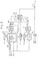
- Fig. 2 is a block diagram.
- Fig. l(a), Fig. 1(b) and Fig. 2 are explanatory views for explaining a method of checking the rotational frequency of a spindle according to the present invention.
- AVC represents an actual velocity curve
- Nc 1 an initial commanded rotational velocity
- Nc 2 a commanded rotational velocity issued at a time t 1
- TRV 1 a zone of maximum allowable velocity change decided based on an already given maximum allowable percentage of velocity change g
- TRV 2 a commanded velocity zone wherein actual rotational velocity is regarded to have attained a commanded velocity.
- This commanded velocity zone is decided based on a percentage of velocity change r that determines whether a commanded rotational frequency has been reached.
- the character p represents an already given maximum allowable time period.
- the rotational frequency of the spindle begins to be checked using the zone TRV 1 of maximum allowable speed change.
- the commanded rotational velocity Nc 1 is changed to Nc 2 at time t l .
- the actual rotational velocity attains the commanded rotational velocity Nc 2 after a predetermined period of time corresponding to the delay of the servo system, after which rotation continues at the commanded rotational velocity Nc 2 .
- Fig. l(b) let us assume that the commanded rotational velocity is changed from Nc 1 to Nc 2 at time t l . If the servo system is operating normally, the actual rotational velocity will reach the commanded rotational velocity Nc 2 after a predetermined period of time. If the servo system develops an abnormality, however, the actual rotational velocity will not reach the commanded velocity zone TRV 2 even after the passage of time p. In such case, according to the invention, the rotational frequency of the spindle begins to be checked on the basis of the zone TVR 1 of maximum allowable velocity change, immediately after the passage of time p.
- Fig. 2 is a block diagram illustrating an embodiment of the present invention.
- numeral 101 denotes a register for storing a maximum allowable percentage of velocity change r
- 102 a register for storing a percentage of velocity change g which determines whether a commanded rotational frequency has been reached
- 103 a register for storing maximum allowable time p.
- the G-function instruction G26 indicative of the check mode is a modal, and that the rotational frequency of the spindle is being checked at all times barring the arrival of a command representing a G-function instruction: that is indicative of a CHECK OFF mode.
- p, q and r can be stored beforehand, along with various parameters, in a bubble memory or the like so as to preserve"even if the NC power supply goes down. If p, q and r are thus stored previously in a bubble memory in the form of parameters, then it will suffice to issue merely the following command, namely: as the NC command for the check mode.
- Numeral 104 denotes a flip-flop (referred to as an FF) for memorizing the check mode, which FF is set by G26 and reset by G25.
- Numeral 105 denotes a register .
- the arithmetic unit 106 receives, as input signals, the commanded rotational frequency N c and the actual rotational velocity N , and performs the following a arithmetic operation to compute the percentage of velocity change ⁇ :
- a pulse coder such as a position coder is mounted on the spindle for generating a pulse each time the spindle rotates by a predetermined amount.
- the actual rotational velocity N a is found by counting the pulses generated over a predetermined time period followed by reading the counted value. It should also be noted that the actual rotational velocity is fed back to the NC for controlling spindle rotation.
- Numeral 108 denotes a comparator for comparing, in terms of magnitude, the percentage of velocity changed and the preset percentage of velocity change g.
- Numeral 110 denotes a comparator for comparing, in terms of magnitude, the percentage of velocity change ⁇ and the maximum allowable percentage of velocity change r after the actual rotational velocity N a has reached commanded velocity zone TRV 2 .
- Numeral 111 designates a comparator for comparing, in terms of magnitude, elapsed time T p and maximum allowable time P [Fig. 1(b)] after the new velocity command signal NVC goes to logical "I".
- T p > P holds, the comparator 111 produces a time-over signal TPS of logic level "1".
- Numerals 112, 113 denote AND gates, and 114 an OR gate.
- the new rotational velocity Nc 2 is set in the register 105 in place of the old rotational velocity Ncl, and the new speed command signal NVC goes to logical "1" to reset the flip-flop 109 and to start the timer 107.
- the percentage of change arithmetic unit 106 is constantly executing the operation of Eq. (1), the result of which operation, namely a,-is delivered to the comparator 108. The latter compares the magnitude of this percentage of velocity change ⁇ with the magnitude of the given percentage of velocity change g.
- the comparator 110 thenceforth compares, in magnitude, the percentage of velocity change ⁇ , which is the output of the arithmetic unit 106, and the maximum allowable percentage of velocity change r preset in the register 101. Specifically, the comparator 110 discriminates whether the actual rotational velocity N a falls outside the zone TRV 1 of maximum allowable velocity change [Fig. l(a)] because of the servo system or some other cause.
- the foregoing is for a case where an abnormality develops in, e.g., the servo system after the actual rotational velocity Na reaches the commanded velocity zone TRV 2 .
- an abnormality develops in the servo system before the commanded velocity zone TRV 2 is reached, with the actual rotational velocity N a not attaining the zone TRV 2 even after the passage of a predetermined time period.
- the comparator 111 produces the time-over signal TPS, whereby a signal is fed into the comparator 110 through the AND gate 112 and OR gate 114, before the flip-flop 109 is set.
- the comparator 110 compares the percentage of velocity change ⁇ and the maximum allowable percentage of velocity change r. Since ⁇ > r at this time, the AND gate 113 delivers the alarm signal AL immediately.
- the alarm signal is delivered to the machine tool side immediately, and that the NC comes to an alarm stop.
- an alarm signal is issued, indicative of an abnormality in a servo system or elsewhere, when a fluctuation in the rotational frequency of a spindle falls outside a maximum allowable velocity range decided by a maximum allowable percentage of velocity change, or when the rotational frequency of the spindle does not attain the vicinity of a commanded velocity even after the passage of a predetermined period of time following a change in commanded velocity.
- an abnormality in the spindle servo system or spindle mechanism can be checked without machining being continued at the abnormal rotational frequency.
- problems caused by seizure of a guide bush in the machining of bar stock can be checked rapidly.
- two quantities are set, namely maximum allowable percentage of change for judging malfunctions, and percentage of change for judging whether the commanded speed has been reached.
- the timing at which checking starts and stops is decided automatically by the NC.
- the rotational frequency of the spindle can therefore be checked not only when a rotational frequency is commanded by the program, but also when'the rotational frequency is changed automatically internally of the NC to perform a turning machining operation, as when machining is carried out in a mode for constant peripheral speed control.
Landscapes
- Engineering & Computer Science (AREA)
- Human Computer Interaction (AREA)
- Manufacturing & Machinery (AREA)
- Physics & Mathematics (AREA)
- General Physics & Mathematics (AREA)
- Automation & Control Theory (AREA)
- Mechanical Engineering (AREA)
- Numerical Control (AREA)
Applications Claiming Priority (2)
| Application Number | Priority Date | Filing Date | Title |
|---|---|---|---|
| JP72832/81 | 1981-05-14 | ||
| JP56072832A JPS57189752A (en) | 1981-05-14 | 1981-05-14 | Main shaft rotation speed check system |
Publications (3)
| Publication Number | Publication Date |
|---|---|
| EP0078327A1 true EP0078327A1 (de) | 1983-05-11 |
| EP0078327A4 EP0078327A4 (de) | 1986-02-10 |
| EP0078327B1 EP0078327B1 (de) | 1989-12-20 |
Family
ID=13500776
Family Applications (1)
| Application Number | Title | Priority Date | Filing Date |
|---|---|---|---|
| EP82901433A Expired EP0078327B1 (de) | 1981-05-14 | 1982-05-14 | Steuerverfahren für die spindeldrehgeschwindigkeit |
Country Status (6)
| Country | Link |
|---|---|
| US (1) | US4591990A (de) |
| EP (1) | EP0078327B1 (de) |
| JP (1) | JPS57189752A (de) |
| KR (1) | KR890000578B1 (de) |
| DE (1) | DE3280065D1 (de) |
| WO (1) | WO1982004005A1 (de) |
Cited By (2)
| Publication number | Priority date | Publication date | Assignee | Title |
|---|---|---|---|---|
| EP0365681A4 (en) * | 1988-03-10 | 1990-12-19 | Fanuc Ltd | Method of detecting collision of moving portions driven by servo motor |
| EP0414643A3 (en) * | 1989-08-16 | 1992-08-12 | Megamation Incorporated | Method and apparatus for monitoring and controlling linear motor robot apparatus and the like |
Families Citing this family (4)
| Publication number | Priority date | Publication date | Assignee | Title |
|---|---|---|---|---|
| US4718078A (en) * | 1985-08-19 | 1988-01-05 | Siemens Aktiengesellschaft | System for controlling motion of a robot |
| JPS62144147U (de) * | 1986-03-05 | 1987-09-11 | ||
| JPH02130739U (de) * | 1989-03-31 | 1990-10-29 | ||
| JP2022162634A (ja) * | 2021-04-13 | 2022-10-25 | 株式会社ディスコ | 加工装置 |
Family Cites Families (16)
| Publication number | Priority date | Publication date | Assignee | Title |
|---|---|---|---|---|
| JPS4926230B1 (de) * | 1968-02-09 | 1974-07-06 | ||
| JPS4845174U (de) * | 1971-09-27 | 1973-06-13 | ||
| US4267458A (en) * | 1972-04-26 | 1981-05-12 | Westinghouse Electric Corp. | System and method for starting, synchronizing and operating a steam turbine with digital computer control |
| GB1472055A (en) * | 1973-04-06 | 1977-04-27 | Srm Hydromekanik Ab | Control system for a transmission |
| DE2337199C3 (de) * | 1973-07-21 | 1980-08-14 | Kiepe Elektrik Gmbh, 4000 Duesseldorf | Schaltungsanordnung zum Überwachen von Drehzahlen |
| US4076999A (en) * | 1976-02-19 | 1978-02-28 | General Electric Company | Circuit for limiting the spindle speed of a machine |
| FR2362400A1 (fr) * | 1976-02-25 | 1978-03-17 | Thomson Csf | Dispositif de mesure de la vitesse de rotation d'un arbre de son controle et du controle de ses variations |
| FR2366152A1 (fr) * | 1976-10-04 | 1978-04-28 | Dba | Dispositif electronique de commande d'antipatinage pour systeme de freinage de vehicule automobile |
| US4078750A (en) * | 1977-03-08 | 1978-03-14 | United Technologies Corporation | Speed-variable limits in fail-safe actuators |
| JPS5541249Y2 (de) * | 1977-05-30 | 1980-09-26 | ||
| JPS5541249A (en) * | 1978-09-18 | 1980-03-24 | Dainichi Concrete Kogyo Kk | Cement waste liquor concentration molding method |
| JPS5575445U (de) * | 1978-11-16 | 1980-05-24 | ||
| JPS5654523A (en) * | 1979-10-09 | 1981-05-14 | Fanuc Ltd | Controller for stopping main axle at fixed position |
| JPS5653944A (en) * | 1979-10-09 | 1981-05-13 | Nissan Motor Co Ltd | Antiskid controller |
| JPS5674708A (en) * | 1979-11-26 | 1981-06-20 | Toyoda Mach Works Ltd | Numerical control device |
| US4350941A (en) * | 1980-09-19 | 1982-09-21 | Ford Motor Company | Control for automatic machine tool drive |
-
1981
- 1981-05-14 JP JP56072832A patent/JPS57189752A/ja active Granted
-
1982
- 1982-05-13 KR KR8202083A patent/KR890000578B1/ko not_active Expired
- 1982-05-14 US US06/761,671 patent/US4591990A/en not_active Expired - Lifetime
- 1982-05-14 DE DE8282901433T patent/DE3280065D1/de not_active Expired - Lifetime
- 1982-05-14 EP EP82901433A patent/EP0078327B1/de not_active Expired
- 1982-05-14 WO PCT/JP1982/000169 patent/WO1982004005A1/ja not_active Ceased
Cited By (2)
| Publication number | Priority date | Publication date | Assignee | Title |
|---|---|---|---|---|
| EP0365681A4 (en) * | 1988-03-10 | 1990-12-19 | Fanuc Ltd | Method of detecting collision of moving portions driven by servo motor |
| EP0414643A3 (en) * | 1989-08-16 | 1992-08-12 | Megamation Incorporated | Method and apparatus for monitoring and controlling linear motor robot apparatus and the like |
Also Published As
| Publication number | Publication date |
|---|---|
| KR830009894A (ko) | 1983-12-24 |
| JPS57189752A (en) | 1982-11-22 |
| JPS6315099B2 (de) | 1988-04-02 |
| KR890000578B1 (ko) | 1989-03-21 |
| EP0078327A4 (de) | 1986-02-10 |
| US4591990A (en) | 1986-05-27 |
| EP0078327B1 (de) | 1989-12-20 |
| WO1982004005A1 (fr) | 1982-11-25 |
| DE3280065D1 (de) | 1990-01-25 |
Similar Documents
| Publication | Publication Date | Title |
|---|---|---|
| US4748554A (en) | Machine monitoring system using motion detection for synchronization | |
| EP0970409B1 (de) | Numerisch gesteuerte maschine mit interaktiver regelung der winkeltoleranz | |
| EP0086846A1 (de) | Numerische steuereinheit | |
| US4604705A (en) | Numerical control machining method and system therefor | |
| US4481568A (en) | Numerical control method and apparatus | |
| EP0171437A1 (de) | Gewindebohrmethode | |
| CN105988417B (zh) | 进行螺纹孔检查的数值控制装置 | |
| DE102015115663B4 (de) | Werkzeugmaschinensteuerung für die einrollbearbeitung | |
| KR930010589B1 (ko) | 절삭공구의 정지 제어장치 | |
| EP0078327A1 (de) | Steuerverfahren für die spindeldrehgeschwindigkeit | |
| EP0439617A1 (de) | Regelungssystem für die beschleunigung/verzögerung einer steuerung mit numerischen daten | |
| JPH07136906A (ja) | 数値制御装置 | |
| US6628097B2 (en) | Machine tool and control method therefor | |
| EP0593758B1 (de) | Werkstückwechseleinrichtung | |
| US5313861A (en) | Workpiece exchanging system | |
| US4787834A (en) | Metering apparatus of injection molding machine | |
| JPH11202926A (ja) | 数値制御における送り速度制御方法および装置 | |
| EP0067232A1 (de) | Digital gesteuerte drahtschneidevorrichtung | |
| EP0646852B1 (de) | Regelungssystem für die beschleunigung/verzögerung einer numerischen steuerung | |
| US5112169A (en) | Thread cutting method and apparatus | |
| JPH0630011B2 (ja) | 数値制御加工再開制御方式 | |
| JPH0258053B2 (de) | ||
| JPH0751992A (ja) | 穴開け加工方式 | |
| EP0266427A1 (de) | Hydraulisch angetriebene revolverindexiervorrichtung | |
| US5081407A (en) | Numerical control apparatus |
Legal Events
| Date | Code | Title | Description |
|---|---|---|---|
| PUAI | Public reference made under article 153(3) epc to a published international application that has entered the european phase |
Free format text: ORIGINAL CODE: 0009012 |
|
| 17P | Request for examination filed |
Effective date: 19830107 |
|
| AK | Designated contracting states |
Designated state(s): DE FR GB |
|
| A4 | Supplementary search report drawn up and despatched |
Effective date: 19860210 |
|
| 17Q | First examination report despatched |
Effective date: 19880729 |
|
| GRAA | (expected) grant |
Free format text: ORIGINAL CODE: 0009210 |
|
| AK | Designated contracting states |
Kind code of ref document: B1 Designated state(s): DE FR GB |
|
| REF | Corresponds to: |
Ref document number: 3280065 Country of ref document: DE Date of ref document: 19900125 |
|
| ET | Fr: translation filed | ||
| PLBE | No opposition filed within time limit |
Free format text: ORIGINAL CODE: 0009261 |
|
| STAA | Information on the status of an ep patent application or granted ep patent |
Free format text: STATUS: NO OPPOSITION FILED WITHIN TIME LIMIT |
|
| 26N | No opposition filed | ||
| PGFP | Annual fee paid to national office [announced via postgrant information from national office to epo] |
Ref country code: FR Payment date: 19910425 Year of fee payment: 10 |
|
| PGFP | Annual fee paid to national office [announced via postgrant information from national office to epo] |
Ref country code: GB Payment date: 19910503 Year of fee payment: 10 |
|
| PG25 | Lapsed in a contracting state [announced via postgrant information from national office to epo] |
Ref country code: GB Effective date: 19920514 |
|
| GBPC | Gb: european patent ceased through non-payment of renewal fee |
Effective date: 19920514 |
|
| PG25 | Lapsed in a contracting state [announced via postgrant information from national office to epo] |
Ref country code: FR Effective date: 19930129 |
|
| REG | Reference to a national code |
Ref country code: FR Ref legal event code: ST |
|
| PGFP | Annual fee paid to national office [announced via postgrant information from national office to epo] |
Ref country code: DE Payment date: 20010508 Year of fee payment: 20 |