EP0078334A1 - Compteur à gaz à turbine avec possibilité d'étalonnage et à élément de mesure échangeable - Google Patents
Compteur à gaz à turbine avec possibilité d'étalonnage et à élément de mesure échangeable Download PDFInfo
- Publication number
- EP0078334A1 EP0078334A1 EP81109360A EP81109360A EP0078334A1 EP 0078334 A1 EP0078334 A1 EP 0078334A1 EP 81109360 A EP81109360 A EP 81109360A EP 81109360 A EP81109360 A EP 81109360A EP 0078334 A1 EP0078334 A1 EP 0078334A1
- Authority
- EP
- European Patent Office
- Prior art keywords
- turbine wheel
- measuring insert
- gas meter
- inlet
- outlet
- Prior art date
- Legal status (The legal status is an assumption and is not a legal conclusion. Google has not performed a legal analysis and makes no representation as to the accuracy of the status listed.)
- Granted
Links
- 230000005540 biological transmission Effects 0.000 claims abstract description 24
- 230000003068 static effect Effects 0.000 claims abstract description 14
- 238000007789 sealing Methods 0.000 claims description 8
- 230000008878 coupling Effects 0.000 claims description 7
- 238000010168 coupling process Methods 0.000 claims description 7
- 238000005859 coupling reaction Methods 0.000 claims description 7
- 238000009434 installation Methods 0.000 claims description 6
- 238000000034 method Methods 0.000 claims description 3
- 238000011144 upstream manufacturing Methods 0.000 claims description 3
- 230000001419 dependent effect Effects 0.000 abstract 1
- 239000007789 gas Substances 0.000 description 44
- 238000012360 testing method Methods 0.000 description 9
- 238000012423 maintenance Methods 0.000 description 2
- 230000007547 defect Effects 0.000 description 1
- 238000013461 design Methods 0.000 description 1
- 238000011161 development Methods 0.000 description 1
- 230000018109 developmental process Effects 0.000 description 1
- 238000012544 monitoring process Methods 0.000 description 1
- 230000001960 triggered effect Effects 0.000 description 1
Images


Classifications
-
- G—PHYSICS
- G01—MEASURING; TESTING
- G01F—MEASURING VOLUME, VOLUME FLOW, MASS FLOW OR LIQUID LEVEL; METERING BY VOLUME
- G01F1/00—Measuring the volume flow or mass flow of fluid or fluent solid material wherein the fluid passes through a meter in a continuous flow
- G01F1/05—Measuring the volume flow or mass flow of fluid or fluent solid material wherein the fluid passes through a meter in a continuous flow by using mechanical effects
- G01F1/10—Measuring the volume flow or mass flow of fluid or fluent solid material wherein the fluid passes through a meter in a continuous flow by using mechanical effects using rotating vanes with axial admission
- G01F1/11—Measuring the volume flow or mass flow of fluid or fluent solid material wherein the fluid passes through a meter in a continuous flow by using mechanical effects using rotating vanes with axial admission with mechanical coupling to the indicating device
-
- G—PHYSICS
- G01—MEASURING; TESTING
- G01F—MEASURING VOLUME, VOLUME FLOW, MASS FLOW OR LIQUID LEVEL; METERING BY VOLUME
- G01F25/00—Testing or calibration of apparatus for measuring volume, volume flow or liquid level or for metering by volume
- G01F25/10—Testing or calibration of apparatus for measuring volume, volume flow or liquid level or for metering by volume of flowmeters
Definitions
- the invention relates to a turbine wheel gas meter for measuring the flow of gaseous media from a pipe section provided with connecting means with a lateral attachment, from a tubular measuring insert which can be inserted coaxially into the pipe section and has a lateral passage which is aligned with the lateral attachment when the measuring insert is installed, with an inlet body, which is arranged coaxially in the measuring insert by means of radial ribs, with an outlet body arranged coaxially in the measuring insert downstream of the inlet body, which together with the inlet body and the inner wall of the measuring insert determines an annular flow channel and is rigidly connected to the measuring insert via a connecting web is, with a coaxially arranged in the outlet body bearing housing, on the end faces of a shaft is rotatably mounted, and with a turbine wheel, which protrudes from the bearing housing at one end of the shaft, on the end face facing the inlet body ht, is fastened and the blades of which are arranged in a part of the flow channel formed between the in
- the invention also relates to an interchangeable tubular measuring insert for a turbine gas meter for measuring the flow of gaseous media, comprising a lateral passage, an inlet body which is arranged coaxially in the measuring insert by means of radial ribs, an outlet body arranged coaxially downstream of the inlet body in the measuring insert, the together with the inlet body and the inner wall of the measuring insert defines an annular flow channel and is rigidly connected to the measuring insert via connecting webs, a bearing housing arranged coaxially in the outlet body, on the end faces of which a shaft is rotatably mounted, and a turbine wheel which is located at one end of the shaft , which protrudes from the bearing housing on the end face facing the inlet body, is fastened and the blades of which are arranged in a part of the flow channel formed between the inlet body and the outlet body.
- the invention relates to a method for calibrating a turbine gas meter for measuring the flow of gaseous media according to one of the preceding claims.
- a known turbine gas meter (DE-PS 2 702 319) contains a measuring insert of the aforementioned type, which is preassembled and therefore easy to test.
- a calibration of the known turbine gas meter is, however only possible by calibrating the entire device on an officially approved test bench, but not at the actual place of operation. This calibration is always required when maintenance or repair of the measuring insert is necessary on the turbine gas meter. To do this, the turbine wheel gas meter as a whole had to be removed from the respective pipeline and - if necessary after maintenance or repair of the measuring insert - checked and verified in an officially approved test bench. In general, the time required for this was about 3 to 5 weeks, so that a second turbine gas meter had to be kept in reserve at the operating location or installed in a branch line in order to bridge the time required for the calibration.
- the object of the present invention is to provide a turbine gas meter which is calibratable at the operating site of the type mentioned at the outset.
- this object is achieved with regard to the turbine wheel gas meter in that a pressure chamber connected to the flow channel is provided with a connection for a measuring device for the static pressure in the pressure chamber, that the measuring insert contains a pulse generator which interacts with the turbine wheel and which, for a predetermined volume, contains Gas that flows through the flow channel, one generates a certain number of pulses, and that the counter has an interchangeable transmission gear for adjusting the counter to the specific number of pulses of the pulse generator in the respective measuring insert.
- the measuring insert is composed of an inlet part and an outlet part overlapping and the overlap area is formed upstream from the turbine wheel and in that the measuring insert contains a pulse generator which interacts with the turbine wheel and which, for a predetermined volume, contains a pulse Gases flowing through the flow channel generates a certain number of pulses.
- a calibrated measuring insert is inserted by hand or in the case of large nominal diameters with the aid of a push-in device into the pipe section of the turbine gas meter and pushed into the pipe section up to a stop and then fastened in the correct position.
- the measuring insert consists of only two parts, the inlet part and the outlet part, the one with the outlet body is formed so that these parts are manufactured with constant high precision and the measuring inserts all have the same flow characteristics.
- a pressure chamber is formed with it at the inlet end, which is connected to the flow channel and thus allows the static pressure to be measured precisely and reproducibly without disturbing the gas flow in the flow channel, which pressure is essential for re-calibration at the operating site.
- the measuring insert is attached at the opposite end and therefore has no influence on the pressure chamber.
- the pulse generator is firmly connected to the measuring insert and therefore delivers pulses in the calibration system as in the turbine wheel gas meter at the operating site, the number of which is determined by the number of revolutions of the turbine wheel or by the gas volume conveyed through the flow channel.
- the measuring insert according to the invention is calibrated on an officially approved test bench by determining the volume of a gas flowing through the flow channel in a preselected time under certain conditions (pressure, temperature, flow rate) and comparing it with the volume of the gas which is at the same flow rate Flows through normally. G inadmissible deviations of the normal striglin s are then compensated for by the change of the transmission gear in the counter.
- the transmission gear is installed together with the so calibrated measuring insert on site, so that a re-calibration can be carried out at the operating location by comparing the number of pulses with the counter display.
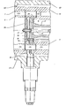
- the measuring insert shown in longitudinal section in Fig. 1 consists of an inlet part 1, which carries at its free end an outwardly projecting ring flange 2 with a groove 3 machined in its periphery, which lies in a sealing ring 4.
- the inlet part 1 is provided with passages 5 distributed over its circumference.
- An annular shoulder 6 is used to fasten the inlet part 1 with screws 7 on the end face of the outlet part 10 described below.
- a cup-shaped inlet body 8 with radially extending ribs 9 is inserted coaxially so that the open end of the inlet body 8 the outlet part 10 is facing; the inlet body 8 is the same length as the inlet part 1.
- the outlet part 10 is formed in one piece with an outlet body 11, to which it is connected by connecting webs 12, 13. It is widened in steps at the end facing the inlet part 1; the first extension for receiving the blades 29 of a turbine wheel 26 described below is intended and the second extension is adapted to the outer diameter of the associated end of the inlet part 1 so that the two ends overlap and the end face of the outlet part 10 on the annular shoulder 6 of the inlet part 1 comes across. In the overlap area, an annular groove 14 is machined into the outer wall of the outlet part 10 and a sealing ring 15 lies therein.
- the cup-shaped outlet body 11 extends into the area of the first extension; its open end faces the inlet body 8 and its closed end ends with the end of the outlet part 10. The outlet body 11 tapers from the area of the connecting web 12 to its closed end.
- the outlet part 10 is provided with a fastening flange 16 at the end facing away from the inlet part 1.
- a bearing housing 17 is inserted into the outlet body 11 from its open end, which is fastened to the end face of the outlet body 11 with a fastening flange 18 and screws 19.
- a shaft 20 runs through the bearing housing 17 and is rotatably mounted at one end of the bearing housing 17 in a bearing 21 and at the other end in the fastening flange 18.
- the bearing 21 has an axial pressure relief 22 provided, which is only indicated schematically and can for example be carried out hydraulically.
- the pressure medium line then runs through a plug 23 at the closed end of the bearing housing 17. In this way it is achieved that the rotation of the shaft 20 (and thus the function of the turbine wheel 26) is little influenced by pressure loads, in particular pressure surges, and practically from the installation position of the Measuring insert becomes independent.
- the shaft 20 is provided with a single-start worm 24, with which a worm wheel (not shown) meshes, which is connected via a transmission, also not shown, to an output member 25, which is rotatably mounted on the bearing housing 17 in alignment with the connecting web 12. Taps of this type are known and therefore do not require any further description.
- a turbine wheel 26 is wedged on an end of the shaft 20 projecting beyond the fastening flange 18 and secured with nuts 27.
- the turbine wheel 26 forms an edge 28 which springs back against the outlet body 11 and overlaps it over a short region of its length, the outer diameter of which is adapted to the outer diameter of the inlet body 8 and which carries blades 29 projecting therefrom which are received by the first extension in the outlet part 10 .
- Fig. 2 shows a partial section of a modified embodiment of the measuring insert described above; the same parts are provided with the same reference numerals.
- the inlet part 1, the outlet part 10, the outlet body 11 with the bearing housing 17 and the turbine wheel 26 with the blades 29 projecting from its edge 28 can be seen.
- the pulse generator 31 is inserted into the wall of the outlet part 10 in the region of the first extension , so that the pulse generator 31 does not interact with the brand carrier 30 applied to the turbine wheel 26, but rather directly with the blades 29.
- a flow channel 33 is formed between the inner wall of the inlet part 1 and the inner wall of the outlet part 10 on the one hand and the inlet body 8 and the outlet body 11 on the other hand, into which the blades 29 of the turbine wheel 26 extend and the is delimited in the area between the inlet body 8 and the outlet body 11 by the edge 28 of the turbine wheel 26.
- FIG. 3 shows a turbine gas meter after installation of the measuring insert described in connection with FIG. 1.
- the same parts are provided with the same reference numerals.
- the measuring insert is inserted into a pipe section 40 of the turbine gas meter, which is provided at both ends with connecting flanges 41 and carries a stop 42 in the form of an inwardly projecting ring at the outlet end.
- the measuring insert is inserted into the pipe section 40 and abuts against the stop 42 Screws 43 attached to the stop 42. It is then arranged so that a lateral extension 44 on the pipe section 40 with its bore 45 is aligned with a lateral passage of the measuring insert, which is formed by aligned bores in the outlet part 10, in the connecting web 12, in the outlet body 11 and in the bearing housing 17.
- the sealing ring 15 then lies against an annular shoulder 46 projecting against the measuring insert of the pipe section 40, while the sealing ring 4 rests against the inner wall of the pipe section 40 at its inlet end.
- the result is an axially delimited and sealed pressure space 47 between the measuring insert and the pipe section 40, which is connected via a connection 48 to a pressure measuring device and via the passages 5 in the inlet part 1 to the flow channel 33 and for measuring the serves static gas pressure in the line in which the turbine gas meter is installed.
- the lateral extension 44 carries a counter housing 50 with a counter 51 and a viewing window 52; the counter housing 50 also contains an interchangeable transmission gear 54 which is interposed between the counter 51 and the output member 53 of a magnetic coupling.
- the counter housing 50 is screwed to the side extension 44 in a sealing manner via a counter head 55.
- a transmission shaft 56 runs through the bore 45 of the side extension 44 and is coupled at one end to the driven member 25 on the bearing housing 17 and at the other end to the drive member 57 of the magnetic coupling. This creates a drive connection between the counter 51 and the shaft 20 of the turbine wheel 26, which is adapted to the respective measuring insert and indicates the flow of a certain gas volume through the flow channel 33 corresponding to a certain number of pulses from the pulse generator 31. The calibration of the turbine wheel gas meter is thus traced back to the calibration of the measuring insert.
- the measuring insert is calibrated in an officially approved test bench.
- the measuring insert is inserted into a corresponding pipe section with a counter.
- An air flow of known speed Q (m 3 / h) is passed through the test specimen over the length of a preselected time t (s); the static pressure P (mbar) at the connection 48, the barometric pressure b (mbar) and the temperature (° C.) of the air and the volume V of the air flowing through are measured by the display of the counter, and the number of pulses occurring at the pulse generator I determined.
- the volume Vp determined in this way is reduced to standard conditions (1 bar, 0 ° C.) and compared with the volume V N determined in a corresponding manner on a standard and reduced to standard conditions.
- a transmission gear 54 corresponding to the deviation is selected, which, when installed in the counter 51, compensates for the deviation in the counter display of the measuring insert tested on the test stand from the normal, so that the counter 51 provided with the tested measuring insert compensates for the same volume display as normal.
- a calibration certificate is then created, which contains, among other things, the number of pulses per m 3 and to which the above-mentioned transmission gear is added.
- the counter head 55 (and thus the counter housing 50, the counter 51, the existing transmission 54 and the output member 53) is first removed from the pipe section 40.
- the drive member 57 of the magnetic clutch and the transmission shaft 56 are removed.
- the screws 43 are loosened, and the measuring insert is removed from the Pipe section 40 removed.
- the measuring insert calibrated as described above is inserted into the pipe section 40 until it abuts the stop 42, if necessary with the aid of a press-in device, and then fastened to it with the screws 43.
- the pipe section 40 with the calibrated measuring insert is installed in the pipeline, the transmission shaft 56 is connected to the output member 25 on the bearing housing 17 and the drive member 57 of the magnetic coupling is reattached to the transmission shaft 56.
- the transmission gear 54 present in the counter 51 is exchanged for the transmission gear supplied with the calibrated measuring insert, the counter housing 50 is closed again and the counter head 55 is again attached to the side extension 44.
- the turbine gas meter is thus ready for operation again and is calibrated in that the connecting lines 32 are connected to an electronic meter. The number of pulses measured after passing through 1 m 3 must then correspond to the number of pulses per m 3 determined during the calibration.
- the counter used for this measuring insert has a suitable transmission ratio to the turbine wheel shaft and contains a counter gear set and an exchangeable transmission gear from an adjusting wheel set.
- the adjusting wheel set for the measuring insert consists of two gear wheels with 35 or 44 teeth.
Landscapes
- Physics & Mathematics (AREA)
- Fluid Mechanics (AREA)
- General Physics & Mathematics (AREA)
- Measuring Volume Flow (AREA)
- Measuring Fluid Pressure (AREA)
- Sampling And Sample Adjustment (AREA)
Priority Applications (5)
| Application Number | Priority Date | Filing Date | Title |
|---|---|---|---|
| AT81109360T ATE25144T1 (de) | 1981-10-30 | 1981-10-30 | Eichfaehiger turbinenradgaszaehler mit auswechselbarem messeinsatz. |
| DE8181109360T DE3175857D1 (en) | 1981-10-30 | 1981-10-30 | Calibratable gas turbine motor with interchangeable measuring unit |
| EP81109360A EP0078334B1 (fr) | 1981-10-30 | 1981-10-30 | Compteur à gaz à turbine avec possibilité d'étalonnage et à élément de mesure échangeable |
| US06/406,093 US4463613A (en) | 1981-10-30 | 1982-08-06 | Calibratable turbine wheel gas meter with exchangeable measuring insert |
| JP57189356A JPS5883217A (ja) | 1981-10-30 | 1982-10-29 | タ−ビン車型ガスメ−タ |
Applications Claiming Priority (1)
| Application Number | Priority Date | Filing Date | Title |
|---|---|---|---|
| EP81109360A EP0078334B1 (fr) | 1981-10-30 | 1981-10-30 | Compteur à gaz à turbine avec possibilité d'étalonnage et à élément de mesure échangeable |
Publications (2)
| Publication Number | Publication Date |
|---|---|
| EP0078334A1 true EP0078334A1 (fr) | 1983-05-11 |
| EP0078334B1 EP0078334B1 (fr) | 1987-01-21 |
Family
ID=8187987
Family Applications (1)
| Application Number | Title | Priority Date | Filing Date |
|---|---|---|---|
| EP81109360A Expired EP0078334B1 (fr) | 1981-10-30 | 1981-10-30 | Compteur à gaz à turbine avec possibilité d'étalonnage et à élément de mesure échangeable |
Country Status (5)
| Country | Link |
|---|---|
| US (1) | US4463613A (fr) |
| EP (1) | EP0078334B1 (fr) |
| JP (1) | JPS5883217A (fr) |
| AT (1) | ATE25144T1 (fr) |
| DE (1) | DE3175857D1 (fr) |
Cited By (1)
| Publication number | Priority date | Publication date | Assignee | Title |
|---|---|---|---|---|
| WO2017144155A1 (fr) * | 2016-02-24 | 2017-08-31 | Kracht Gmbh | Débitmètre |
Families Citing this family (19)
| Publication number | Priority date | Publication date | Assignee | Title |
|---|---|---|---|---|
| DE3521410A1 (de) * | 1985-06-14 | 1986-12-18 | Johann Baptist Rombach Gmbh & Co Kg, 7500 Karlsruhe | Turbinenradzaehler |
| US4658634A (en) * | 1986-02-11 | 1987-04-21 | Piedmont Natural Gas Company | Meter prover |
| US4674316A (en) * | 1986-04-21 | 1987-06-23 | The Singer Company | Calibration system for mechanical gas volume corrector |
| JPH0634652Y2 (ja) * | 1989-03-22 | 1994-09-07 | 矢崎総業株式会社 | ユニット式ハイブリッドガスメータ |
| JPH0794995B2 (ja) * | 1990-09-07 | 1995-10-11 | 東京瓦斯株式会社 | 気体用タービンメータ |
| US5473932A (en) * | 1991-11-07 | 1995-12-12 | M & Fc Holding Company, Inc. | Tandem rotor turbine meter and field calibration module |
| US5939645A (en) * | 1997-04-17 | 1999-08-17 | Nielsen-Kellerman | Vane anemometer having a modular impeller assembly |
| US6257074B1 (en) | 1997-04-17 | 2001-07-10 | Nielsen-Kellerman Co. | Vane anemometer with thermally isolated sensors |
| US5783753A (en) * | 1997-04-17 | 1998-07-21 | Nielsen-Kellerman Company | Vane anemometer having a modular impeller assembly |
| US5877430A (en) * | 1997-06-13 | 1999-03-02 | M&Fc Holding Company, Inc. | Pressure measuring system for gas flow meter |
| DE19920393B4 (de) * | 1999-05-04 | 2009-09-24 | Elster Gmbh | Anordnung zum Bestimmen eines Volumens eines Gasstroms |
| USD461421S1 (en) | 2001-03-30 | 2002-08-13 | Richard Kellerman | Vane anemometer |
| NL1022963C2 (nl) * | 2003-03-18 | 2004-09-23 | Instromet Bv | Turbinemeter. |
| US7637172B2 (en) * | 2006-09-19 | 2009-12-29 | Mattel, Inc. | Electronic device with speed measurement and output generation |
| PL211598B1 (pl) * | 2008-07-08 | 2012-06-29 | Apator Metrix Społka Akcyjna | Liczydło elektroniczne |
| DE102014106927A1 (de) * | 2014-05-16 | 2015-11-19 | Endress + Hauser Flowtec Ag | Messgerät, insbesondere Durchflussmessgerät, und Verfahren zur zur Herstellung eines Messrohres für ein Messgerät |
| CN106123989B (zh) * | 2016-08-31 | 2023-12-08 | 温岭甬岭水表有限公司 | 一种多流远传水表 |
| CN107238424B (zh) * | 2017-06-26 | 2018-10-09 | 福州市长乐区三互信息科技有限公司 | 一种循环式气体涡轮流量计的检测装置及检测方法 |
| CN115638837B (zh) * | 2022-10-24 | 2025-11-04 | 重庆前卫表业有限公司 | 通用型涡轮流量计 |
Citations (5)
| Publication number | Priority date | Publication date | Assignee | Title |
|---|---|---|---|---|
| FR1288912A (fr) * | 1961-02-17 | 1962-03-30 | Soc Et Propulsion Par Reaction | Débitmètre |
| US3695106A (en) * | 1970-07-02 | 1972-10-03 | Daniel Ind Inc | Gas turbine meter |
| DE2702319A1 (de) * | 1977-01-21 | 1978-07-27 | Elster Ag | Turbinenradzaehler |
| GB2002856A (en) * | 1977-08-20 | 1979-02-28 | Meinecke Ag | Turbine type flow meters |
| DE2829866A1 (de) * | 1978-07-07 | 1980-01-24 | Elster Ag | Schraubenradzaehler |
Family Cites Families (7)
| Publication number | Priority date | Publication date | Assignee | Title |
|---|---|---|---|---|
| DE728132C (de) * | 1937-01-23 | 1942-11-20 | Hydrometer Ag | Woltmannmesser fuer Fluessigkeiten |
| US3364743A (en) * | 1965-09-28 | 1968-01-23 | Neptune Meter Co | Turbine flowmeter |
| US3623835A (en) * | 1969-06-11 | 1971-11-30 | Halliburton Co | Gas flowmeter |
| US3707872A (en) * | 1971-05-10 | 1973-01-02 | Gamon Calmet Ind Inc | Compound fluid meter |
| SE351291B (fr) * | 1971-06-11 | 1972-11-20 | Saab Scania Ab | |
| JPS5840127B2 (ja) * | 1980-01-19 | 1983-09-03 | 株式会社 東京量水器工業所 | 流量計器差測定方法及び装置 |
| IT1397174B1 (it) * | 2009-10-27 | 2013-01-04 | F I A M M Spa | Metodo per la rilevazione continua dell'efficienza di una batteria specie di una batteria installata in autoveicoli e dispositivo utilizzante tale metodo |
-
1981
- 1981-10-30 DE DE8181109360T patent/DE3175857D1/de not_active Expired
- 1981-10-30 EP EP81109360A patent/EP0078334B1/fr not_active Expired
- 1981-10-30 AT AT81109360T patent/ATE25144T1/de not_active IP Right Cessation
-
1982
- 1982-08-06 US US06/406,093 patent/US4463613A/en not_active Expired - Lifetime
- 1982-10-29 JP JP57189356A patent/JPS5883217A/ja active Granted
Patent Citations (5)
| Publication number | Priority date | Publication date | Assignee | Title |
|---|---|---|---|---|
| FR1288912A (fr) * | 1961-02-17 | 1962-03-30 | Soc Et Propulsion Par Reaction | Débitmètre |
| US3695106A (en) * | 1970-07-02 | 1972-10-03 | Daniel Ind Inc | Gas turbine meter |
| DE2702319A1 (de) * | 1977-01-21 | 1978-07-27 | Elster Ag | Turbinenradzaehler |
| GB2002856A (en) * | 1977-08-20 | 1979-02-28 | Meinecke Ag | Turbine type flow meters |
| DE2829866A1 (de) * | 1978-07-07 | 1980-01-24 | Elster Ag | Schraubenradzaehler |
Cited By (1)
| Publication number | Priority date | Publication date | Assignee | Title |
|---|---|---|---|---|
| WO2017144155A1 (fr) * | 2016-02-24 | 2017-08-31 | Kracht Gmbh | Débitmètre |
Also Published As
| Publication number | Publication date |
|---|---|
| JPS6335924B2 (fr) | 1988-07-18 |
| ATE25144T1 (de) | 1987-02-15 |
| JPS5883217A (ja) | 1983-05-19 |
| EP0078334B1 (fr) | 1987-01-21 |
| US4463613A (en) | 1984-08-07 |
| DE3175857D1 (en) | 1987-02-26 |
Similar Documents
| Publication | Publication Date | Title |
|---|---|---|
| EP0078334B1 (fr) | Compteur à gaz à turbine avec possibilité d'étalonnage et à élément de mesure échangeable | |
| DE1935989B2 (de) | Differentialdruckstroemungssonden zum einsatz in eine fliessfaehiges medium fuehrende rohrleitung | |
| EP2375224A1 (fr) | Dispositif de mesure des ultrasons et procédé de mesure de la vitesse d'écoulement d'un liquide | |
| DE3408779A1 (de) | Einstellbarer, laminarer durchflussmesser | |
| EP3732388A1 (fr) | Tuyau pour un transducteur, transducteur comprenant un tuyau de ce type et système de mesure ainsi formé | |
| DE2705795C2 (fr) | ||
| EP3015829A1 (fr) | Debitmetre helicoïdal | |
| DE102017001049A1 (de) | Wirkdruckgeber | |
| DE68909050T2 (de) | Abnutzungsdetektionsvorrichtung für Schmieröl. | |
| DE102004048765A1 (de) | Verbund-System, Verfahren zu dessen Herstellung sowie Messaufnehmer mit einem solchen Verbund-System | |
| DE2821711C2 (fr) | ||
| EP1068467A1 (fr) | Dispositif pour le montage ulterieur d'un debitmetre dans une canalisation | |
| DE3050884C2 (de) | Einrichtung zur Justierung von Funktionsteilen einer Gas- oder Flüssigkeitsmeßeinrichtung | |
| EP2072970A1 (fr) | Procédé destiné à la détermination de la viscosité d'un liquide avec un débitmètre à tourbillons | |
| DE2141243A1 (de) | Verfahren und Vorrichtung zum Erfassen des Verschmutzungsgrades von Strömungsmitteln, insbesondere Flüssigkeiten | |
| DE2745609C2 (de) | Vorrichtung zum Messen strömender Medien, insbesondere zum Bestimmen der Menge einer in einem Leitungssystem unter Druck strömenden Flüssigkeit | |
| DE2536172A1 (de) | Volumenmessgeraet | |
| EP0943901B1 (fr) | Raccord pour un dispositif de mesure de débit d'un liquide | |
| EP0650058B1 (fr) | Moteur à flasque-bride avec dispositif de mesure pour la détection de la rotation d'arbre du moteur | |
| EP2241864B1 (fr) | Dispositif de mesure du débit d'un fluid avec un dispositif de liaison pour le capteur | |
| DE3710968A1 (de) | Vorrichtung zur messung des volumen- oder massenstromes | |
| EP0183987A1 (fr) | Dispositif pour la mesure du débit dans une installation de climatisation | |
| EP1898134A2 (fr) | Dispositif de restriction pour installations de chauffage et de refroidissement | |
| DE102004055101A1 (de) | Baueinheit aus einem Strömungssensor, einem Durchlaßkanal und einem innerhalb des Durchlaßkanals angeordneten Meßkanals | |
| DE1548881C3 (de) | DurchfluBmesser für strömende Medien |
Legal Events
| Date | Code | Title | Description |
|---|---|---|---|
| PUAI | Public reference made under article 153(3) epc to a published international application that has entered the european phase |
Free format text: ORIGINAL CODE: 0009012 |
|
| 17P | Request for examination filed |
Effective date: 19811030 |
|
| AK | Designated contracting states |
Designated state(s): AT BE CH DE FR GB IT LI LU NL SE |
|
| GRAA | (expected) grant |
Free format text: ORIGINAL CODE: 0009210 |
|
| AK | Designated contracting states |
Kind code of ref document: B1 Designated state(s): AT BE CH DE FR GB IT LI LU NL SE |
|
| REF | Corresponds to: |
Ref document number: 25144 Country of ref document: AT Date of ref document: 19870215 Kind code of ref document: T |
|
| PG25 | Lapsed in a contracting state [announced via postgrant information from national office to epo] |
Ref country code: SE Effective date: 19870131 |
|
| REF | Corresponds to: |
Ref document number: 3175857 Country of ref document: DE Date of ref document: 19870226 |
|
| ET | Fr: translation filed | ||
| ITF | It: translation for a ep patent filed | ||
| PG25 | Lapsed in a contracting state [announced via postgrant information from national office to epo] |
Ref country code: AT Effective date: 19871030 |
|
| PG25 | Lapsed in a contracting state [announced via postgrant information from national office to epo] |
Ref country code: LU Free format text: LAPSE BECAUSE OF NON-PAYMENT OF DUE FEES Effective date: 19871031 Ref country code: LI Effective date: 19871031 Ref country code: CH Effective date: 19871031 |
|
| PLBE | No opposition filed within time limit |
Free format text: ORIGINAL CODE: 0009261 |
|
| STAA | Information on the status of an ep patent application or granted ep patent |
Free format text: STATUS: NO OPPOSITION FILED WITHIN TIME LIMIT |
|
| 26N | No opposition filed | ||
| REG | Reference to a national code |
Ref country code: CH Ref legal event code: PL |
|
| PGFP | Annual fee paid to national office [announced via postgrant information from national office to epo] |
Ref country code: BE Payment date: 19891109 Year of fee payment: 9 |
|
| PGFP | Annual fee paid to national office [announced via postgrant information from national office to epo] |
Ref country code: LU Payment date: 19891123 Year of fee payment: 9 |
|
| PG25 | Lapsed in a contracting state [announced via postgrant information from national office to epo] |
Ref country code: BE Effective date: 19901031 |
|
| BERE | Be: lapsed |
Owner name: ELSTER & AG MESS- UND REGELTECHNIK Effective date: 19901031 |
|
| ITTA | It: last paid annual fee | ||
| PGFP | Annual fee paid to national office [announced via postgrant information from national office to epo] |
Ref country code: GB Payment date: 19990913 Year of fee payment: 19 |
|
| PGFP | Annual fee paid to national office [announced via postgrant information from national office to epo] |
Ref country code: FR Payment date: 19990920 Year of fee payment: 19 |
|
| PGFP | Annual fee paid to national office [announced via postgrant information from national office to epo] |
Ref country code: NL Payment date: 19990923 Year of fee payment: 19 |
|
| PGFP | Annual fee paid to national office [announced via postgrant information from national office to epo] |
Ref country code: DE Payment date: 19990927 Year of fee payment: 19 |
|
| PG25 | Lapsed in a contracting state [announced via postgrant information from national office to epo] |
Ref country code: GB Free format text: LAPSE BECAUSE OF NON-PAYMENT OF DUE FEES Effective date: 20001030 |
|
| PG25 | Lapsed in a contracting state [announced via postgrant information from national office to epo] |
Ref country code: NL Free format text: LAPSE BECAUSE OF NON-PAYMENT OF DUE FEES Effective date: 20010501 |
|
| GBPC | Gb: european patent ceased through non-payment of renewal fee |
Effective date: 20001030 |
|
| PG25 | Lapsed in a contracting state [announced via postgrant information from national office to epo] |
Ref country code: FR Free format text: LAPSE BECAUSE OF NON-PAYMENT OF DUE FEES Effective date: 20010629 |
|
| NLV4 | Nl: lapsed or anulled due to non-payment of the annual fee |
Effective date: 20010501 |
|
| PG25 | Lapsed in a contracting state [announced via postgrant information from national office to epo] |
Ref country code: DE Free format text: LAPSE BECAUSE OF NON-PAYMENT OF DUE FEES Effective date: 20010703 |
|
| REG | Reference to a national code |
Ref country code: FR Ref legal event code: ST |