EP0078496A1 - Pneumatikzylinder - Google Patents
Pneumatikzylinder Download PDFInfo
- Publication number
- EP0078496A1 EP0078496A1 EP82109913A EP82109913A EP0078496A1 EP 0078496 A1 EP0078496 A1 EP 0078496A1 EP 82109913 A EP82109913 A EP 82109913A EP 82109913 A EP82109913 A EP 82109913A EP 0078496 A1 EP0078496 A1 EP 0078496A1
- Authority
- EP
- European Patent Office
- Prior art keywords
- piston
- cylinder
- extension
- cylinder according
- stroke
- Prior art date
- Legal status (The legal status is an assumption and is not a legal conclusion. Google has not performed a legal analysis and makes no representation as to the accuracy of the status listed.)
- Granted
Links
- 229910000831 Steel Inorganic materials 0.000 claims description 4
- 239000010959 steel Substances 0.000 claims description 4
- 238000013016 damping Methods 0.000 claims description 2
- 230000011664 signaling Effects 0.000 claims 1
- 238000007789 sealing Methods 0.000 description 2
- 238000011161 development Methods 0.000 description 1
- 230000018109 developmental process Effects 0.000 description 1
Images
Classifications
-
- F—MECHANICAL ENGINEERING; LIGHTING; HEATING; WEAPONS; BLASTING
- F15—FLUID-PRESSURE ACTUATORS; HYDRAULICS OR PNEUMATICS IN GENERAL
- F15B—SYSTEMS ACTING BY MEANS OF FLUIDS IN GENERAL; FLUID-PRESSURE ACTUATORS, e.g. SERVOMOTORS; DETAILS OF FLUID-PRESSURE SYSTEMS, NOT OTHERWISE PROVIDED FOR
- F15B15/00—Fluid-actuated devices for displacing a member from one position to another; Gearing associated therewith
- F15B15/20—Other details, e.g. assembly with regulating devices
- F15B15/24—Other details, e.g. assembly with regulating devices for restricting the stroke
-
- F—MECHANICAL ENGINEERING; LIGHTING; HEATING; WEAPONS; BLASTING
- F15—FLUID-PRESSURE ACTUATORS; HYDRAULICS OR PNEUMATICS IN GENERAL
- F15B—SYSTEMS ACTING BY MEANS OF FLUIDS IN GENERAL; FLUID-PRESSURE ACTUATORS, e.g. SERVOMOTORS; DETAILS OF FLUID-PRESSURE SYSTEMS, NOT OTHERWISE PROVIDED FOR
- F15B15/00—Fluid-actuated devices for displacing a member from one position to another; Gearing associated therewith
- F15B15/08—Characterised by the construction of the motor unit
- F15B15/082—Characterised by the construction of the motor unit the motor being of the slotted cylinder type
Definitions
- the invention relates to a pneumatic cylinder according to the preamble of the main claim.
- the stroke is limited by the housing cover arranged at the ends of the cylinder tube, i.e. the piston stroke is always constant.
- the pneumatic cylinder according to the invention has the advantage that the piston stroke can be freely selected. This significantly improves the range of applications for this pneumatic cylinder.
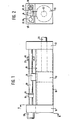
- FIG. 1 shows a side view of a pneumatic cylinder, in FIG. 2 a section along II of FIG. 1.
- 10 denotes the cylinder tube of a pneumatic cylinder, which is closed on both sides by covers 11, 12.
- a piston 13 is slidably mounted in the cylinder tube 10, to which an extension 14 is fastened, which projects outwards through a longitudinal slot formed in the cylinder tube. Sealing to the outside takes place via a band-shaped sealing strip 15.
- Such pneumatic cylinders are known, e.g. from DE-OS 21 62 572, and therefore not described further.
- Two stops 17, 18, which cooperate with the extension 14, serve to adjust the stroke or limit the stroke of the piston 13.
- the stops 17, 18 are arranged so as to be displaceable on spindles 19, 19 'which are coaxial with the cylinder tube 10.
- the stops can be moved by hand, for example, or the spindles can be designed as threaded spindles which are driven by drive motors 20, 20 ', expediently by electric motors or any stepping motors.
- the stops then have a corresponding internal thread. If the stroke should only be adjusted in one direction, then of course only one spindle with a stop and a motor is required.
- a toothed belt or a steel belt for a fixed resolver on the extension 14 or to provide sensors for a fixed coded scale or a coded steel belt with fixed sensors.
- any damping device 21, 22 on the stops can consist of a rubber buffer.
- the stops can of course also be adjusted and clamped by hand.
- the pneumatic cylinder can, but need not, be equipped with an outwardly projecting piston rod 22. Usually, however, the force of such a cylinder is tapped at the extension 14.
Landscapes
- Engineering & Computer Science (AREA)
- Physics & Mathematics (AREA)
- Fluid Mechanics (AREA)
- Mechanical Engineering (AREA)
- General Engineering & Computer Science (AREA)
- Actuator (AREA)
- Pistons, Piston Rings, And Cylinders (AREA)
Abstract
Description
- Stand der Technik und Vorteile der Erfindung
- Die Erfindung geht aus von einem Pneumatikzylinder nach der Gattung des Hauptanspruchs. Bei diesem bekannten Pneumatikzylinder wird der-Hub begrenzt durch die an den Enden des Zylinderrohrs angeordneten Gehäusedeckel, d.h. der Kolbenhub ist stets konstant.
- Demgegenüber hat der erfindungsgemäße Pneumatikzylinder den Vorteil, daß der Kolbenhub frei wählbar ist. Dadurch verbessert sich das Einsatzspektrum dieses Pneumatikzylinders wesentlich.
- Durch die in den Unteransprüchen aufgeführten Maßnahmen sind vorteilhafte Weiterbildungen und Verbesserungen der im Hauptanspruch angegebenen Merkmale möglich.
- Diese zeigt in Figur 1 eine Seitenansicht eines Pneumatikzylinders, in Figur 2 einen Schnitt nach II von Figur 1.
- In Figur 1 ist mit 10 das Zylinderrohr eines Pneumatikzylinders bezeichnet, das beidseitig durch Deckel 11, 12 verschlossen ist. Im Zylinderrohr 10 ist ein Kolben 13 gleitend gelagert, an dem ein Fortsatz 14 befestigt ist, welcher durch einen im Zylinderrohr ausgebildeten Längsschlitz nach außen ragt. Die Abdichtung nach außen erfolgt über einen bandförmigen Dichtstreifen 15. Derartige Pneumatikzylinder sind bekannt, z.B. aus der DE-OS 21 62 572, und deshalb nicht weiter beschrieben. Zur Hubeinstellung bzw. zur Hubbegrenzung des Kolbens 13 dienen zwei Anschläge 17, 18, die mit dem Fortsatz 14 zusammenwirken. Die Anschläge 17, 18 sind auf achsgleich zum Zylinderrohr 10--verlaufenden Spindeln 19, 19' verschiebbar angeordnet. Die Anschläge können beispielsweise von Hand verschoben werden oder es können die Spindeln als Gewindespindeln ausgebildet sein, die von Antriebsmotoren 20, 20' angetrieben sind, zweckmäßigerweise von Elektromotoren oder beliebigen Schrittmotoren. Die Anschläge haben dann ein entsprechendes Innengewinde. Soll die Hubeinstellung nur in einer Richtung erfolgen, so ist selbstverständlich nur eine Spindel mit einem Anschlag und einem Motor erforderlich.
- Zur Positionsmeldung des Kolbens bzw. des Fortsatzes ist es zweckmäßig, am Fortsatz 14 beispielsweise einen Zahnriemen oder ein Stahlband zu einem festen Drehmelder anzuordnen bzw. Sensoren für einen feststehenden codierten Maßstab oder ein codiertes Stahlband mit feststehenden Sensoren vorzusehen.
- Zweckmäßig ist es, an den Anschlägen eine beliebige Dämpfungseinrichtung 21, 22 vorzusehen. Diese kann im einfachsten Fall aus einem Gummipuffer bestehen. Die Anschläge können selbstverständlich auch von Hand verstellt und festgeklemmt werden.
- Der Pneumatikzylinder kann, muß aber nicht, mit einer nach außen ragenden Kolbenstange 22 ausgestattet sein. Üblicherweise erfolgt aber der Kraftabgriff eines derartigen Zylinders am Fortsatz 14.
Claims (7)
Applications Claiming Priority (2)
| Application Number | Priority Date | Filing Date | Title |
|---|---|---|---|
| DE8131711 | 1981-10-30 | ||
| DE8131711U | 1981-10-30 |
Publications (2)
| Publication Number | Publication Date |
|---|---|
| EP0078496A1 true EP0078496A1 (de) | 1983-05-11 |
| EP0078496B1 EP0078496B1 (de) | 1985-03-27 |
Family
ID=6732567
Family Applications (1)
| Application Number | Title | Priority Date | Filing Date |
|---|---|---|---|
| EP82109913A Expired EP0078496B1 (de) | 1981-10-30 | 1982-10-27 | Pneumatikzylinder |
Country Status (2)
| Country | Link |
|---|---|
| EP (1) | EP0078496B1 (de) |
| DE (1) | DE3262822D1 (de) |
Cited By (14)
| Publication number | Priority date | Publication date | Assignee | Title |
|---|---|---|---|---|
| EP0095246A1 (de) * | 1982-05-21 | 1983-11-30 | James Burn Bindings Limited | Vorrichtung zum linearen Steuern |
| EP0124845A1 (de) * | 1983-05-10 | 1984-11-14 | I.M.F. Industria Macchine Faenza S.P.A. | Vorrichtung zum Einstellen einer Bearbeitungseinheit in Beziehung zu einem Werkstück, insbesondere für eine Fertigungsstrasse |
| EP0127854A1 (de) * | 1983-06-02 | 1984-12-12 | TEKMA KINOMAT S.p.A. | Werkstückpostioniereinrichtung für Maschinen |
| EP0346504A1 (de) * | 1988-06-11 | 1989-12-20 | Festo KG | Kolbenstangenlose Kolben-Zylinder-Anordnung mit einer Vorrichtung zur Hubbegrenzung |
| EP0450108A1 (de) * | 1990-03-31 | 1991-10-09 | Honeywell B.V. | Vorrichtung zur Hubbegrenzung |
| US5065663A (en) * | 1989-12-18 | 1991-11-19 | Siemens Aktiengesellschaft | Electropneumatic or electrohydraulic linear drive mechanism |
| US5181468A (en) * | 1990-04-26 | 1993-01-26 | Bobst Sa | Pretensioned jack for controlling the operating pressure between two rotary cylinders |
| US5188018A (en) * | 1990-08-28 | 1993-02-23 | Montech Ag | Linear unit with displaceable ball bearing assembly |
| GB2309747A (en) * | 1996-02-03 | 1997-08-06 | Hytek Tech Int | Fluid-pressure-operated actuators |
| KR20030069687A (ko) * | 2002-02-22 | 2003-08-27 | 한국기계연구원 | 다단 위치 제어 실린더 |
| EP1186785A3 (de) * | 2000-09-12 | 2004-01-07 | Bosch Rexroth Teknik AB | Kolbenstangenloses Stellglied mit Positioniermodul |
| EP1700819A3 (de) * | 2005-03-08 | 2009-08-19 | Khs Ag | Betätigungselement sowie Füllmaschine mit derartigen Betätigungselementen |
| EP2028378A3 (de) * | 2007-08-23 | 2010-05-05 | Tokyo Electron Limited | Mechanismus zum Verändern der Endlage eines Zylinders und Substratverarbeitungsvorrichtung damit |
| CN114810716A (zh) * | 2022-04-24 | 2022-07-29 | 合肥志必达液压科技有限公司 | 一种液压油缸活塞系统 |
Citations (3)
| Publication number | Priority date | Publication date | Assignee | Title |
|---|---|---|---|---|
| FR1596551A (de) * | 1968-07-31 | 1970-06-22 | ||
| FR2444828A1 (fr) * | 1978-12-18 | 1980-07-18 | Heurtey Metallurgie | Perfectionnements apportes aux verins |
| DE2908605A1 (de) * | 1979-03-05 | 1980-09-11 | Geb Kotz Rosa Mueller | Pneumatische lineareinheit mit zylindern ohne kolbenstange |
-
1982
- 1982-10-27 EP EP82109913A patent/EP0078496B1/de not_active Expired
- 1982-10-27 DE DE8282109913T patent/DE3262822D1/de not_active Expired
Patent Citations (3)
| Publication number | Priority date | Publication date | Assignee | Title |
|---|---|---|---|---|
| FR1596551A (de) * | 1968-07-31 | 1970-06-22 | ||
| FR2444828A1 (fr) * | 1978-12-18 | 1980-07-18 | Heurtey Metallurgie | Perfectionnements apportes aux verins |
| DE2908605A1 (de) * | 1979-03-05 | 1980-09-11 | Geb Kotz Rosa Mueller | Pneumatische lineareinheit mit zylindern ohne kolbenstange |
Cited By (15)
| Publication number | Priority date | Publication date | Assignee | Title |
|---|---|---|---|---|
| EP0095246A1 (de) * | 1982-05-21 | 1983-11-30 | James Burn Bindings Limited | Vorrichtung zum linearen Steuern |
| EP0124845A1 (de) * | 1983-05-10 | 1984-11-14 | I.M.F. Industria Macchine Faenza S.P.A. | Vorrichtung zum Einstellen einer Bearbeitungseinheit in Beziehung zu einem Werkstück, insbesondere für eine Fertigungsstrasse |
| EP0127854A1 (de) * | 1983-06-02 | 1984-12-12 | TEKMA KINOMAT S.p.A. | Werkstückpostioniereinrichtung für Maschinen |
| EP0346504A1 (de) * | 1988-06-11 | 1989-12-20 | Festo KG | Kolbenstangenlose Kolben-Zylinder-Anordnung mit einer Vorrichtung zur Hubbegrenzung |
| US5065663A (en) * | 1989-12-18 | 1991-11-19 | Siemens Aktiengesellschaft | Electropneumatic or electrohydraulic linear drive mechanism |
| US5108072A (en) * | 1990-03-31 | 1992-04-28 | Honeywell Inc. | Variable pressure electrically operated valve with an adjustable stroke-limiting mechanism for the actuator |
| EP0450108A1 (de) * | 1990-03-31 | 1991-10-09 | Honeywell B.V. | Vorrichtung zur Hubbegrenzung |
| US5181468A (en) * | 1990-04-26 | 1993-01-26 | Bobst Sa | Pretensioned jack for controlling the operating pressure between two rotary cylinders |
| US5188018A (en) * | 1990-08-28 | 1993-02-23 | Montech Ag | Linear unit with displaceable ball bearing assembly |
| GB2309747A (en) * | 1996-02-03 | 1997-08-06 | Hytek Tech Int | Fluid-pressure-operated actuators |
| EP1186785A3 (de) * | 2000-09-12 | 2004-01-07 | Bosch Rexroth Teknik AB | Kolbenstangenloses Stellglied mit Positioniermodul |
| KR20030069687A (ko) * | 2002-02-22 | 2003-08-27 | 한국기계연구원 | 다단 위치 제어 실린더 |
| EP1700819A3 (de) * | 2005-03-08 | 2009-08-19 | Khs Ag | Betätigungselement sowie Füllmaschine mit derartigen Betätigungselementen |
| EP2028378A3 (de) * | 2007-08-23 | 2010-05-05 | Tokyo Electron Limited | Mechanismus zum Verändern der Endlage eines Zylinders und Substratverarbeitungsvorrichtung damit |
| CN114810716A (zh) * | 2022-04-24 | 2022-07-29 | 合肥志必达液压科技有限公司 | 一种液压油缸活塞系统 |
Also Published As
| Publication number | Publication date |
|---|---|
| DE3262822D1 (en) | 1985-05-02 |
| EP0078496B1 (de) | 1985-03-27 |
Similar Documents
| Publication | Publication Date | Title |
|---|---|---|
| EP0078496A1 (de) | Pneumatikzylinder | |
| DE3609605C2 (de) | ||
| DE2806117C2 (de) | Elektrisch betätigbarer Fensterantrieb, insbesondere für Kraftfahrzeuge | |
| EP0591621B1 (de) | Dreh-Linear-Einheit | |
| DE3319522C2 (de) | Druckmittelbetätigte Kolben-Zylinder-Einheit | |
| DE3244616C2 (de) | Vorrichtung zur Messung von Vorschubbewegungen | |
| DE3227245C2 (de) | ||
| EP0532720A1 (de) | Druckmittelbetätigte lineareinheit. | |
| DE4408639C2 (de) | Arbeitszylinder mit einem Zylindergehäuseprofil | |
| EP0268030B1 (de) | Potentiometer bzw. veränderbarer Widerstand | |
| DE4020368A1 (de) | Arbeitszylinder | |
| DE4206751A1 (de) | Linearantrieb | |
| EP0297150B1 (de) | Positionsdetektor für das bewegbare Teil eines mit Fluid betätigten Stellgliedes | |
| DE4137881C2 (de) | Vorrichtung zum Erfassen und Verstellen der Lage eines Bauteils | |
| DE2609649C3 (de) | Anschlagvorrichtung | |
| DE8131711U1 (de) | Pneumatikzylinder | |
| DE19545923A1 (de) | Einrichtung mit einem Zylinder, einem in diesem verschiebbaren Kolben und einem im Zylinder angeordneten, induktiven Meßwandler | |
| DE3324584A1 (de) | Einrichtung zum feststellen einer relativen verschiebelage | |
| DE2407989C2 (de) | Arbeitszylinder für pneumatische oder hydraulische Druckmedien | |
| DE4105702C2 (de) | ||
| DE3139638C2 (de) | Zylinder mit Kolben und Kolbenstange für Steuer-oder Regelzwecke | |
| DE3438178C2 (de) | ||
| DE8315785U1 (de) | Druckmittelbetätigte Kolben-Zylinder-Einheit mit Magnetschuh als Verdrehsicherung | |
| DE102016207982A1 (de) | Stellvorrichtung | |
| DE10026082C1 (de) | Vorrichtung zur Befestigung eines Sensors an einem Druckmittelzylinder |
Legal Events
| Date | Code | Title | Description |
|---|---|---|---|
| PUAI | Public reference made under article 153(3) epc to a published international application that has entered the european phase |
Free format text: ORIGINAL CODE: 0009012 |
|
| 17P | Request for examination filed |
Effective date: 19821027 |
|
| AK | Designated contracting states |
Designated state(s): CH DE FR GB IT LI SE |
|
| ITF | It: translation for a ep patent filed | ||
| GRAA | (expected) grant |
Free format text: ORIGINAL CODE: 0009210 |
|
| AK | Designated contracting states |
Designated state(s): CH DE FR GB IT LI SE |
|
| REF | Corresponds to: |
Ref document number: 3262822 Country of ref document: DE Date of ref document: 19850502 |
|
| ET | Fr: translation filed | ||
| PLBI | Opposition filed |
Free format text: ORIGINAL CODE: 0009260 |
|
| 26 | Opposition filed |
Opponent name: WABCO WESTINGHOUSE FAHRZEUGBREMSEN GMBH Effective date: 19851221 |
|
| PLBN | Opposition rejected |
Free format text: ORIGINAL CODE: 0009273 |
|
| STAA | Information on the status of an ep patent application or granted ep patent |
Free format text: STATUS: OPPOSITION REJECTED |
|
| 27O | Opposition rejected |
Effective date: 19880805 |
|
| ITTA | It: last paid annual fee | ||
| PGFP | Annual fee paid to national office [announced via postgrant information from national office to epo] |
Ref country code: SE Payment date: 19920929 Year of fee payment: 11 |
|
| PGFP | Annual fee paid to national office [announced via postgrant information from national office to epo] |
Ref country code: GB Payment date: 19921016 Year of fee payment: 11 |
|
| PGFP | Annual fee paid to national office [announced via postgrant information from national office to epo] |
Ref country code: FR Payment date: 19921023 Year of fee payment: 11 |
|
| PGFP | Annual fee paid to national office [announced via postgrant information from national office to epo] |
Ref country code: DE Payment date: 19921221 Year of fee payment: 11 |
|
| PGFP | Annual fee paid to national office [announced via postgrant information from national office to epo] |
Ref country code: CH Payment date: 19930127 Year of fee payment: 11 |
|
| PG25 | Lapsed in a contracting state [announced via postgrant information from national office to epo] |
Ref country code: GB Effective date: 19931027 |
|
| PG25 | Lapsed in a contracting state [announced via postgrant information from national office to epo] |
Ref country code: SE Effective date: 19931028 |
|
| PG25 | Lapsed in a contracting state [announced via postgrant information from national office to epo] |
Ref country code: LI Effective date: 19931031 Ref country code: CH Effective date: 19931031 |
|
| GBPC | Gb: european patent ceased through non-payment of renewal fee |
Effective date: 19931027 |
|
| PG25 | Lapsed in a contracting state [announced via postgrant information from national office to epo] |
Ref country code: FR Effective date: 19940630 |
|
| REG | Reference to a national code |
Ref country code: CH Ref legal event code: PL |
|
| PG25 | Lapsed in a contracting state [announced via postgrant information from national office to epo] |
Ref country code: DE Effective date: 19940701 |
|
| REG | Reference to a national code |
Ref country code: FR Ref legal event code: ST |
|
| EUG | Se: european patent has lapsed |
Ref document number: 82109913.2 Effective date: 19940510 |
|
| APAH | Appeal reference modified |
Free format text: ORIGINAL CODE: EPIDOSCREFNO |