EP0078622A2 - Dauerhafte Fersen- und Seitenteile eines Schuhs - Google Patents
Dauerhafte Fersen- und Seitenteile eines Schuhs Download PDFInfo
- Publication number
- EP0078622A2 EP0078622A2 EP82305513A EP82305513A EP0078622A2 EP 0078622 A2 EP0078622 A2 EP 0078622A2 EP 82305513 A EP82305513 A EP 82305513A EP 82305513 A EP82305513 A EP 82305513A EP 0078622 A2 EP0078622 A2 EP 0078622A2
- Authority
- EP
- European Patent Office
- Prior art keywords
- shoe
- heel
- lasting
- region
- heel seat
- Prior art date
- Legal status (The legal status is an assumption and is not a legal conclusion. Google has not performed a legal analysis and makes no representation as to the accuracy of the status listed.)
- Withdrawn
Links
Images

Classifications
-
- A—HUMAN NECESSITIES
- A43—FOOTWEAR
- A43D—MACHINES, TOOLS, EQUIPMENT OR METHODS FOR MANUFACTURING OR REPAIRING FOOTWEAR
- A43D21/00—Lasting machines
- A43D21/003—Lasting machines with lasting strings, stretching straps or the like, for forming the shank portions of shoes
-
- A—HUMAN NECESSITIES
- A43—FOOTWEAR
- A43D—MACHINES, TOOLS, EQUIPMENT OR METHODS FOR MANUFACTURING OR REPAIRING FOOTWEAR
- A43D21/00—Lasting machines
- A43D21/16—Lasting machines with lasting pincers and toe- or heel-embracing wipers
Definitions
- shoe where used herein is used generically as indicating articles of outer footwear generally, and as including such an article in the course of its manufacture.
- One known method of lasting heel seat and side portions of a shoe comprises locating a shoe in a position with the heel seat region thereof disposed in a predetermined relationship with heel seat lasting instrumentalities both lengthwise and heightwise of the shoe, clamping the shoe in such position, causing side lasting instrumentalities to operate on the shoe thus clamped, and thereafter causing the heel seat lasting instrumentalities to operate thereon.
- An important advantage of carrying out such a combined operation is one of time-saving, in that, especially when the side portions are cement lasted, the dwell time required for consolidating the lasted side portions can be utilised for the seat lasting operation.
- the shoe In order to locate the shoe in a predetermined relationship with the heel seat lasting instrumentalities, therefore, conventionally the shoe is clamped by the heel band, which forms part of the heel seat lasting instrumentalities, prior to the side lasting operation being effected.
- the effect of forcing the shoe i. into the heel band, or alternatively forcing the heel band against the backpart of the shoe is to cause any excess material in the heel seat to be urged toewardly, such excess material then gathering just forwardly of the heel band.
- this excess material is forced away from the operating area of the heel seat wiper assembly and into the area of the side lasting instrumentalities.
- the side lasting instrumentalities cannot cope with excess material in the side of the shoe, and consequently, where there is significant excess material, creases are formed in the sides of the upper above the featherline thereof, so that such creases are visible in the finished shoe.
- the invention thus provides, in one of its several aspects, a method of lasting heel seat and side portions of a shoe comprising locating a shoe in a position with the heel seat region thereof disposed in a predetermined relationship with heel seat lasting instrumentalities both lengthwise and heightwise of the shoe, clamping the shoe in such position, causing side lasting instrumentalities to operate on the shoe thus clamped, and thereafter causing the heel seat lasting instrumentalities to operate thereon, characterised in that, during the lasting of the side portions of the upper, the backpart of the upper is free of any clamping pressure at least in and adjacent the backseam region thereof.
- the shoe is located both lengthwise and heightwise as aforesaid by engagement under pressure of the backseam region of the upper and the heel seat region of the shoe respectively with a heel band and a holddown, whereafter the pressure between the backseam region of the upper and the heel band is relieved while the clamping engagement between the heel seat region of the shoe and the holddown is maintained.
- the shoe is held in location by the holddown and not by the heel band.
- the side lasting operation can then take place while the backseam region of the upper is under no pressure, whereafter, with the side lasting instrumentalities still pressing the lasting marginal portions of the side portions of the upper, the heel band can be returned into pressing engagement with the backseam region of the shoe upper and the whole of the backpart of the shoe can be clamped thereby in readiness for the heel seat lasting operation.
- the backseam region of the upper and the heel band are separated from one another until after the side lasting instrumentalities have been caused to operate as aforesaid.
- a drafting force is applied to the upper in the region of the heel breast line in a direction away from the topline of the shoe.
- such drafting force is applied using pincers which grip the upper in the heel breast line region thereof.
- the side portions of the shoe upper may be clamped against the last just prior to the inward movement of the side lasting instrumentalities over the shoe bottom.
- Such clamping may be effected by two sets of pad members movable inwardly towards one another to clamp the shoe disposed therebetween.
- each set of pad members may also comprise an auxiliary member arranged to engage the shoe in the heel breast line region thereof, each auxiliary member being capable of moving heightwise of the last.
- auxiliary members in carrying out a method using such auxiliary members, as the sets of pad members are moved inwardly as aforesaid, the auxiliary members engage the shoe upper and are moved heightwise of the last, a drafting force being thus applied by said members to the side portions of the shoe in the heel breast line region.
- the clamping pressure applied as aforesaid by the heel band is relieved and the heel band can then be utilised to clamp the whole of the backpart of the shoe in the manner described above, in readiness for the heel seat lasting operation.
- adhesive is applied progressively, e.g. by nozzles, along the marginal portions of the insole prior to said side portions being clamped as aforesaid.
- adhesive may be applied, subsequent to the side portions having been clamped as aforesaid, progressively along the side portions in the angle formed by the insole and the lasting marginal portions of the upper using nozzles which are guided by said lasting marginal portions.
- the invention is considered to be particularly advantageous where the lasting marginal portions of the upper, in the heel seat region thereof, are secured to the corresponding marginal portions of the insole by means of tacks.
- the invention also comprises, in another of its several aspects, a shoe upper conforming machine for use in the lasting of heel seat and side portions of shoes, and more especially for use in carrying out a method as set out above, said machine comprising (i) a support for a shoe comprising an upper, the heat seat and side portions of which are to be lasted, on a last with an insole on the last bottom, (ii) a holddown which is disposed opposite the support and by which the heightwise position of the heel seat region of the shoe can be determined, (iii) two side lasting instrumentalities arranged so as to act on opposite side portions of the upper of a shoe supported by said support, (iv) heel seat lasting instrumentalities for lasting the heel seat region of such upper, the heel seat lasting instrumentalities comprising a heel seat wiper assembly and a generally U-shaped heel band, the latter serving to determine the lengthwise position of the shoe, (v) first power means for effecting relative movement of approach between the heel seat lasting instrumentalities and the support whereby the backseam region of a shoe supported
- the heel band is movable between an operative position, in which it is in a predetermined relationship with the heel seat wiper assembly and serves to determine the lengthwise position of the shoe, and a retracted position, the arrangement being such that, in the operation of the machine, said means is effective to cause the heel band to be moved to its retracted position when the first power means is de-actuated prior to operation of the side lasting instrumentalities, and to cause it to be returned to its operative position prior to actuation of the first and third power means prior to operation of the heel seat wiper assembly.
- the third power means is actuated, said third power means then being de-actuated prior to the return of the heel band to its operative position.
- means may be provided, including two grippers arranged one at either side of the support, in the heel breast line region of a shoe supported thereby, for applying a drafting force to the upper of such shoe in said region in a direction away from the topline thereof, the arrangement being such that, in the operation of the machine, said means is caused to operate after the shoe has been clamped on the support as aforesaid and prior to operation of the side lasting instrumentalities, the third power means being actuated as aforesaid, after the drafting force has been applied.
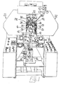
- the illustrative machine which is generally similar, except as hereinafter described, to the machine described in our co-pending European Patent Application No.32304472.2 is a machine for use in the combined lasting of heel seat and side portions of shoes and comprises a shoe support generally designated 10, including a last pin 12 on which a shoe can be supported, bottom uppermost, and a toe rest 14, a heel band 16, a heel seat wiper assembly including two wiper plates 18 (the heel band wiper plates constituting heel seat lasting instrumentalities of the machine), a holddown generally designated 20 and side lasting instrumentalities generally designated 22, said instrumentalities comprising a plurality of fingers 24, a plurality of clamp pads 26 and lasting strap elements 28 extending over said fingers 24 and pads 26.
- the side lasting instrumentalities 22 are generally similar to those described in our co-pending European Patent Application No. 81304527.5.
- the heel seat lasting instrumentalities also comprises fastener-inserting means generally designated 30, including individual devices actuated by a pneumatically operated striker plate 32.
- the shoe support 10 comprises a column 42, on which the last pin 12 and toe rest arrangement 14 are supported, the column 42 being mounted for sliding heightwise movement in a post 44 which is in turn mounted for pivotal movement, in a bracket 36, about a shaft (not shown) extending widthwise of the machine.
- first power means constituted by a piston-and-cylinder arrangement 46, is provided, a piston rod 48 of which is pivotally connected to the post 44.
- a shoe is placed on the shoe support and the shoe support is then caused to swing in the bracket 36 to bring the backpart of the shoe into engagement with the heel band 16, thereby positioning the shoe, in a direction extending along its length, in a desired relationship with the heel seat lasting instrumentalities of the machine.
- the illustrative machine also comprises second power means for moving the shoe support 10 heightwise to bring the heel seat region of the shoe supported thereby into engagement with the holddown 20, said second power means comprising a wedge member (not shown) movable along a horizontal path, on a base of the machine frame, by means of a piston-and-cylinder arrangement (not shown) supported by a bracket on said base, the wedge member being arranged to engage a foot (not shown) pivotally connected to the lower end of the column 42, said column extending through the post 44 and projecting downwardly from the under-side thereof.
- the foot, wedge member and piston-and-cylinder arrangement referred to above are denoted by reference numerals 74, 76, 78 respectively in our co-pending Application No.
- the heel band 16 of the illustrative machine, and the actuating means therefor are generally similar to the heel band actuating means of the machine described in our co-pending U.K. Patent Application No. 8020133 ( Publication No. 2052950).
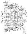
- the heel band is supported by an arrangement comprising a support plate 122 having bolted thereto a plate 124 having a cut-away portion forming a recess 126 for receiving a tab 128 forming part of a support bracket 130 to which the heel band is secured at the backseam region thereof.
- the heel band 16 Adjacent the backseam region, furthermore, are two lugs 134, welded to the plate 124 and a further plate 132, against which lugs the heel band can abut to provide additional support adjacent the backseam region thereof.
- the heel band 16 is generally U-shaped and the "legs" of the band are supported, and also actuated, each by a presser plate 138 which receives a stud 136 of the band in an open-ended slot and further which is pivotally supported on a lever 144.
- the levers 144 are pivotally supported, on spacer shafts 142 between the plates 124, 132, each spacer shaft supporting a further lever 146 which carries a roll 152 engageable with an inclined face provided by a wedge member 154.
- each wedge member 154 is mounted for sliding movement, widthwise of the machine, on a rod 156 secured centrally in a block 158 carried by the support plate 122, each wedge member 154 having a rearwardly extending lug 160.
- a cylinder 162 of a double-acting piston-and-cylinder arrangement is connected to one of said lugs 160 and a piston rod 164 of said arrangement to the other lug.
- each lever 146 carries an adjustable stop member 148 arranged to engage with the portion of its associated lever 144, a spring 150 being provided for urging the lever 144 against the stop member.
- actuation of the piston-and-cylinder arrangement 162, 164 causes the wedge members 154 to move towards one another and thus, through the rolls 152 and levers 146, to cause the levers 144 to pivot to urge the "legs" of the heel band 16 clampingly to engage the shoe.
- the support plate 122 is carried in slideways 100 provided on the main frame of the machine.
- a threaded shaft 114 is provided, held captive in a block 118 secured to the under-side of the block 158.
- a forward end of the threaded shaft 114 carries a knob 102 by which the operator can thus rotate the shaft, and the rearward end of the shaft is threadedly received in a further block 116 which is carried on the main frame.
- rotation of the shaft 114 is effective to vary the position of the support plate 122, and thus of the heel band 16, fore-and-aft of the machine.
- the heel band 16 of the illustrative machine is further mounted for movement between an operative position (as shown in Figure 2) and a retracted position, for which purpose the support plate 122 is movable in the slideways 100 in a manner now to be described.
- the block 116 is carried on two shaft 120 projecting.forwardly from the machine frame, the shaft being arranged one at either side of the shaft 114 and each shaft 120 having at its forward end a headed portion 121 against which a forward face of the block 116 can abut.
- the stop faces of the headed portions determine the operative position of the heel band 16.
- two springs 166 which are effective to urge the support plate 122, and the heel band 16.therewith, rearwardly out of said operative position to a retracted position.
- two wedge members 168 are provided arranged to act between a rearward face of the block 116 and a forward face of the part of the machine frame supporting the shafts 120, the wedge members 168 being movable heightwise under the action of pneumatic piston-and-cylinder arrangements 170.
- the piston-and-cylinder arrangements 170 are actuated and force the block 116, and thus the heel band 16 therewith, forwardly.
- the piston-and-cylinder arrangement 170 are actuated to withdraw the wedge members 168, whereupon the springs 166 operate to retract the support plate 122, and thus the heel band.
- the illustrative machine further comprises means for applying an updrafting force to the shoe upper in the heel breast line region thereof, said means comprising two grippers 172, arranged one at either side of the shoe support 10 adjacent the rearward end of the side lasting instrumentalities 22.
- Each gripper 172 is movable, by means of a piston-and-cylinder arrangement (not shown) between an advanced position, in which the gripper can engage and grip the upstanding lasting marginal portion of a shoe upper on the shoe support, in the heel breast line region thereof, and an out-of-the-way position, the arrangement being such that, in the operation of the machine, the grippers move to their advanced positions, grip said lasting marginal poritions and are retracted, thus to apply the updrafting force to the upper in said region. Subsequently, the grippers 172 release the upper, whereupon they are returned to their out-of-the-way positions.
- the operator places a shoe, comprising a shoe upper on a last with an insole on the last bottom, on the shoe support 10, locating the toe rest 14 appropriately according to whether the shoe is a left or a right, in conventional manner, and thereafter initiates a cycle of operation of the machine, in which firstly, by the operation of the piston-and-cylinder arrangement 46 the shoe support is swung rearwardly to carry the backpart of the shoe into the heel band 16, and also the piston-and-cylinder arrangement (not shown) operating the wedge member for the shoe support is operated to raise the shoe support to bring the heel seat region of the shoe supported thereon into engagement with the holddown 20 (as fully described in our Application No. 82304472.2, whereby the shoe is located both lengthwise and heightwise in relation to the heel seat wiper assembly 18 of the illustrative machine ( Figure 3a).
- the piston-and-cylinder arrangement 46 With the shoe clampingly urged by the wedge member (not shown) against the holddown 20, the piston-and-cylinder arrangement 46 is de-actuated and at the same time the wedge members 168, acting between the block 116 and the main frame for maintaining the heel band 16 in its operative position, are retracted by the piston-and-cylinder arrangement 170..Thus, the pressure applied by the heel band in and adjacent the backseam region of the shoe upper is relieved and further the backseam region of the upper and the heel band are separated from one another so that, during the subsequent side lasting operation the backpart of the upper is free of any clamping pressure at least in and adjacent the backseam region thereof.
- the breast line grippers 172 are then moved to their advanced position and caused to grip the upstanding lasting margin of the shoe upper in the heel breast line thereof (see Figure 3b).
- the breast line grippers 172 are then caused to move towards their out-of-the-way position, whereby an updrafting force is applied thereto in said region.
- the "legs" of the heel band 16 are caused to close on to the shoe upper, by the action of piston-and-cylinder arrangement 162, 164, thus to clamp the upper against the last in the heel breast line region, so that the upper material displaced by the action of the breast line grippers 172 can be maintained in the position to which it has been thus displaced.
- the breast line grippers 172 can be caused to release their grip on the lasting marginal portions of the upper and retract to their out-of-the-way position, and then cement is applied progressively along the opposite marginal portions of the insole by means of nozzles 180 ( Figure 1), as more fully described in our co-pending U.K. Patent Application No.7914851. (Publication No. 2047577)
- the side lasting instrumentalities 22 are moved inwardly firstly to clamp the side portions of the shoe upper against the last, and thereafter to cause the lasting marginal portions of the side portions to be wiped over and pressed against corresponding marginal portions of the insole, previously applied adhesive serving to cause said marginal portions to be bonded together.
- the side lasting instrumentalities then dwell in pressing engagement with the shoe bottom to enable the bond to be consolidated (see Figure 3c).
- the heel seat wiper assembly 18 is caused to move inwardly from a retracted position and lasting marginal portions of the heel seat portion of the upper are thus wiped over and pressed against corresponding marginal portions of the insole, tacks then being inserted by the fastener-inserting means to secure the over-wiped lasting marginal portions to the corresponding marginal portions of the insole (see Figure 3d).
- the shoe upper is thus lasted from the joint region to the heel end by the side lasting and heel seat lasting instrumentalities, which together provide a continuous wiping surface over the whole region to be lasted. Furthermore, because, during the side lasting operation, the heel band is not exerting any toeward force on the upper, the side lasting operation can be effected without excess material being present in the heel breast line region, whereafter the heel seat lasting operation can take place, such operation itself taking up any excess material which may be found in the heel seat region.
Landscapes
- Footwear And Its Accessory, Manufacturing Method And Apparatuses (AREA)
Applications Claiming Priority (2)
| Application Number | Priority Date | Filing Date | Title |
|---|---|---|---|
| GB8132558 | 1981-10-29 | ||
| GB8132558 | 1981-10-29 |
Publications (2)
| Publication Number | Publication Date |
|---|---|
| EP0078622A2 true EP0078622A2 (de) | 1983-05-11 |
| EP0078622A3 EP0078622A3 (de) | 1985-12-11 |
Family
ID=10525464
Family Applications (1)
| Application Number | Title | Priority Date | Filing Date |
|---|---|---|---|
| EP82305513A Withdrawn EP0078622A3 (de) | 1981-10-29 | 1982-10-18 | Dauerhafte Fersen- und Seitenteile eines Schuhs |
Country Status (3)
| Country | Link |
|---|---|
| US (1) | US4593423A (de) |
| EP (1) | EP0078622A3 (de) |
| CA (1) | CA1197356A (de) |
Cited By (1)
| Publication number | Priority date | Publication date | Assignee | Title |
|---|---|---|---|---|
| EP0241300A3 (de) * | 1986-04-11 | 1989-07-12 | International Shoe Machine Corporation | Maschine zum Zwicken von Schuhen im Seiten- und Fersenbereich |
Families Citing this family (2)
| Publication number | Priority date | Publication date | Assignee | Title |
|---|---|---|---|---|
| GB8805135D0 (en) * | 1988-03-03 | 1988-03-30 | British United Shoe Machinery | Machine for lasting side portions of shoes |
| GB9109271D0 (en) * | 1991-04-30 | 1991-06-19 | British United Shoe Machinery | Shoe support and machine for use in the manufacture of shoes |
Family Cites Families (5)
| Publication number | Priority date | Publication date | Assignee | Title |
|---|---|---|---|---|
| US28825A (en) * | 1860-06-26 | Improved iron tie for cotton-bales | ||
| USRE28825E (en) | 1966-02-18 | 1976-05-25 | Lisbeth N. Godley | Method and apparatus for use in lasting shoes |
| US3934294A (en) * | 1974-12-09 | 1976-01-27 | International Shoe Machine Corporation | Lasting machine and method |
| US4082060A (en) * | 1977-01-26 | 1978-04-04 | International Shoe Machine Corporation | Cement side and heel lasting machine |
| GB2047072B (en) * | 1979-04-21 | 1983-02-02 | British United Shoe Machinery | Shank lasting wipers |
-
1982
- 1982-10-18 EP EP82305513A patent/EP0078622A3/de not_active Withdrawn
- 1982-10-25 US US06/436,290 patent/US4593423A/en not_active Expired - Fee Related
- 1982-10-28 CA CA000414350A patent/CA1197356A/en not_active Expired
Cited By (1)
| Publication number | Priority date | Publication date | Assignee | Title |
|---|---|---|---|---|
| EP0241300A3 (de) * | 1986-04-11 | 1989-07-12 | International Shoe Machine Corporation | Maschine zum Zwicken von Schuhen im Seiten- und Fersenbereich |
Also Published As
| Publication number | Publication date |
|---|---|
| US4593423A (en) | 1986-06-10 |
| CA1197356A (en) | 1985-12-03 |
| EP0078622A3 (de) | 1985-12-11 |
Similar Documents
| Publication | Publication Date | Title |
|---|---|---|
| US4593423A (en) | Lasting heel seat and side portions of a shoe | |
| EP0100636B1 (de) | Zwickmaschine für den Zehenbereich mit einstellbarer Fersenhalterung | |
| US4095302A (en) | Manufacture of shoes | |
| US4400839A (en) | Machine for lasting heel seat portions of shoes | |
| US4924546A (en) | Method of and apparatus for pulling over and lasting footwear | |
| CA1036760A (en) | Wiping method and lasting machine-shoe assembly combination used therewith | |
| US4407033A (en) | Combination toe and side lasting machine | |
| US2024175A (en) | Method and means for use in making shoes | |
| US2727257A (en) | Machine for operating on shoes | |
| US2505134A (en) | Lasting machine | |
| GB2126870A (en) | Side lasting machines | |
| US4744120A (en) | Shoe support for shoe upper conforming machine | |
| US3115649A (en) | Heel clamp | |
| US1977913A (en) | Manufacture of shoes | |
| US1168011A (en) | Machine for working an upper on a list. | |
| US3691575A (en) | Toe wiping with insole unsecured to last bottom | |
| USRE26700E (en) | Method op lasting a shoe | |
| US2041955A (en) | Machine for shaping uppers overe lasts | |
| US2157123A (en) | Shoe bottom pressing machine | |
| US2181896A (en) | Machine for shaping uppers over lasts | |
| US3075209A (en) | Machines for attaching loose outsoles to the breasts of loose louis heels | |
| US2722022A (en) | Cement lasting machines | |
| US4377876A (en) | Shoe lasting machine | |
| US2287275A (en) | Trimming machine | |
| US2385482A (en) | Heel breasting machine |
Legal Events
| Date | Code | Title | Description |
|---|---|---|---|
| PUAI | Public reference made under article 153(3) epc to a published international application that has entered the european phase |
Free format text: ORIGINAL CODE: 0009012 |
|
| AK | Designated contracting states |
Designated state(s): DE FR GB IT |
|
| PUAL | Search report despatched |
Free format text: ORIGINAL CODE: 0009013 |
|
| AK | Designated contracting states |
Designated state(s): DE FR GB IT |
|
| STAA | Information on the status of an ep patent application or granted ep patent |
Free format text: STATUS: THE APPLICATION IS DEEMED TO BE WITHDRAWN |
|
| 18D | Application deemed to be withdrawn |
Effective date: 19860812 |
|
| RIN1 | Information on inventor provided before grant (corrected) |
Inventor name: FLANDERS, JAMES ROBERT Inventor name: PRICE, FRANK CHRISTOPHER Inventor name: CLACKSON, ANDREW PETER |