EP0078652A1 - Appareil pour la pulvérisation d'un liquide - Google Patents
Appareil pour la pulvérisation d'un liquide Download PDFInfo
- Publication number
- EP0078652A1 EP0078652A1 EP82305669A EP82305669A EP0078652A1 EP 0078652 A1 EP0078652 A1 EP 0078652A1 EP 82305669 A EP82305669 A EP 82305669A EP 82305669 A EP82305669 A EP 82305669A EP 0078652 A1 EP0078652 A1 EP 0078652A1
- Authority
- EP
- European Patent Office
- Prior art keywords
- liquid
- disc
- spray apparatus
- liquid spray
- splines
- Prior art date
- Legal status (The legal status is an assumption and is not a legal conclusion. Google has not performed a legal analysis and makes no representation as to the accuracy of the status listed.)
- Ceased
Links
Images


Classifications
-
- B—PERFORMING OPERATIONS; TRANSPORTING
- B05—SPRAYING OR ATOMISING IN GENERAL; APPLYING FLUENT MATERIALS TO SURFACES, IN GENERAL
- B05B—SPRAYING APPARATUS; ATOMISING APPARATUS; NOZZLES
- B05B1/00—Nozzles, spray heads or other outlets, with or without auxiliary devices such as valves, heating means
- B05B1/34—Nozzles, spray heads or other outlets, with or without auxiliary devices such as valves, heating means designed to influence the nature of flow of the liquid or other fluent material, e.g. to produce swirl
- B05B1/3405—Nozzles, spray heads or other outlets, with or without auxiliary devices such as valves, heating means designed to influence the nature of flow of the liquid or other fluent material, e.g. to produce swirl to produce swirl
- B05B1/341—Nozzles, spray heads or other outlets, with or without auxiliary devices such as valves, heating means designed to influence the nature of flow of the liquid or other fluent material, e.g. to produce swirl to produce swirl before discharging the liquid or other fluent material, e.g. in a swirl chamber upstream the spray outlet
- B05B1/3421—Nozzles, spray heads or other outlets, with or without auxiliary devices such as valves, heating means designed to influence the nature of flow of the liquid or other fluent material, e.g. to produce swirl to produce swirl before discharging the liquid or other fluent material, e.g. in a swirl chamber upstream the spray outlet with channels emerging substantially tangentially in the swirl chamber
- B05B1/3463—Nozzles, spray heads or other outlets, with or without auxiliary devices such as valves, heating means designed to influence the nature of flow of the liquid or other fluent material, e.g. to produce swirl to produce swirl before discharging the liquid or other fluent material, e.g. in a swirl chamber upstream the spray outlet with channels emerging substantially tangentially in the swirl chamber the channels extending outwardly, e.g. radially from the inside to the outside
-
- B—PERFORMING OPERATIONS; TRANSPORTING
- B05—SPRAYING OR ATOMISING IN GENERAL; APPLYING FLUENT MATERIALS TO SURFACES, IN GENERAL
- B05B—SPRAYING APPARATUS; ATOMISING APPARATUS; NOZZLES
- B05B1/00—Nozzles, spray heads or other outlets, with or without auxiliary devices such as valves, heating means
- B05B1/26—Nozzles, spray heads or other outlets, with or without auxiliary devices such as valves, heating means with means for mechanically breaking-up or deflecting the jet after discharge, e.g. with fixed deflectors; Breaking-up the discharged liquid or other fluent material by impinging jets
- B05B1/262—Nozzles, spray heads or other outlets, with or without auxiliary devices such as valves, heating means with means for mechanically breaking-up or deflecting the jet after discharge, e.g. with fixed deflectors; Breaking-up the discharged liquid or other fluent material by impinging jets with fixed deflectors
- B05B1/265—Nozzles, spray heads or other outlets, with or without auxiliary devices such as valves, heating means with means for mechanically breaking-up or deflecting the jet after discharge, e.g. with fixed deflectors; Breaking-up the discharged liquid or other fluent material by impinging jets with fixed deflectors the liquid or other fluent material being symmetrically deflected about the axis of the nozzle
-
- B—PERFORMING OPERATIONS; TRANSPORTING
- B05—SPRAYING OR ATOMISING IN GENERAL; APPLYING FLUENT MATERIALS TO SURFACES, IN GENERAL
- B05B—SPRAYING APPARATUS; ATOMISING APPARATUS; NOZZLES
- B05B1/00—Nozzles, spray heads or other outlets, with or without auxiliary devices such as valves, heating means
- B05B1/34—Nozzles, spray heads or other outlets, with or without auxiliary devices such as valves, heating means designed to influence the nature of flow of the liquid or other fluent material, e.g. to produce swirl
- B05B1/3405—Nozzles, spray heads or other outlets, with or without auxiliary devices such as valves, heating means designed to influence the nature of flow of the liquid or other fluent material, e.g. to produce swirl to produce swirl
- B05B1/341—Nozzles, spray heads or other outlets, with or without auxiliary devices such as valves, heating means designed to influence the nature of flow of the liquid or other fluent material, e.g. to produce swirl to produce swirl before discharging the liquid or other fluent material, e.g. in a swirl chamber upstream the spray outlet
- B05B1/3421—Nozzles, spray heads or other outlets, with or without auxiliary devices such as valves, heating means designed to influence the nature of flow of the liquid or other fluent material, e.g. to produce swirl to produce swirl before discharging the liquid or other fluent material, e.g. in a swirl chamber upstream the spray outlet with channels emerging substantially tangentially in the swirl chamber
- B05B1/3431—Nozzles, spray heads or other outlets, with or without auxiliary devices such as valves, heating means designed to influence the nature of flow of the liquid or other fluent material, e.g. to produce swirl to produce swirl before discharging the liquid or other fluent material, e.g. in a swirl chamber upstream the spray outlet with channels emerging substantially tangentially in the swirl chamber the channels being formed at the interface of cooperating elements, e.g. by means of grooves
- B05B1/3442—Nozzles, spray heads or other outlets, with or without auxiliary devices such as valves, heating means designed to influence the nature of flow of the liquid or other fluent material, e.g. to produce swirl to produce swirl before discharging the liquid or other fluent material, e.g. in a swirl chamber upstream the spray outlet with channels emerging substantially tangentially in the swirl chamber the channels being formed at the interface of cooperating elements, e.g. by means of grooves the interface being a cone having the same axis as the outlet
-
- B—PERFORMING OPERATIONS; TRANSPORTING
- B05—SPRAYING OR ATOMISING IN GENERAL; APPLYING FLUENT MATERIALS TO SURFACES, IN GENERAL
- B05B—SPRAYING APPARATUS; ATOMISING APPARATUS; NOZZLES
- B05B3/00—Spraying or sprinkling apparatus with moving outlet elements or moving deflecting elements
- B05B3/02—Spraying or sprinkling apparatus with moving outlet elements or moving deflecting elements with rotating elements
- B05B3/04—Spraying or sprinkling apparatus with moving outlet elements or moving deflecting elements with rotating elements driven by the liquid or other fluent material discharged, e.g. the liquid actuating a motor before passing to the outlet
- B05B3/0417—Spraying or sprinkling apparatus with moving outlet elements or moving deflecting elements with rotating elements driven by the liquid or other fluent material discharged, e.g. the liquid actuating a motor before passing to the outlet comprising a liquid driven rotor, e.g. a turbine
- B05B3/0429—Spraying or sprinkling apparatus with moving outlet elements or moving deflecting elements with rotating elements driven by the liquid or other fluent material discharged, e.g. the liquid actuating a motor before passing to the outlet comprising a liquid driven rotor, e.g. a turbine the rotating outlet elements being directly attached to the rotor or being an integral part thereof
-
- B—PERFORMING OPERATIONS; TRANSPORTING
- B05—SPRAYING OR ATOMISING IN GENERAL; APPLYING FLUENT MATERIALS TO SURFACES, IN GENERAL
- B05B—SPRAYING APPARATUS; ATOMISING APPARATUS; NOZZLES
- B05B5/00—Electrostatic spraying apparatus; Spraying apparatus with means for charging the spray electrically; Apparatus for spraying liquids or other fluent materials by other electric means
- B05B5/025—Discharge apparatus, e.g. electrostatic spray guns
- B05B5/04—Discharge apparatus, e.g. electrostatic spray guns characterised by having rotary outlet or deflecting elements, i.e. spraying being also effected by centrifugal forces
- B05B5/0403—Discharge apparatus, e.g. electrostatic spray guns characterised by having rotary outlet or deflecting elements, i.e. spraying being also effected by centrifugal forces characterised by the rotating member
Definitions
- This invention relates to liquid spray apparatus and particularly but not exclusively to liquid spray apparatus for use in an electrostatic liquid spraying apparatus.
- An electrostatic liquid spraying apparatus usually comprises a conducting surface on to which the liquid spray impinges and an earthed field intensifying electrode mounted adjacent to the conductive surface.
- the conducting surface is electrically charged to a potential of the order of 1-20 kilovolts the electrostatic field at the surface causes the liquid spray droplets to atomize and form electrically charged particles which are projected away from the field intensifying electrode.
- liquid spray apparatus comprises a liquid supply duct, a surface at one end of the duct on to which the liquid is adapted to impringe, a nozzle for distributing the liquid after it has passed over the surface, means for imparting a swirling motion to the liquid and means for varying the flow rate of liquid through the liquid spray apparatus.
- a cover member is located adjacent to the surface to form a nozzle between it and the surface.
- the surface comprises a circular disc with a central axis, the liquid supply duct leading to a central portion of the disc.
- the disc may be provided with a plurality of channels extending from the central portion of the disc to the periphery of the disc, the longitudinal axis of each channel being shaped to form a small acute angle with the periphery of the disc whereby a swirl is imparted to the liquid when it leaves the periphery of the disc.
- the axes of the channels extend from the central portion of the disc and meet the periphery of the disc at a point with an extremely small acute angle to a tangent to the periphery at that point or meet the periphery of the disc substantially tangentially thereto.
- each channel may take the form of a lemniscate.
- the cover member is shaped to form an annular gap between the periphery of the disc and the edge of the cover member forming an annular nozzle.
- the means for varying the flow rate of liquid through the liquid spray apparatus may comprise valve means provided on the central portion of the disc to permit liquid to enter a predetermined number of the channels only and to prevent liquid from entering any of the channels.
- the valve means may comprise a plate having a plurality of orifices, rotation of the plate relative to the disc aligning one or more orifices with the one or more ends of the channels.
- the liquid supply duct may include a plurality of helical channels to impart a swirl to the liquid, the valve means being located upstream of the helical channels.
- the means for varying the flow rate of liquid through the liquid spray apparatus may comprise first and second splined members located within a. hollow portion of the liquid supply duct, the second splined member abutting the end of the first splined member, the outer ends of the splines of each splined member cooperating with the walls of the duct so that the liquid is constrained to flow along the spaces between the splines, the first and second splined members being relatively rotatable such that the splines on the first and second members can be moved in and out of alignment whereby the rate of flow of liquid through the spaces is varied.
- the cross-sectional shape of the splines may be the same on each splined member such that the flow of liquid can be varied from a minimum to a maximum amount or the cross-sectional shape of the splines on one of the splined members may be the same as the cross-sectional shape of the spaces between the splines on the other splined member whereby the flow of liquid can be prevented.
- Suitable means are preferably provided for relatively moving the splined members externally of the duct.
- the liquid spray apparatus shown in Figure 1 comprises a hollow liquid supply tube 10 which is secured to a conical cover 12.
- a conical disc 14 having a shaft 16 extending from a central flat portion 18 of the disc is supported inside the cover 12 by bearings 20 and 22 in which the shaft 16 is supported.
- the cover 12 is in intimate contact with the conical surface of the disc 14 and is provided at its lower end with a circular flange 24.
- the flange 24 is spaced from the periphery of the disc to produce an annular gap 26 therebetween.
- each channel 28 In the conical surface of the disc 14 are formed three channels 28, each having a lemniscate or snail shape and extending from the central flat portion 18 to the periphery of the disc.
- the longitudinal axis 32 of each channel 28 initially extends radially outwardly from the flat portion 18 and curves to meet the periphery of the disc at a point substantially tangentially or at a very small acute angle a to a tangent 30 to the periphery at that point.
- a valve which is adapted to block the ends 32, 34 and 36 of one, two or all three of the channels 28 and hence vary the flow rate of liquid through the spraying apparatus between a maximum value and zero.
- the valve comprises a plate 38 which is secured inside the tube 10 and the disc 14 is rotatable relative to the plate 38 through four different positions. Rotation of the disc 14 is achieved manually and the disc can be located in any of its four different positions by means not shown.
- FIGS 3 to 6 show the plate 14 which includes the three ends 32, 34 and 36 of the channels 28.
- the plate 38 has six slots 40, 42, 44, 46, 48 and 50 each corresponding to the shape of the ends 32, 34 and 36, and these slots are positioned so that in the first position ( Figure 3) the plate 38 covers all the ends 32, 34 and 36. In its second position ( Figure 4) the plate 38 has been rotated in an anti-clockwise direction relative to the disc 14 and the slot 40 is aligned with the end 32, the ends 34 and 36 remaining covered.
- the plate 38 In the third position ( Figure 5) the plate 38 is further rotated in an anti-clockwise direction relative to the disc 14, and the slot 42 is aligned with the end 32, the slot 46 is aligned with the end 34 and the end 36 is covered. Further anti-clockwise rotation of the plate 38 relative to the disc 14 into the fourth position ( Figure 6) aligns the slot 14 with the end 32, the slot 48 with the end 34 and the slot 50 with the end 36.
- the disc 14 can thus be adjusted so that all, two, one or none of three of the ends 32, 34 and 36 are covered to vary the flow of liquid from zero to a maximum value respectively.
- a liquid to be sprayed is supplied down the tube 10 and through the slots in the plate 38 which are aligned with the ends 32, 34 and 36 of the channels 28.
- the liquid flows down the relevant channels 28, being retained in the channels by the proximity of the cover 12 to the conical portion of the disc 14, and exits substantially tangentially from the ends of the channels 28 into the annular gap 26.
- An annular spray thus emanates from the gap 26 depending on the rate of flow of liquid or a pressure supply of air which may also be supplied down the tube 10.
- the spray apparatus is particularly suitable for use in an electrostatic spraying system.
- the disc 14 can be made of a conducting material and electrically charged to a potential of 1 to 20 kilovolts whilst an earthed field intensifying electrode can be formed around the outside of the cover 12 or be formed in the cover 12 if the cover is made of an insulating material.
- the spray droplets are atomised when they hit the surface of the disc 14 and atomisation is achieved to a high order by the combination of inertial and electrostatic forces.
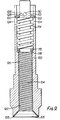
- the liquid spray apparatus shown in Figure 7 comprises a hollow liquid supply tube 70 which is secured to a conical cover 72.
- a conical disc 74 is supported inside the cover 72 by a splined shaft 76 which is itself supported by a further splined shaft 78 which is rigidly supported inside the tube 70.
- the cover 72 is located very close to the conical surface of the disc 74 and is provided at its lower end with a circular flange 84.
- the flange 84 is spaced from the periphery of the disc to produce an annular gap 86 therebetween.
- the splined shaft 76 is rotatable relative to the further splined shaft 78 and the splines 88 and 86 on the shafts 78 and 76 respectively are shown in Figure 8a.
- the splines 88 are substantially triangular in section and thus leave a number of substantially triangular passages between the shaft 78 and the wall of the tube 70.
- the splines 86 on the shaft 76 are similar in shape and have similar passages therebetween, and liquid when supplied down the tube 70 passes down the passages between the shaft 78 and the tube 70.
- Figure 8b illustrates an alternative shape for the splines of shaft 78 and the splines of the shaft 76.
- the splines 90 on the shaft 78 are substantially square-shaped and the splines 92 of the shaft 76 are of similar cross-sectional shape to the passages between the splines 90.
- the shaft 76 may be rotated by rotating the disc-74 inside the cover 72, suitable means being provided for locking the disc 74 in a predetermined position.
- the liquid spray apparatus illustrated in Figure 9 comprises a hollow liquid supply tube 100 the lower end of its internal surface being formed into a conical flare 102. Inside the tube 100 is located a shaft 104 which extends through the entire length of the tube 100 and which has a conical flared surface 106 formed at its lower end. The surface 106 is spaced from the flared surface 102 of the tube 100 by suitable projections or ribs (not shown). The annular gap thus formed defines a spray nozzle 108.
- the shaft 104 is held in position in the tube 100 by a pin 110 which extends through the shaft 104 and abuts a spring urged washer 112, the compression spring 114 therefore urging the shaft 104 upwards in the tube 100 and maintaining the nozzle 108 at the correct size.
- the lower end of the spring 114 abuts a plate 116 which itself abuts a shoulder 118 formed inside the tube 100.
- the shaft 100, below the position of the shoulder 118 is provided with a plurality of helical grooves on its outer surface which co-operate with the internal wall of the tube 100 to form helical passages 120.
- the plate 116 is formed as the plate 38 in Figures 3, 4, 5 and 6 to block the upper ends of one, two or all three of the passages 120 and hence vary the flow rate of liquid through the spraying apparatus between a maximum value and zero.
- the tube 100 is rotatable on the shaft 104 whilst the plate 116 is secured to the tube 100 and the washer 112 is prevented from rotation inside the tube by side members 122 which engage longitudinally extending slots 124 formed at the upper end of the tube 100.
- the washer 122 is provided with alternate projections 126 and depressions 128 arranged circumferentially on its surface so that as the tube 100 rotates the pin 110 rides over the projections 126 and enters the next depressions. 128
- the washer 12 comprises the spring 114 as this happens and thus the position of the plate 116 relative to the helical passages 120 can be adjusted and hence the rate of flow of liquid can be varied.
- the helical passages 120 cause the liquid to swirl before it hits the conical surface 106 from which the liquid leaves the apparatus through the nozzle 108.
Landscapes
- Electrostatic Spraying Apparatus (AREA)
- Nozzles (AREA)
Applications Claiming Priority (4)
| Application Number | Priority Date | Filing Date | Title |
|---|---|---|---|
| GB8133077 | 1981-11-03 | ||
| GB8133077 | 1981-11-03 | ||
| GB8134383 | 1981-11-14 | ||
| GB8134383 | 1981-11-14 |
Publications (1)
| Publication Number | Publication Date |
|---|---|
| EP0078652A1 true EP0078652A1 (fr) | 1983-05-11 |
Family
ID=26281147
Family Applications (1)
| Application Number | Title | Priority Date | Filing Date |
|---|---|---|---|
| EP82305669A Ceased EP0078652A1 (fr) | 1981-11-03 | 1982-10-26 | Appareil pour la pulvérisation d'un liquide |
Country Status (3)
| Country | Link |
|---|---|
| US (1) | US4515314A (fr) |
| EP (1) | EP0078652A1 (fr) |
| GB (1) | GB2108869B (fr) |
Cited By (2)
| Publication number | Priority date | Publication date | Assignee | Title |
|---|---|---|---|---|
| CN102292527A (zh) * | 2008-12-22 | 2011-12-21 | 伊顿公司 | 喇叭形喷嘴 |
| EP3053654A1 (fr) * | 2015-02-03 | 2016-08-10 | Xiamen Solex High-tech Industries Co., Ltd. | Dispositif de sortie avec fonction de rideau d'eau creux |
Families Citing this family (11)
| Publication number | Priority date | Publication date | Assignee | Title |
|---|---|---|---|---|
| US4660772A (en) * | 1984-09-26 | 1987-04-28 | A. O. Smith Corporation | Electrostatic powder spray gun nozzle |
| US4986475A (en) * | 1988-02-19 | 1991-01-22 | Nabisco Brands, Inc. | Method and apparatus for spraying fluids |
| DE4106140C2 (de) * | 1991-02-27 | 1994-11-24 | Escher Wyss Gmbh | Vorrichtung und deren Anwendung zur Entlüftung einer Papierstoffsuspension |
| US20050001065A1 (en) * | 2001-08-01 | 2005-01-06 | Kidde-Fenwal, Inc. | Nozzle apparatus and method for atomizing fluids |
| GB2428208A (en) * | 2005-07-13 | 2007-01-24 | Geoffrey Norman Sloan | Cleaning nozzle arrangement |
| US8074901B2 (en) * | 2005-12-01 | 2011-12-13 | Uniwave, Inc. | Lubricator nozzle and emitter element |
| US20120168538A1 (en) * | 2009-10-16 | 2012-07-05 | Tiefu Han | Spin Annular Slit Spray Nozzle and Spray Apparatus Thereof |
| US20130081658A1 (en) * | 2011-09-30 | 2013-04-04 | Semes Co., Ltd. | Apparatus and method for treating substrate |
| WO2016183657A1 (fr) * | 2015-05-19 | 2016-11-24 | Exterran Water Solutions Ulc | Buse de lavage de filtre à contre-courant |
| US9943784B2 (en) | 2015-05-21 | 2018-04-17 | Exterran Water Solutions Ulc | Filter backwash nozzle |
| CN116492583A (zh) * | 2023-05-06 | 2023-07-28 | 中国人民解放军西部战区总医院 | 一种腿部药液均匀喷涂装置及其喷涂方法 |
Citations (5)
| Publication number | Priority date | Publication date | Assignee | Title |
|---|---|---|---|---|
| DE466932C (de) * | 1928-11-06 | Joh Weinlich | Duese fuer Farbzerstaeuber | |
| AT186761B (de) * | 1952-09-29 | 1956-09-10 | August Harder | Spritzkopf für Spritzpistolen |
| GB1518547A (en) * | 1974-10-16 | 1978-07-19 | Ransburg Ja Ltd | Coating apparatus |
| GB2020200A (en) * | 1978-03-08 | 1979-11-14 | Air Ind | Electrostatic spraying |
| US4221339A (en) * | 1977-12-03 | 1980-09-09 | Nakaya Sangyo Kabushiki Kaisha | Liquid spraying device |
Family Cites Families (9)
| Publication number | Priority date | Publication date | Assignee | Title |
|---|---|---|---|---|
| US1435778A (en) * | 1921-12-21 | 1922-11-14 | Joseph A Williams | Oil burner |
| BE417492A (fr) * | 1935-10-17 | |||
| US2131936A (en) * | 1936-04-07 | 1938-10-04 | Genovese Pietro Del | Control device for atomizer nozzles, burner heads, and the like |
| NL41451C (fr) * | 1937-01-04 | 1937-09-15 | ||
| GB555736A (en) * | 1942-03-02 | 1943-09-06 | Charles Francis Becker | Improvements in nozzles particularly fire hose nozzles |
| US2408196A (en) * | 1944-06-23 | 1946-09-24 | Rudolph E Carlson | Sprinkler head |
| GB752333A (en) * | 1952-11-13 | 1956-07-11 | Shell Refining & Marketing Co | Apparatus for mixing a liquid and a gas |
| GB797196A (en) * | 1955-02-28 | 1958-06-25 | Monroe Jordan Singer | Adjustable spray head assembly for buried sprinkler system |
| US3408006A (en) * | 1965-10-22 | 1968-10-29 | Swimquip Inc | Liquid jet producing device |
-
1982
- 1982-10-26 EP EP82305669A patent/EP0078652A1/fr not_active Ceased
- 1982-10-26 GB GB08230565A patent/GB2108869B/en not_active Expired
- 1982-11-01 US US06/438,388 patent/US4515314A/en not_active Expired - Fee Related
Patent Citations (5)
| Publication number | Priority date | Publication date | Assignee | Title |
|---|---|---|---|---|
| DE466932C (de) * | 1928-11-06 | Joh Weinlich | Duese fuer Farbzerstaeuber | |
| AT186761B (de) * | 1952-09-29 | 1956-09-10 | August Harder | Spritzkopf für Spritzpistolen |
| GB1518547A (en) * | 1974-10-16 | 1978-07-19 | Ransburg Ja Ltd | Coating apparatus |
| US4221339A (en) * | 1977-12-03 | 1980-09-09 | Nakaya Sangyo Kabushiki Kaisha | Liquid spraying device |
| GB2020200A (en) * | 1978-03-08 | 1979-11-14 | Air Ind | Electrostatic spraying |
Cited By (3)
| Publication number | Priority date | Publication date | Assignee | Title |
|---|---|---|---|---|
| CN102292527A (zh) * | 2008-12-22 | 2011-12-21 | 伊顿公司 | 喇叭形喷嘴 |
| EP3053654A1 (fr) * | 2015-02-03 | 2016-08-10 | Xiamen Solex High-tech Industries Co., Ltd. | Dispositif de sortie avec fonction de rideau d'eau creux |
| CN105983490A (zh) * | 2015-02-03 | 2016-10-05 | 厦门松霖科技有限公司 | 一种可形成中空水幕的出水装置 |
Also Published As
| Publication number | Publication date |
|---|---|
| GB2108869A (en) | 1983-05-25 |
| GB2108869B (en) | 1986-02-26 |
| US4515314A (en) | 1985-05-07 |
Similar Documents
| Publication | Publication Date | Title |
|---|---|---|
| US4515314A (en) | Liquid spray apparatus | |
| US5011086A (en) | Spray coating device for electrically conductive coating liquids | |
| EP0230341B1 (fr) | Buse de pulvérisation électrostatique | |
| US4087050A (en) | Swirl type pressure fuel atomizer | |
| EP0236794B1 (fr) | Appareil de pulvérisation électrostatique pour poudre de revêtement | |
| US5697553A (en) | Streaked spray nozzle for enhanced air/fuel mixing | |
| EP0140477B1 (fr) | Buse de turbulence d'air | |
| CA2041512A1 (fr) | Coupelle rotative | |
| US3421693A (en) | Pneumatic atomizer for spraying liquids | |
| EP0117472B1 (fr) | Pulvérisateur pour un brûleur à combustible liquide | |
| JPS61259774A (ja) | 調整可能な粉体スプレノズル | |
| GB2121320A (en) | An atomiser appliance for coating objects with powder | |
| US2396449A (en) | Spray nozzle | |
| US3221992A (en) | Coating material motive agent atomizer head | |
| US4365753A (en) | Boundary layer prefilmer airblast nozzle | |
| US7735756B2 (en) | Advanced mechanical atomization for oil burners | |
| DE3716776A1 (de) | Nicht-leitender rotierender zerstaeuber | |
| US2902223A (en) | Liquid atomizers | |
| US3595482A (en) | Spray devices | |
| DE2641605A1 (de) | Brennstoff-zerstaeuber mit zentralinjektion | |
| EP0395645A1 (fr) | Vaporisateur de rev tements electriquement conducteurs | |
| GB2118460A (en) | Liquid spray apparatus | |
| CN112797423A (zh) | 一种雾化喷嘴及废液焚烧装置 | |
| US3342418A (en) | Coating apparatus | |
| JP2001327896A (ja) | 2流体霧化スプレーノズル |
Legal Events
| Date | Code | Title | Description |
|---|---|---|---|
| PUAI | Public reference made under article 153(3) epc to a published international application that has entered the european phase |
Free format text: ORIGINAL CODE: 0009012 |
|
| AK | Designated contracting states |
Designated state(s): AT BE CH DE FR IT LI LU NL SE |
|
| 17P | Request for examination filed |
Effective date: 19830917 |
|
| STAA | Information on the status of an ep patent application or granted ep patent |
Free format text: STATUS: THE APPLICATION HAS BEEN REFUSED |
|
| 18R | Application refused |
Effective date: 19860120 |
|
| RIN1 | Information on inventor provided before grant (corrected) |
Inventor name: CURRALL, WILLIAM JAMES PETER |