EP0078706B1 - Echangeur de chaleur à lit fluidifié avec circulation induite utilisant une fluidification directionnelle et/ou différentielle - Google Patents
Echangeur de chaleur à lit fluidifié avec circulation induite utilisant une fluidification directionnelle et/ou différentielle Download PDFInfo
- Publication number
- EP0078706B1 EP0078706B1 EP82305824A EP82305824A EP0078706B1 EP 0078706 B1 EP0078706 B1 EP 0078706B1 EP 82305824 A EP82305824 A EP 82305824A EP 82305824 A EP82305824 A EP 82305824A EP 0078706 B1 EP0078706 B1 EP 0078706B1
- Authority
- EP
- European Patent Office
- Prior art keywords
- bed
- nozzles
- air
- heat exchanger
- plate
- Prior art date
- Legal status (The legal status is an assumption and is not a legal conclusion. Google has not performed a legal analysis and makes no representation as to the accuracy of the status listed.)
- Expired
Links
- 238000005243 fluidization Methods 0.000 title description 3
- 239000000463 material Substances 0.000 claims description 50
- 239000011236 particulate material Substances 0.000 claims description 32
- 238000007599 discharging Methods 0.000 claims description 10
- 239000000446 fuel Substances 0.000 description 12
- 239000002245 particle Substances 0.000 description 12
- 239000003245 coal Substances 0.000 description 10
- 238000002485 combustion reaction Methods 0.000 description 10
- 239000012530 fluid Substances 0.000 description 10
- 239000003463 adsorbent Substances 0.000 description 9
- 238000004891 communication Methods 0.000 description 8
- NINIDFKCEFEMDL-UHFFFAOYSA-N Sulfur Chemical compound [S] NINIDFKCEFEMDL-UHFFFAOYSA-N 0.000 description 5
- 230000005484 gravity Effects 0.000 description 5
- 229910052717 sulfur Inorganic materials 0.000 description 5
- 239000011593 sulfur Substances 0.000 description 5
- 239000007789 gas Substances 0.000 description 4
- 238000005192 partition Methods 0.000 description 4
- 239000002802 bituminous coal Substances 0.000 description 3
- 238000006243 chemical reaction Methods 0.000 description 3
- 230000007423 decrease Effects 0.000 description 3
- 239000000203 mixture Substances 0.000 description 3
- XLYOFNOQVPJJNP-UHFFFAOYSA-N water Substances O XLYOFNOQVPJJNP-UHFFFAOYSA-N 0.000 description 3
- 235000019738 Limestone Nutrition 0.000 description 2
- 239000000567 combustion gas Substances 0.000 description 2
- 239000012212 insulator Substances 0.000 description 2
- 239000006028 limestone Substances 0.000 description 2
- 238000000034 method Methods 0.000 description 2
- 230000008569 process Effects 0.000 description 2
- 238000012545 processing Methods 0.000 description 2
- 230000009467 reduction Effects 0.000 description 2
- 239000007787 solid Substances 0.000 description 2
- 238000003466 welding Methods 0.000 description 2
- 230000001154 acute effect Effects 0.000 description 1
- 238000009835 boiling Methods 0.000 description 1
- 230000008859 change Effects 0.000 description 1
- 238000010276 construction Methods 0.000 description 1
- 230000001276 controlling effect Effects 0.000 description 1
- 238000005260 corrosion Methods 0.000 description 1
- 230000007797 corrosion Effects 0.000 description 1
- 238000013461 design Methods 0.000 description 1
- 230000001788 irregular Effects 0.000 description 1
- 239000003077 lignite Substances 0.000 description 1
- 239000007788 liquid Substances 0.000 description 1
- 230000004048 modification Effects 0.000 description 1
- 238000012986 modification Methods 0.000 description 1
- 230000001737 promoting effect Effects 0.000 description 1
- 230000009257 reactivity Effects 0.000 description 1
- 230000001105 regulatory effect Effects 0.000 description 1
- 238000006467 substitution reaction Methods 0.000 description 1
- 238000012546 transfer Methods 0.000 description 1
Images




Classifications
-
- B—PERFORMING OPERATIONS; TRANSPORTING
- B01—PHYSICAL OR CHEMICAL PROCESSES OR APPARATUS IN GENERAL
- B01J—CHEMICAL OR PHYSICAL PROCESSES, e.g. CATALYSIS OR COLLOID CHEMISTRY; THEIR RELEVANT APPARATUS
- B01J8/00—Chemical or physical processes in general, conducted in the presence of fluids and solid particles; Apparatus for such processes
- B01J8/18—Chemical or physical processes in general, conducted in the presence of fluids and solid particles; Apparatus for such processes with fluidised particles
- B01J8/1818—Feeding of the fluidising gas
- B01J8/1827—Feeding of the fluidising gas the fluidising gas being a reactant
-
- F—MECHANICAL ENGINEERING; LIGHTING; HEATING; WEAPONS; BLASTING
- F23—COMBUSTION APPARATUS; COMBUSTION PROCESSES
- F23C—METHODS OR APPARATUS FOR COMBUSTION USING FLUID FUEL OR SOLID FUEL SUSPENDED IN A CARRIER GAS OR AIR
- F23C10/00—Fluidised bed combustion apparatus
- F23C10/02—Fluidised bed combustion apparatus with means specially adapted for achieving or promoting a circulating movement of particles within the bed or for a recirculation of particles entrained from the bed
- F23C10/12—Fluidised bed combustion apparatus with means specially adapted for achieving or promoting a circulating movement of particles within the bed or for a recirculation of particles entrained from the bed the particles being circulated exclusively within the combustion zone
-
- F—MECHANICAL ENGINEERING; LIGHTING; HEATING; WEAPONS; BLASTING
- F28—HEAT EXCHANGE IN GENERAL
- F28D—HEAT-EXCHANGE APPARATUS, NOT PROVIDED FOR IN ANOTHER SUBCLASS, IN WHICH THE HEAT-EXCHANGE MEDIA DO NOT COME INTO DIRECT CONTACT
- F28D13/00—Heat-exchange apparatus using a fluidised bed
Definitions
- This invention relates to a fluidized bed heat exchanger and, more particularly, to a heat exchanger in which heat is generated by the combustion of particulate fuel in a fluidized bed.
- fluidized beds have long been recognized as an attractive way of generating heat.
- air is passed through a perforated plate, or grid, which supports a bed of particulate material, usually including a mixture of fuel material, such as high sulfur bituminous coal, and an adsorbent material for the sulfur released as a result of the combustion of the coal.
- a perforated plate, or grid which supports a bed of particulate material, usually including a mixture of fuel material, such as high sulfur bituminous coal, and an adsorbent material for the sulfur released as a result of the combustion of the coal.
- the bed behaves like a boiling liquid which promotes the combustion of the fuel.
- such an arrangement permits relatively high heat transfer rates, substantially uniform bed temperatures, combustion at relatively low temperatures, a reduction in corrosion and boiler fouling and a reduction in boiler size.
- the coal and adsorbent are continuously introduced into the bed by suitable feeders, injectors, or the like and the spent coal and adsorbent are discharged from the lower portion of the bed, usually through a gravity drain pipe extending through a wall of the heat exchanger or through a discharge opening formed through the perforated support plate.
- suitable feeders, injectors, or the like for the coal and adsorbent are continuously introduced into the bed by suitable feeders, injectors, or the like and the spent coal and adsorbent are discharged from the lower portion of the bed, usually through a gravity drain pipe extending through a wall of the heat exchanger or through a discharge opening formed through the perforated support plate.
- feeders or injectors which are usually mounted through the heat exchanger walls, which results in poor distribution and mixing of the particulate material in the bed and therefore an insufficient residence time and a reduced reaction efficiency.
- GB-A-1,339,287 which addresses the problem of distributing solids material, particularly in shallow fluidized beds.
- Apparatus is disclosed in which a housing has partition means superjacent a floor element which defines at least two intercommunicating compartments. Nozzles in the floor element direct a fluidizing medium in opposite directions on either side of a partition to cause solids material from one compartment to an adjacent compartment.
- the problem of residence time and reaction efficiency is specially acute in connection with particulate coal of high reactivity, such as lignite, and/or relatively fine size particles (smaller than 1/8 inch or 3.2 mm), and/or density particles, all of which require good mixing and distribution for maximum efficiency.
- particulate coal of high reactivity such as lignite, and/or relatively fine size particles (smaller than 1/8 inch or 3.2 mm), and/or density particles, all of which require good mixing and distribution for maximum efficiency.
- the feed of larger sized coal may leave larger sized ash particles which can be difficult to drain from the bed.
- the present invention seeks to provide a fluidized bed heat exchanger in which an improved mixing and distribution of the bed material in the bed is achieved in a relatively inexpensive and simple manner. Particularly, consideration is given to the circulation of bed material within the bed in a direction from the inlet to the drain in such a manner as to provide sufficient residence time so that larger particles can react in the bed and thus not pass through the drain. According to the invention circulation of the bed materials is induced either by a plurality of fluidization nozzles with directional exhausts oriented to impart momentum to the bed materials or by varying the quantity of fluidizing gas in different areas or zones of the bed to cause higher and lower bed densities to exist in different zones of the bed, to cause circulation in the desired direction and improved draining.
- the nozzles comprise three groups; a first group oriented to discharge air in a first direction towards the drain means, and second and third groups oriented to discharge air in opposite senses on a common direction substantially perpendicular to the first direction and directly towards the drain means. Air from the first group of nozzles induces movement of bed material towards the common direction, and air from the second and third groups induces movement of bed material towards the drain means.
- a fluidized bed heat exchanger in which the quantity of fluidizing gas in the bed is varied to cause circulation of bed material also comprises a perforated plate adapted to support a bed of particulate material, with a plurality of nozzles disposed in the perforations for discharging fluidizing air into said bed; means for passing air through the nozzles to fluidize particulate material in said bed; inlet means for introducing additional particulate material to said bed; and drain means registering with said bed for discharging spent bed material.
- each nozzle is oriented to discharge air in a direction perpendicular to the plate, and the density of nozzles increases in a direction across the plate from the inlet means to the drain means to create a differential pattern of discharged air thereacross and thereby induce circulation of material in the bed from the inlet means to the drain means.
- Heat exchangers of the invention can thus be operated to cause particulate materials in the bed to move in an irregular path which increases residence time of the larger particles which may otherwise tend to segregate and settle to the grid. In this way an improved distribution and mixing of the materials may be achieved, while simultaneously promoting drainage of large size ash particles which may tend to segregate to the bottom of the bed.
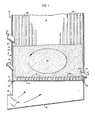
- the reference numeral 10 refers in general to an enclosure forming a major portion of a fluidized bed heat exchanger which may be in the form of a boiler, a combustor, a process reactor or any similar type device.
- the enclosure 10 consists of a front wall 12, a rear wall 14, and two sidewalls 16 and 17 respectively.
- each wall is formed by a plurality of vertically-extending tubes 18 disposed in a spaced, parallel relationship and connected together by a plurality of elongated fins 20 extending for the entire lengths of the tubes and connected to diametrically opposed surfaces of the tubes in a conventional manner.
- the upper portion of the enclosure 10 is not shown for the convenience of presentation, it being understood that it consists of a convection section, a roof and an outlet for allowing the combustion gases to discharge, also in a conventional manner.
- a bed of particulate material shown in general by the reference numeral 22 is disposed within the enclosure 10 and rests on a perforated plate 24 extending horizontally in the lower portion of the enclosure.
- the bed 22 can consist of a mixture of discrete particles of fuel material such as bituminous coal, and an adsorbent, such as limestone, for adsorbing the sulfur released by the combustion of the fuel material.
- An air plenum 26 is provided immediately below the plate 24 and an inlet 28 is provided through the plenum for distributing pressurized air from an external source (not shown) to the plenum under the control of a pair of dampers 30.
- An overbed feeder 32 extends through the front wall 12, receives particulate coal from inlet ducts or the like (not shown), and is adapted to feed the coal particles onto the upper surface of the bed 22.
- the feeder 32 can operate by gravity discharge or can be in the form of a spreader-type feeder or any other similar device. It is understood that a feeder can also be provided for discharging an adsorbent onto the bed 22, and would be constructed and arranged in a manner similar to the feeder 32.
- a drain pipe 34 extends through the wall 14 and has an inlet end portion 34a that registers with the interior of the enclosure 10 in communication with the lower portion of the bed 22.
- the pipe 34 is thus adapted to receive the spent bed material and functions to discharge the material from the enclosure 10 by gravity to a screw cooler, conveyor belt, or the like (not shown).
- a plurality of air distributors, or nozzles 36 communicate with the perforations of the plate 24 and each nozzle includes a vertically disposed tubular member that is secured to the plate in any conventional manner, such as by bolting or welding.
- the vertical portions of the nozzles 36 extend upwardly from the plate 24 for a predetermined distance into the bed 22 and their lower ends receive air from the plenum 26.
- Each nozzle 36 is bent at approximately a ninety degree angle to form a horizontally extending portion which is oriented in a manner to be described in detail later.
- the air from the plenum 26 enters the vertical portions of the nozzles 36 and discharges from the horizontal portions into the bed 22.
- the pitch of or number of nozzles per unit of bed area can be varied to cause zones of different bed density to achieve a desirable circulation.
- the nozzle type or size, at constant pitch can be varied to vary the air or gas flow.
- air flow, regulated by external dampers and plenum division plate can be varied in different zones of the bed. Since the air ultimately rises by convection in the enclosure 10 and discharges, along with the gaseous products of combustion, from an outlet (not shown) in the upper portion of the enclosure, the bed material extending above the horizontal nozzle portions is fluidized. Also, a dormant layer of particulate material is formed around the vertical portions of the nozzles 36 which acts to insulate the plate 24 from the heat generated in the heat exchanger extending above nozzles 36.
- a large majority of the nozzles 36 are oriented so that their horizontal discharge portions are directed towards the drain pipe 34 in general, and toward the rear wall 14 in particular, while a portion of the nozzles 36 (two rows in the example shown) adjacent the wall 14 are oriented so that their horizontal portions extend perpendicular to the horizontal portions of the other nozzles and directly towards the drain pipe 34.
- a momentum is imparted to the bed material which induces a circulation of the material in the direction indicated by dashed flow arrows in Fig. 1 to insure superior distribution, mixing and draining of the particulate material.
- a bed light-off burner 38 is provided through the front wall 12 immediately above the plate 24 for initially lighting off the bed during startup in a conventional manner.
- a pair of horizontal headers 40 are connected in fluid communication with the tubes 18 forming the frontwall 12 and the rear wall 14, respectively, and another horizontal header 42 is connected in fluid communication with the tubes 18 forming the sidewalls 16. It is understood that headers similar to the headers 40 and 42 are provided in communication with both ends of the sidewall 17 and the upper ends of the walls 12,14 and 16. As a result, a fluid to be heated can be sequentially or simultaneously passed through the walls 12, 14, 16 and 17 to pick up the heat from the fluidized bed in a conventional manner.
- the dampers 30 associated with the air plenum 26 are opened and pressurized air passes up through the plenum and into the inlet ends of the nozzles 36.
- the air flows upwardly through the vertical portions of the nozzles 36 before passing through the horizontal portions and discharging into the bed 22 at a plane above the plane of the plate 24.
- the air passes through the bed 22 in a generally upwardly direction towards the drain pipe 34.
- that portion of the particulate material in the bed 22 extending immediately above the nozzles 36 is fluidized in a manner to induce a circulation of the particulate material in the bed feeder 32 towards the drain pipe 34, while the portion extending between the latter ends and the upper surface of the plate 24 remains dormant, or stagnant.
- the light-off burner 38 is then fired to heat the material in the bed until the temperature of the material reaches a predetermined level, and additional particulate fuel is discharged from the feeder 32 while adsorbent material is discharged onto the upper surface of the bed 22 as needed.
- the light-off burner 38 is turned off while the feeder 32 continues to distribute particulate fuel to the upper surface of the bed in accordance with predetermined feed rates.
- an improved mixing and distribution of the particulate material is achieved due to the momentum imparted to the bed material and the improved circulation of the latter within the bed.
- the dormant layer of particulate material extending between the upper surface of the plate 24 and the horizontal portions of the nozzles 36 acts as an insulator for the plate 24.
- Fluid such as water
- Fluid to be heated is passed into the headers 40 and 42 where it passes simultaneously, or in sequence, through the tubes 18 forming the walls 12, 14, 16 and 17 to add heat from the fluidized bed to the fluid before it is passed to external apparatus for further processing.
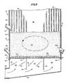
- a centrally located drain pipe 50 extends through the air plenum 26 and has an inlet end portion 50a that extends through, and projects slightly upwardly from, an enlarged opening formed in the plate 24.
- the drain pipe 50 is disposed midway between the walls 12 and 14 and midway between the walls 16 and 17, and thus in the central portion of the plate 24.
- Four feeders 32 are provided for discharging coal particles onto the upper surface of the bed 22, with two feeders extending through the front wall 12 and two extending through the rear wall 14.
- the nozzles 36 which are identical in construction to the nozzles of the previous embodiment, are oriented in a general direction towards the centrally located drain pipe 50. More particularly, the nozzles 36 extending between the front wall 12 and the drain pipe 50 are oriented to discharge the air in a general left-to-right direction as viewed in Figs. 1 and 4 while the nozzles extending between the rear wall 14 and the drain pipe 50 are oriented to discharge the air in a general right-to-left direction. Also, a portion of the nozzles 36 extending in three rows and between the side walls 16 and the drain pipe 50 are oriented in a direction perpendicular to the remaining nozzles and directly towards the drain pipe 50. Similarly, the remaining nozzles in these three rows and disposed between the sidewall 17 and the drain pipe 50 are also oriented in a perpendicular direction and towards the drain pipe 50.
- an improved mixing and distribution of the particulate material is also achieved as a result of the momentum imparted to the material and the improved circulation of the material within the bed.
- the reference numeral 110 refers in general to an enclosure forming a major portion of a fluidized bed heat exchanger which may be in the form of a boiler, a combustor, a process reactor of any similar type device.
- the enclosure 110 consists of a front wall 112, a rear wall 114, and two sidewalls 116, one of which is shown in Fig. 5.
- each wall is formed by a plurality of vertically-extending tubes 118 disposed in a spaced, parallel relationship and connected together by a plurality of elongated fins 120 extending for the entire lengths of the tubes and connected to diametrically opposed surfaces of the tubes in a conventional manner.
- the upper portion of the enclosure 110 is not shown for the convenience of presentation, it being understood that it consists of a convection section, a roof and an outlet for allowing the combustion gases to discharge, also in a conventional manner.
- a bed of particulate material shown in general by the reference numeral 122 is disposed within the enclosure 110 and rests on a perforated plate 124 extending horizontally in the lower portion of the enclosure.
- the bed 122 can consist of a mixture of discrete particles of fuel material such as bituminous coal, and a adsorbent, such as limestone, for adsorbing the sulfur released by the combustion of the fuel material.
- An air plenum 126 is provided immediately below the plate 124 and an inlet 128 is provided through the plenum for distributing pressurized air from an external source.
- Two partitions 130 and 132 are provided in the plenum 126 and divide the plenum into three sections 134,136 and 138.
- a pair of dampers 140 are adjustably mounted in the plenum section 134 and a pair of dampers 142 are adjustably mounted in the plenum section 136.
- the dampers 140 and 142 are of a conventional design and function to vary the flow rate of air (in terms of pounds per hour, or the like) through the plenum sections 134 and 136 respectively, with the dampers being set so that the flow rate through the section 136 is less than that through the section 138 and greater than that through the section 134, for reasons that will be explained in detail later.
- An overbed feeder 144 extends through the front wall 112, receives particulate coal from inlet ducts or the like (not shown), and is adapted to feed the coal particles onto the upper surface of the bed 122.
- the feeder 144 can operate by gravity discharge or can be in the form of a spreader-type feeder or any other similar device. It is understood that a feeder can also be provided for discharging an adsorbent onto the bed 122, and would be constructed and arranged in a manner similar to the feeder 144.
- a drain pipe 146 extends through the wall 114 and has an inlet end portion 146a that registers with the interior of the enclosure 110 in communication with the lower portion of the bed 122.
- the pipe 146 is thus adapted to receive the spent bed material as it migrates downwardly in the bed and functions to discharge the material from the enclosure 110 by gravity to a screw cooler, conveyor belt, or the like (not shown).
- a plurality of air distributors, or nozzles 150 communicate with the perforations through the plate 124, respectively, with each nozzle being in the form of a vertically disposed tubular member which is secured to the plate in any conventional manner, such as by bolting or welding, and which extends upwardly from the plate 124 for a predetermined distance into the bed 122.
- Air from the plenum 126 thus enters the lower end portions of the nozzles 150 and discharges, along with the gaseous products of combustion, from an outlet (not shown) in the upper portion of the enclosure.
- the bed material extending above the nozzles is fluidized by the air as it takes part in combustion of fuel from the feeder 144.
- a dormant layer of particulate material is formed around the vertical portions of the nozzles 150 which acts to insulate the plate 124 from the heat generated in the heat exchanger extending above the nozzles.
- the nozzles 150 are evenly spaced across the plate 124 with the nozzles of each row being offset from the nozzles of an adjacent row.
- the flow rate of air from the plenum 126 to the nozzles 150 is varied by selectively controlling the position of the dampers 140 and 142 and, therefore, the flow rate through the plenum sections 134 and 136 respectively. More particularly, the dampers 134 and 136 are normally positioned approximately as shown in Fig. 5 with the flow rate through the section 134 being less than that through the section 136.
- the flow rate through the section 136 is less than that through the section 138 (which has no dampers), it can be appreciated that the flow rate of air passing through the nozzles 150 and into the bed 122 increases in a direction from left to right, as viewed in Fig. 1, or in a direction from the feeder 144 to the drain pipe 146. This induces a circulation of the bed material in a direction from the feeder 144 to the drain pipe 146 and thus insures superior distribution and mixing of the particulate material, as will be explained in greater detail later.
- a bed light-off burner 152 is provided through the front wall 112 immediately above the plate 124 for initially lighting off the bed during startup in a conventional manner.
- a pair of horizontal headers 154 are connected in fluid communication with the tubes 118 forming the front wall 112 and the rear wall 114, respectively, and another pair of horizontal headers 156 are connected in fluid communication with the tubes 118 forming the sidewalls 116. It is understood that headers similar to the headers 154 and 156 are provided in communication with the upper ends of the walls 112, 114, and 116. As a result, a fluid to be heated can be sequentially or simultaneously passed through the walls 112, 113 and 116 to pick up the heat from the fluidized bed in a conventional manner.
- pressurized air is introduced into the plenum inlet 128 and passes up through the plenum 126 and into the plenum sections 134, 136 and 138.
- the air flows upwardly through the plenum sections 134, 136 and 138 and into the nozzles 150 with the flow rate through the sections 134 and 136 being under control of the dampers 140 and 142, respectively.
- the air then passes through the nozzles 150 and discharges into the bed 122 at a plane above the plate of the plate 124.
- the dampers 140 and 142 are adjusted to the approximate relative positions shown so that the flow rate of air through the plenum section 134 is less than that through the section 136.
- the light-off burner 152 is then fired to heat the material in the bed until the temperature of the material reaches a predetermined level, and additional particulate fuel and adsorbent material are discharged onto the upper surface of the bed 122 as needed.
- the light-off burner 152 is turned off while the feeder 144 continues to distribute particulate fuel to the upper surface of the bed in accordance with the predetermined feed rates.
- a superior mixing and distribution of the particulate material is achieved due to the momentum imparted to the bed material and the improved circulation of the latter within the bed. This increases the residence time of the particulate materials and thus considerably improves the reaction efficiency.
- the layer of particulate material extending between the upper surface of the plate 124 and the upper ends of the nozzles 150 is relatively dormant and thus acts as an insulator for the plate 124.
- Fluid such as water
- Fluid to be heated is passed into the headers 154 and 156 where it passes simultaneously, or in sequence, through the tubes 118 forming the walls 112, 114 and 116 to add heat from the fluidized bed to the fluid before it is passed to external apparatus for further processing.
- Figs. 6 and 7 is similar to that of the embodiment of Fig. 5 and identical components have been given the same reference numerals.
- the partitions and the dampers have been eliminated and the spacing of the perforations through the plate 124 and the resultant spacing of the nozzles 150 have been changed. More particularly, the spacing between the perforations and, therefore, between the nozzles 150, decreases in a general left-to-right direction as viewed in Figs. 6 and 7, i.e., in a direction between the front wall 112, where the feeder 144 is located and the rear wall 114, where the drain pipe 156 is located.
- the number of perforations and nozzles 150, and the resultant flow rate of air introduced into the bed 122 increases and the density of the bed decreases in the same direction.
- a momentum is imparted to the bed material in a manner similar to that of the previous embodiment, which induces a circulation of the materials in the direction shown by the dashed flow arrow in Fig. 6 and thus insures an improved distribution, mixing and residence time of the particulate material.
- the nozzles can take a different configuration from that discussed above, and the number, the specific locations, and the orientation of the nozzles can be varied as long as the above objectives and results are achieved. Also a bank, or series, of heat exchange tubes can be provided in the enclosures for circulating water in a heat exchange relationship with the bed 22 in a conventional manner.
Landscapes
- Engineering & Computer Science (AREA)
- Chemical & Material Sciences (AREA)
- Combustion & Propulsion (AREA)
- Mechanical Engineering (AREA)
- General Engineering & Computer Science (AREA)
- Organic Chemistry (AREA)
- Chemical Kinetics & Catalysis (AREA)
- Physics & Mathematics (AREA)
- Thermal Sciences (AREA)
- Fluidized-Bed Combustion And Resonant Combustion (AREA)
- Heat-Exchange Devices With Radiators And Conduit Assemblies (AREA)
Claims (7)
Applications Claiming Priority (4)
| Application Number | Priority Date | Filing Date | Title |
|---|---|---|---|
| US06/317,979 US4397102A (en) | 1981-11-03 | 1981-11-03 | Fluidized bed heat exchanger incorporating induced circulation utilizing directional and/or differential bed fluidization |
| US317979 | 1981-11-03 | ||
| US322310 | 1981-11-17 | ||
| US06/322,310 US4446629A (en) | 1981-11-17 | 1981-11-17 | Fluidized bed heat exchanger utilizing induced circulation |
Publications (2)
| Publication Number | Publication Date |
|---|---|
| EP0078706A1 EP0078706A1 (fr) | 1983-05-11 |
| EP0078706B1 true EP0078706B1 (fr) | 1986-06-11 |
Family
ID=26981250
Family Applications (1)
| Application Number | Title | Priority Date | Filing Date |
|---|---|---|---|
| EP82305824A Expired EP0078706B1 (fr) | 1981-11-03 | 1982-11-02 | Echangeur de chaleur à lit fluidifié avec circulation induite utilisant une fluidification directionnelle et/ou différentielle |
Country Status (3)
| Country | Link |
|---|---|
| EP (1) | EP0078706B1 (fr) |
| CA (1) | CA1186564A (fr) |
| IE (1) | IE53821B1 (fr) |
Families Citing this family (2)
| Publication number | Priority date | Publication date | Assignee | Title |
|---|---|---|---|---|
| CA1285375C (fr) * | 1986-01-21 | 1991-07-02 | Takahiro Ohshita | Thermoreacteur |
| US5138982A (en) * | 1986-01-21 | 1992-08-18 | Ebara Corporation | Internal circulating fluidized bed type boiler and method of controlling the same |
Citations (1)
| Publication number | Priority date | Publication date | Assignee | Title |
|---|---|---|---|---|
| GB1339287A (en) * | 1971-01-05 | 1973-11-28 | Coal Industry Patents Ltd | Apparatus for the combustion of solid fuels |
Family Cites Families (9)
| Publication number | Priority date | Publication date | Assignee | Title |
|---|---|---|---|---|
| FR2371227A1 (fr) * | 1976-11-17 | 1978-06-16 | Anvar | Procede de mise en contact de phases avec mise en suspension et en circulation naturelle d'au moins un produit solide a l'etat divise dans un fluide, et appareillage de mise en oeuvre |
| GB2010453B (en) * | 1977-12-17 | 1982-06-23 | Babcock & Wilcox Ltd | Fluidised bed combustion |
| GB2011045A (en) * | 1977-12-17 | 1979-07-04 | Babcock & Wilcox Ltd | Fluidized Bed Combustors |
| DE2811995A1 (de) * | 1978-03-18 | 1979-09-27 | Steag Ag | Wirbelbettfeuerung |
| US4240364A (en) * | 1979-05-03 | 1980-12-23 | Foster Wheeler Energy Corporation | Fluidized bed start-up apparatus and method |
| FR2474525A1 (fr) * | 1980-01-24 | 1981-07-31 | Sebel Expl Brevets Licences | Dispositifs pour gazeifier des combustibles solides semi-pulverises et application a des chambres de combustion precedemment chauffees par des bruleurs de combustibles liquides ou gazeux |
| SE8101964L (sv) * | 1980-04-09 | 1981-10-10 | Foster Wheeler Energy Corp | Fluidiserad-beddvermevexlare med luftfordelningsplatta |
| US4335661A (en) * | 1980-09-24 | 1982-06-22 | Foster Wheeler Energy Corporation | Fluidized bed heat exchanger having an air assisted bed drain |
| GB2085748B (en) * | 1980-10-24 | 1984-06-27 | Coal Industry Patents Ltd | Fluidised bed apparatus |
-
1982
- 1982-10-13 CA CA000413350A patent/CA1186564A/fr not_active Expired
- 1982-11-02 IE IE261982A patent/IE53821B1/en not_active IP Right Cessation
- 1982-11-02 EP EP82305824A patent/EP0078706B1/fr not_active Expired
Patent Citations (1)
| Publication number | Priority date | Publication date | Assignee | Title |
|---|---|---|---|---|
| GB1339287A (en) * | 1971-01-05 | 1973-11-28 | Coal Industry Patents Ltd | Apparatus for the combustion of solid fuels |
Also Published As
| Publication number | Publication date |
|---|---|
| CA1186564A (fr) | 1985-05-07 |
| IE822619L (en) | 1983-05-03 |
| IE53821B1 (en) | 1989-03-01 |
| EP0078706A1 (fr) | 1983-05-11 |
Similar Documents
| Publication | Publication Date | Title |
|---|---|---|
| US4404755A (en) | Fluidized bed heat exchanger utilizing induced diffusion and circulation | |
| US4349969A (en) | Fluidized bed reactor utilizing zonal fluidization and anti-mounding pipes | |
| US5682828A (en) | Fluidized bed combustion system and a pressure seal valve utilized therein | |
| US4761131A (en) | Fluidized bed flyash reinjection system | |
| CA1154335A (fr) | Echangeur de chaleur a lit fluidise pourvu d'un diffuseur d'air refroidi a l'eau et d'une tremie a poussiere | |
| US4253425A (en) | Internal dust recirculation system for a fluidized bed heat exchanger | |
| EP0567264B1 (fr) | Procédé de fluidification et tuyère pour la fluidification et le refroidissement | |
| KR960005759B1 (ko) | 유동상 반응기 | |
| US4436507A (en) | Fluidized bed reactor utilizing zonal fluidization and anti-mounding air distributors | |
| JPH0743230B2 (ja) | 熱交換器を有する流動床反応器装置及び方法 | |
| US4335661A (en) | Fluidized bed heat exchanger having an air assisted bed drain | |
| US4397102A (en) | Fluidized bed heat exchanger incorporating induced circulation utilizing directional and/or differential bed fluidization | |
| US4333909A (en) | Fluidized bed boiler utilizing precalcination of acceptors | |
| US4521976A (en) | Method of operating a fluidized bed heat exchanger utilizing induced circulation | |
| US4359968A (en) | Fluidized bed heat exchanger utilizing a baffle system | |
| US4446629A (en) | Fluidized bed heat exchanger utilizing induced circulation | |
| GB2075360A (en) | Water-cooled fluidised bed distributor plate | |
| US4809623A (en) | Fluidized bed reactor and method of operating same | |
| US5101576A (en) | Uni-directional fluidization nozzle and a fluidized bed system utilizing same | |
| US5105559A (en) | Flow-seal fluidization nozzle and a fluidized bed system utilizing same | |
| US5735682A (en) | Fluidized bed combustion system having an improved loop seal valve | |
| JPH06193827A (ja) | ストリッパークーラーを含む流動床反応器及び操作方法 | |
| CA1186564A (fr) | Echangeur de chaleur a lit fluidise et circulation induite | |
| US5286188A (en) | Uni-directional anti-backsifting fluidization nozzle and a fluidized bed system utilizing same | |
| US4526759A (en) | Fluidized bed reactor utilizing in-bed heat exchanger tubes which register with water wall tubes |
Legal Events
| Date | Code | Title | Description |
|---|---|---|---|
| PUAI | Public reference made under article 153(3) epc to a published international application that has entered the european phase |
Free format text: ORIGINAL CODE: 0009012 |
|
| AK | Designated contracting states |
Designated state(s): GB NL SE |
|
| 17P | Request for examination filed |
Effective date: 19831107 |
|
| GRAA | (expected) grant |
Free format text: ORIGINAL CODE: 0009210 |
|
| AK | Designated contracting states |
Kind code of ref document: B1 Designated state(s): GB NL SE |
|
| PGFP | Annual fee paid to national office [announced via postgrant information from national office to epo] |
Ref country code: NL Payment date: 19861130 Year of fee payment: 5 |
|
| PLBE | No opposition filed within time limit |
Free format text: ORIGINAL CODE: 0009261 |
|
| STAA | Information on the status of an ep patent application or granted ep patent |
Free format text: STATUS: NO OPPOSITION FILED WITHIN TIME LIMIT |
|
| 26N | No opposition filed | ||
| PG25 | Lapsed in a contracting state [announced via postgrant information from national office to epo] |
Ref country code: NL Effective date: 19890601 |
|
| NLV4 | Nl: lapsed or anulled due to non-payment of the annual fee | ||
| PGFP | Annual fee paid to national office [announced via postgrant information from national office to epo] |
Ref country code: SE Payment date: 19911030 Year of fee payment: 10 |
|
| PG25 | Lapsed in a contracting state [announced via postgrant information from national office to epo] |
Ref country code: SE Effective date: 19921103 |
|
| PGFP | Annual fee paid to national office [announced via postgrant information from national office to epo] |
Ref country code: GB Payment date: 19941025 Year of fee payment: 13 |
|
| EUG | Se: european patent has lapsed |
Ref document number: 82305824.3 Effective date: 19930610 |
|
| PG25 | Lapsed in a contracting state [announced via postgrant information from national office to epo] |
Ref country code: GB Effective date: 19951102 |
|
| GBPC | Gb: european patent ceased through non-payment of renewal fee |
Effective date: 19951102 |