EP0079201A2 - Tape players - Google Patents
Tape players Download PDFInfo
- Publication number
- EP0079201A2 EP0079201A2 EP82305857A EP82305857A EP0079201A2 EP 0079201 A2 EP0079201 A2 EP 0079201A2 EP 82305857 A EP82305857 A EP 82305857A EP 82305857 A EP82305857 A EP 82305857A EP 0079201 A2 EP0079201 A2 EP 0079201A2
- Authority
- EP
- European Patent Office
- Prior art keywords
- pair
- reel
- moving member
- moving
- rotating
- Prior art date
- Legal status (The legal status is an assumption and is not a legal conclusion. Google has not performed a legal analysis and makes no representation as to the accuracy of the status listed.)
- Granted
Links
Images




Classifications
-
- G—PHYSICS
- G11—INFORMATION STORAGE
- G11B—INFORMATION STORAGE BASED ON RELATIVE MOVEMENT BETWEEN RECORD CARRIER AND TRANSDUCER
- G11B15/00—Driving, starting or stopping record carriers of filamentary or web form; Driving both such record carriers and heads; Guiding such record carriers or containers therefor; Control thereof; Control of operating function
- G11B15/18—Driving; Starting; Stopping; Arrangements for control or regulation thereof
- G11B15/26—Driving record carriers by members acting directly or indirectly thereon
- G11B15/32—Driving record carriers by members acting directly or indirectly thereon through the reels or cores on to which the record carrier is wound
-
- G—PHYSICS
- G11—INFORMATION STORAGE
- G11B—INFORMATION STORAGE BASED ON RELATIVE MOVEMENT BETWEEN RECORD CARRIER AND TRANSDUCER
- G11B15/00—Driving, starting or stopping record carriers of filamentary or web form; Driving both such record carriers and heads; Guiding such record carriers or containers therefor; Control thereof; Control of operating function
- G11B15/02—Control of operating function, e.g. switching from recording to reproducing
- G11B15/10—Manually-operated control; Solenoid-operated control
-
- G—PHYSICS
- G11—INFORMATION STORAGE
- G11B—INFORMATION STORAGE BASED ON RELATIVE MOVEMENT BETWEEN RECORD CARRIER AND TRANSDUCER
- G11B15/00—Driving, starting or stopping record carriers of filamentary or web form; Driving both such record carriers and heads; Guiding such record carriers or containers therefor; Control thereof; Control of operating function
- G11B15/18—Driving; Starting; Stopping; Arrangements for control or regulation thereof
- G11B15/44—Speed-changing arrangements; Reversing arrangements; Drive transfer means therefor
Definitions
- tuner pack which is formed by accommodating a tuner circuit portion, which carries out the reception, tuning, detection and amplification of the radio waves, in a casing of approximately the same shape as the tape cartridge, and fitting this tuner pack in the tape player, in place of a tape cartridge.
- an object of the present invention to provide a tape player which is of simple construction.
- Another object of the present invention is to provide a tape player which is improved as regards its operative ability.
- a still further object of the invention is to provide a tape player of which the size is effectively made small.
- apparatus for controlling movement of a tape disposed on at least one reel, the reel defining a hole therethrough, the apparatus comprising: a moving member adapted for co-operation with the said hole for rotating the said reel, the member being both rotatable about an axis and slidable along this axis; means for rapidly rotating the said moving member; means for slowly rotating the said moving member; first means for coupling the said moving member and the said rapid rotating means when the said moving member is slid in a first direction; and second means for coupling the said moving member and the said slow rotating means when the said moving member is slid in a second direction.
- apparatus for controlling movement of tape disposed on a pair of reels, each of the reels defining a hole therethrough
- the apparatus comprising: a pair of moving members, adapted for co-operation with respective ones of the said holes for rotating the said reels, the said members being rotatable about first and second axis respectively, and slidable along the said first and second axes respectively; a pair of means for rotating the said pair of moving members respectively, in opposite directions, and a pair of coupling means, one of the said coupling means being for coupling one of the said pair of moving members and a corresponding one of the said pair of rotating means when one of the said moving members is slid in one direction, and the other of the said coupling means being for coupling the other of the said pair of moving members and the other of the said pair of rotating means when another of the said moving members is slid in one direction.
- a casing or cabinet 11 is formed approximately the same size as seen in its front view as a cartridge case, for example a cassette case, which holds a tape cassette.
- a cartridge case for example a cassette case, which holds a tape cassette.
- One planar surface of cabinet 11 forms a lid 12 for covering a tape cassette loaded in cabinet 11.
- Lid 12 is supported in such a way that it is able to be opened and closed by being rotated in the directions of arrows A and B in Figure 1b by a hand of the user.
- Lid 12 is slightly locked in both the open and closed positions, so that it does not rattle.
- Lid 12 is provided with a cassette holder which will be described in detail later.
- a fast forward operating element 19 and a rewind operating element 20 are arranged at positions corresponding to reel shafts 17 and 18 (which become take-up reels during fast forward and rewind operations) on lid 12, so as to include rotary shafts 171, 181 of reel shafts 17, 18.
- Fast forward and rewind operating elements 19, 20 are arranged so as to be capable of depressing rotary shafts 171, 181, to be described later, of reel shafts 17, 18 in their axial directions.
- Both ends of support shaft 24 are supported by bearing parts 197, 207 formed on the underside of lid 12.
- fast forward and rewind operating elements 19, 20 are rotationally biased outwards from lid 12 about support shaft 24 by means of leaf springs 198, 208, respective ends of which are supported on support shaft 24, and the other ends of which press against the central portions of fast forward and rewind operating elements 19, 20.
- these portions are checked by abutment elements (not shown) which are formed on peripheries of the through-holes of lid 12 through which fast forward and rewind operating elements 19, 20 are inserted, and the edges of fast forward and rewind operating elements 19, 20.
- Head chassis 31 is biased for rotation in the direction of the arrow D in Figure 6 about shaft 311, by means of a torsion spring (not shown), one end of which abuts the side of head chassis 31, and the other end of which is abutted by cassette holder 28, the torsion spring being wound around shaft 311.
- Pinch lever 301 is biased for rotation in the direction of the arrow C in the figure about shaft 311 by means of a coil spring (not shown), which extends between pinch lever 301 and head chassis 31.
- a shaft 302 of pinch roller 30 is arranged to extend so that shaft 302 freely fits into a slot 312 formed in head chassis 31.
- Gearwheel 42 is in mesh with gearwheel 35 of flywheel 33, and gearwheel 43 is in mesh with gearwheel 41 of reel shaft 17. Gearwheel 42 is then in a position in which gearwheel 42 would mesh with gearwheel 40 on reel shaft 17, but there is a vertical gap between these gearwheels 42, 40 as seen in Figure 9, so that these gearwheels 42, 40 fail to mesh with each other.
- a shaft 254 is provided on main chassis 25 approximately midway between reel shaft 18 and shaft 252.
- a bearing member 51 of approximately cylindrical shape is provided on shaft 254 in such a way that bearing member 51 is freely rotatable and also freely slidable along the direction of shaft 254, i.e., in the vertical direction in Figure 10.
- a rewind lever 52 and a gearwheel 53 are fitted on to bearing member 51.
- a coil spring 512 is provided between the lower end in Figure 10 of bearing member 51 and a washer 511, which is fitted on to the lower part in the figure of shaft 254. Bearing member 51 is thus biased upwards in the figure, and in this condition gearwheel 53 meshes with gearwheel 50 of reel shaft 18.
- leaf switch 56 is put in the ON condition, and reel shaft 17 is locked in its depressed, i.e. operated, position. with this depression of reel shaft 17, rotary shaft 171 is also then lowered downwards in the figure, and gearwheels 40, 41, which are mounted on rotary shaft 171, are also shifted in the same direction.
- gearwheel 41 comes out of mesh with gearwheel 43
- gearwheel 40 comes into mesh with gearwheel 42.
- the turning force of flywheel 33 in the anti-clockwise direction in Figure 6 is transmitted to reel cap 38 through gearwheels 35, 42, and 40 and rotary shaft 171.
- Reel cap 38 is therefore rotated at high speed in the anti-clockwise direction in Figure 6, so that fast forward operation of the tape occurs.
- stop operating element 22 is supported on cassette holder 28, so that stop operating element 22 is freely slidable in the vertical direction in Figure 13.
- stop operating element 22 is supported on cassette holder 28 in such a way that stop operating element 22 is prevented from sliding off upwards in Figure 13.
- Operating shaft 221 extends downwards in Figure 13 from the undersurface in the figure of stop operating element 22, and coil spring 222 is mounted on the lower end in the figure of operating shaft 221. This is then mounted on the base surface of drive portion 223 having an approximately conical shape.
- First abutment portion 541 of locking lever 54 is here pressed against taper portion 224 of drive portion 223, by means of the biasing force of spring 545 (see Figure 6).
- stop operating element 22 is biased upwards in Figure 13 by means of spring 222 towards the position in which further upward movement is restricted.
- the tape player explained in this embodiment is provided with an automatic stop mechanism whereby the tape player is automatically brought into a stopped condition when the tape reaches its end during a play back condition.
- an end portion of friction lever 58 is provided in the lower portion of gearwheel 43 in Figure 9, with a well-known type of friction mechanism arranged between them.
- friction lever 58 is biased towards the direction of rotation.
- Slot 581 is formed at the other end of friction lever 58, and projecting pin 591 is freely fitted into one end portion of detection lever 59 in slot 581.
- Detection lever 59 is freely rotatably supported at about its middle by shaft 592 which projects from main chassis 25.
- stop slider 57 As explained earlier, is supported on main chassis 25 in such a way that stop slider 57 is freely slidable in the directions of the arrow in the figure. Stop slider 57 is normally held in the intermediate position shown in Figure 14a by means of torsion spring 577 shown in Figure 6. Thus, projections 578, 579 formed at-opposite ends of stop slider 57 are positioned at the lower part in Figure 14a of taper portions 372, 472 of locking members 37, 47 of reel shafts 17, 18.
- reel shaft 18 is pressed downwards in the figure and as explained earlier is locked in the depressed position by means of third abutment portion 543 of locking lever 54.
- taper portion 472 of locking member 47 of reel shaft 18 is pressed against projection 579 of stop slider 57, so that stop slider 57 is slid to the right in Figure 14b against the biasing force of torsion spring 577.
- Projection 572 of stop slider 57 is then positioned approximately contacting bearing member 36 of reel shaft 17, and projection 578 is interposed between flange portion 361 of bearing member 36 and abutment portion 373 of locking member 37.
- Projection 579 of stop slider 57 is then positioned in between flange portion 461 of bearing member 46 of reel shaft 18 and stop portion 473 of locking member 47. Consequently, even if an attempt is made to operate rewind operating element 20 in the fast forward condition, stop portion 473 of locking member 47 of reel shaft 18 contacts projection 579 of stop slider 57, preventing operating element 20 from being pressed into its normal depressed position.
- a high space factor is able to be achieved with a very simple construction and assembly is able to be facilitated by the formation of through-hole 128 in the side portion of lid 12, introducing support shaft 24 into lid 12 through through-hole 128, by simply providing bearing portions 191 to 197 and 201 to 207 with through-holes through which support shaft 24 is able to be inserted.
- through-holes 128, 129 are formed in both of side portions 125, 127 of lid 12, a through- holde could of course be formed in one side only.
- Figure 15 shows the configuration of reel caps 38, 48 of reel shafts 17, 18.
- Blades 381, 481 of approximately diamond-shape in side view are formed on the outer surface of approximately cylindrical reel caps 38, 48.
- Blades 381, 481 are able to abut with projections of reel hubs of tape cassettes for the purpose of transmitting the turning force of reel caps 38, 48 to the reel hubs.
- the projections (in the case of an ordinary compact tape cassette, six such projections for each reel hub) project in respective peripherally inwards directions from reel hubs.
- the operation of blade 381 of reel cap 38, for example, will be explained with reference to Figure 16 (the operation of blade 481 the same as that of reel cap 38, so an explanation of blade 481 is omitted).
- blades 381, 481 of reel caps 38, 48 are shown in Figures 17a to 17c.
- Figures 17a, 17c show the shape of reel cap 38
- Figure 17b shows the shape of reel cap 48.
- the explanation will be mainly directed to reel cap 38.
- blade 381 of reel cap 38 projects with an inclination such that it is approximately tangential to the peripheral side face of reel cap 38.
- This projecting face comprises a perpendicaular portion 384 formed parallel to the centre line of reel cap 38, and in approximately its upper half in Figure 17a, inclined portion 382 having an angle with respect to the centre line.
- Reel cap 48 is formed with perpendicular portion 484 and inclined portion 482, similar to perpendicular portion 384 and inclined portion 382 of reel cap 38, but directed oppositely to the corresponding portions on reel cap 38.
- first drive portion 212 which is integral with playback operating element 21, is shifted in the direction such as to separate from first abutment portion 541 of locking lever 54, i.e. in the direction of arrow I in the Figure 22, thereby returning playback operating element 21 to the non- operated position.
- Figures 25 and 26 show embodiments of the tape player described above of different external appearance and shape. Parts which are the same as those described above are given the same reference numerals and a detailed explanation thereof is omitted.
- the position where both reel shafts 17, 18 are regulated means a shallow position where both locking members 37, 47 are not locked together with second and third abutment portions 542, 543 of locking lever 54.
- both reel shafts 17, 18 are not locked at the operative position even if stop operating element 22 is operated.
- the operative stroke of stop operating element 22 is short in comparison with the case where fast forward and rewind operating elements 19, 20 are operated alone.
- Figure 29 shows a case wherein a pause operating member 70 is mounted using one opening of through-hole 71 which is one of a pair of through-holes of a tape cassette designed for capstans of tape players capable of passing therethrough.
- a pause operating member 70 is mounted using one opening of through-hole 71 which is one of a pair of through-holes of a tape cassette designed for capstans of tape players capable of passing therethrough.
- tape cassette 13 is mounted to tape cassette holding portion 14 (see Figure 1b)
- capstan 26 is passed through the other of the pair of through-holes for capstans (which is not shown in the figure but is the same as through hole 71 of Figure 29)
- pause operating member 70 is passed through hole 71 which is one of the holes for capstans.
- Pause operating member 70 is supported in such a way as to be slidable along through-hole 71, and is connected to a well known push-pull mechanism at the lower portion in the figure of main chassis 25 and,at the same time, is in engagement with a leaf switch 72.
- a pause operating element 73 in lid 12 in the same way as the other operating elements 19, 20, and the like. If pause operating element 73 is once operated in such a manner as to be pressed, pause operating member 70 is pressed downwards in the figure and locked in position.
- the operating elements are passed through various kinds of openings or through-holes (the through-holes through which capstan 26 is passed, the through-holes through which guide pins are passed and the through-holes through which reel shafts 17, 18 are passed) which are formed in the direction of the thickness of tape cassette 13, so as to make it possible to operate from the side of the planar portion of tape cassette 13, it is not necessary to especially provide the spaces for putting the operating elements within cabinet 11, which is advantageous in view of the use of the space and which will fully contribute to, in particular, making small the size of the tape player.
Landscapes
- Unwinding Webs (AREA)
- Casings For Electric Apparatus (AREA)
Abstract
Description
- The present invention relates to tape players.
- Tape players have recently become popular which are of small size and lightweight, se as to be portable, in particular, which are of a two-way stereo type exclusively for playback use using headphones. Thus, the user can enjoy the playback of the tape while wearing the headphones and, for example, walking around. Such portable tape players of the type exclusively intended for use with headphones have already been reduced in size as far as possible. At present, they have about the same size as the cartridge case which holds the tape cartridge.
- By the way, when the tape player is miniaturised to about the same size as the cartridge case, what is particularly required is to simplify its construction and to improve its operability and convenience in use, by improving a mechanism for driving tape and an arrangement of the various operating elements for putting the tape player in the various operating conditions such as playback, fast forward, rewind, and the stop condition. More specifically, the operating elements of previous small tape players were also small in size, in proportion to the tape player itself, and were concentrated in one place due to the relationship with the tape player mechanism. This of course made them difficult to operate and increased the risk of erroneous operation. Further, the tape drive mechanisms were complicated. Thus, it has been required that the operating elements should have such a configuration as to be large enough to be easily operated by the user and should have a comfortable separation from each other so that neighbouring elements are not unintentionally operated, thereby providing a tape player that is not only conveniently portable but which also has excellent operability and wherein there is no risk of erroneous operation.
- Apart from simple playing back a tape, some such small tape players can receive radio transmissions. This is achieved by use of a tuner unit (hereinafter referred to as a "tuner pack"), which is formed by accommodating a tuner circuit portion, which carries out the reception, tuning, detection and amplification of the radio waves, in a casing of approximately the same shape as the tape cartridge, and fitting this tuner pack in the tape player, in place of a tape cartridge. A development along the lines of the requirements already mentioned is also urgently required for such small tape players capable of using a tuner pack.
- It is,therefore, an object of the present invention to provide a tape player which is of simple construction. Another object of the present invention is to provide a tape player which is improved as regards its operative ability.
- A further object of the present invention is to provide a tape player of which construction is highly integrated without useless parts.
- A still further object of the invention is to provide a tape player of which the size is effectively made small.
- According to one aspect of the present invention, there is provided apparatus for controlling movement of tape disposed on at least one reel, the reel defining a hole therethrough, the apparatus comprising: a moving member adapted for co-operation with the said hole for rotating the said ree], the member being rotatable about an axis and slidable along this axis; means for rotating the said moving member; end means for coupling the said rotating means and the said moving member when the moving member is slid in one direction.
- According to another aspect of the present invention, there is provided apparatus for controlling movement of a tape disposed on at least one reel, the reel defining a hole therethrough, the apparatus comprising: a moving member adapted for co-operation with the said hole for rotating the said reel, the member being both rotatable about an axis and slidable along this axis; means for rapidly rotating the said moving member; means for slowly rotating the said moving member; first means for coupling the said moving member and the said rapid rotating means when the said moving member is slid in a first direction; and second means for coupling the said moving member and the said slow rotating means when the said moving member is slid in a second direction.
- According to another aspect of the present invention, there is provided apparatus for controlling movement of tape disposed on a pair of reels, each of the reels defining a hole therethrough, the apparatus comprising: a pair of moving members, adapted for co-operation with respective ones of the said holes for rotating the said reels, the said members being rotatable about first and second axis respectively, and slidable along the said first and second axes respectively; a pair of means for rotating the said pair of moving members respectively, in opposite directions, and a pair of coupling means, one of the said coupling means being for coupling one of the said pair of moving members and a corresponding one of the said pair of rotating means when one of the said moving members is slid in one direction, and the other of the said coupling means being for coupling the other of the said pair of moving members and the other of the said pair of rotating means when another of the said moving members is slid in one direction.
- According to another aspect of the present invention, there is provided apparatus for controlling movement of tape disposed on a pair of reels, each of the reels defining a hole therethrough, the apparatus comprising: a pair of moving members, adapted for co-operation with respective ones of the said holes, for rotating the said reels, the said members being rotatable about first and second axes respectively, and slidable along the said first and second axes respectively; a pair of means for rapidly rotating the said pair of moving members respectively, in opposite directions; a pair of coupling means, one of the said coupling means being for coupling one of the said pair of moving members and a corresponding one of the said pair of rapid rotating means when one of the said moving members is slid in one direction, and the other of the said coupling means being for coupling the other of the said pair of moving members and the other of the said pair of rapid rotating means when another of the said moving members is slid in one direction; means for slowly rotating one of the said pair of moving members in the same direction as the rapid rotating means causes the said one of the said pair of moving membe_s to rotate; and means for coupling the said one of the said pair of moving members and said slow rotating means when the said one of the said pair of moving members is slid in another direction opposite the said one direction.
- According to another aspect of the present invention, there is provided apparatus for driving a cartridge tape, the cartridge tape including a housing defining a hole therethrough, at least one reel and tape wound on the reel, the apparatus comprising: means adapted for receiving the said cartridge tape; a moving member adapted for rotating the said reel, the moving member being mounted on the said receiving means; means for driving the said moving member; and means for controlling the operation of the said driving means, the controlling means including an actuating member extending through the said hole when said cartridge tape is located on the said receiving means.
- According to another aspect of the present invention, there is provided apparatus for driving a cartridge tape, the cartridge tape including a housing defining a hole therethrough, at least one reel and tape wound on said reel, the apparatus comprising: means adapted for receiving the said cartridge tape; a moving member adapted for rotating the said reel, the moving member being mounted on the said receiving means; means for driving the said moving member; and means for interrupting the operation of the said driving means, the interrupting means including an actuating member extending through the said hole when the said cartridge tape is located on the said receiving means.
- The present invention will now be described by way of example, with reference to the accompanying drawings, in which :-
- Figures 1a and 1b are a front view and a side view showing a tape player;
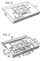
- Figure 2 is a perspective view showing the lid of the tape player;
- Figure 3 is a perspective view showing how fast- forward and rewind operating elements are mounted on the lid;
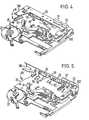
- Figure 4 is a perspective view showing the mechanism of the tape player, and the external appearance of a head unit and cassette holder;
- Figure 5 is a perspective view showing the cassette holder of Figure 4 in its open condition;
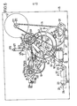
- Figure 6 is a view showing details of the construction of the tape player mechanism;
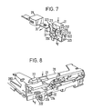
- Figure 7 is a perspective view showing the relationship between a playback operating element and the head unit;
- Figure 8 is a perspective view showing the playback operating element in an operated condition;
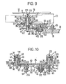
- Figures 9 to 12 are views given for explanation of the action of the tape player mechanism;
- Figure 13 is a perspective view showing details of a stop operating element;
- Figures 14a and 14b are views given for explanation of the action of a stop slider;
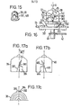
- Figures 15 and 16 are a perspective view and a side view showing the shape and operation of a reel cap blade in one embodiment of a cassette tape player;
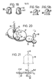
- Figures 17a to 17c, Figure 18 and Figures 19a and 19b are side views showing other possible shapes of the reel cap blades;
- Figure 20 is a perspective view showing the shape of gearwheels of the tape player mechanism;
- Figure 21 is a side view showing the action of these gearwheels;
- Figure 22 is a perspective view showing the relationship between the playback operating element and a locking lever;
- Figures 23a and 23b are a front view and a back view of a tuner pack;
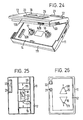
- Figure 24 is a perspective view showing how the tuner pack is fitted into the cassette holder;
- Figures 25 and 26 are front views showing the external appearance of tape players constituting different embodiments of the present invention;
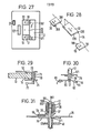
- Figure 27 is a front view showing a tape player which is modified from that of Figure 1a;
- Figure 28 is a disassembled perspective view showing operating elements of Figure 27;
- Figure 29 is an explanatory view of a pause operating mechanism;
- Figure 30 is a side view in cross-section showing a modified example of a reel shaft portion; and
- Figure 31 is a side view in cross-section showing further modifications of the reel shaft portion.
- Throughout the drawings, like reference letters and numerals will be used to designate like or equivalent elements. Referring first to Figures 1a and 1b, a casing or
cabinet 11 is formed approximately the same size as seen in its front view as a cartridge case, for example a cassette case, which holds a tape cassette. One planar surface ofcabinet 11 forms alid 12 for covering a tape cassette loaded incabinet 11.Lid 12 is supported in such a way that it is able to be opened and closed by being rotated in the directions of arrows A and B in Figure 1b by a hand of the user.Lid 12 is slightly locked in both the open and closed positions, so that it does not rattle.Lid 12 is provided with a cassette holder which will be described in detail later. The cassette holder is linked with the opening and closing actions oflid 12, and can hold a tape cartridge, for example atape cassette 13 indicated by the double-dotted chain lines in Figure 1b.Cabinet 11 contains amechanism accommodating part 15 in which a tapecassette holding part 14 is arranged capable of accommodatingtape cassette 13, whenlid 12 is in its closed condition, and the tape player mechanism, circuitry, and battery holder, etc., which will be described later. Ahead unit 16 is also arranged insidecabinet 11, opposite the exposed face oftape cassette 13, and equipped with a playback head and pinch roller etc., to be described later. Both thehead unit 16 and the cassette holder are linked for conjoint movement with the opening and the closing operation oflid 12. - As shown in Figure la, a pair of
reel shafts tape cassette 13, are supported in tapecassette holding part 14. A fastforward operating element 19 and arewind operating element 20 are arranged at positions corresponding toreel shafts 17 and 18 (which become take-up reels during fast forward and rewind operations) onlid 12, so as to includerotary shafts reel shafts operating elements rotary shafts reel shafts - A
playback operating element 21 and astop operating element 22 are also arranged onlid 12, so as to be operable in such a way as to be depressed practically perpendicularly to the plane oflid 12. Theseelements head unit 16, i.e. not facing the planar portion oftape cassette 13. Awindow 23 is defined in approximately the centre of lid 12:Window 23 is formed, for example, of transparent acrylic sheet and is arranged so that it at least partially overlies the well known transparent tape window formed in the planar portion oftape cassette 13. Specifically, the right end in Figure 1a ofwindow 23 partly overliesreel shafts window 23. Concerning that the running condition of tape should be seen from outside, fast forward and rewindoperating elements -
Lid 12 defines a taperedslot 121 expanding outwardly from tapecassette holding portion 14, in a position between fast forward and rewindoperating elements elements Slot 121 is provided so that a tuning operation during a radio reception is able to be performed when using a tuner pack in place oftape cassette 13. Thus apart from being able to play back tapes, radio transmissions can also be received using the tuner pack. This is achieved by using a tuner pack which is formed by accommodating a tuner circuit unit for carrying out reception, tuning, detection and amplification of radio waves, in a casing of approximately the same shape astape cassette 13, and fitting into tapecassette holding portion 14 in place oftape cassette 13. The tuning operation is performed by a tuning selector provided on the tuner pack so as to select the required transmitting station, whereupon the radio wave received is detected and amplified, then fed to a main amplifier circuit in the tape player through connection terminals, and reproduced by headphones.Lid 12 is then in a closed condition and the tuning selector projects to the outside throughslot 121, so that the tuning operation can be carried out without openinglid 12. A volume controller, a tape type (normal, chrome, metal, etc.) a changeover switch and a headphone jack, etc. are arranged on the side of thecabinet 11, though not shown in Figures la and 1b. - In Figure 2,
lid 12 has been removed fromcabinet 11. Through-holes playback operating element 21 and stop operatingelement 22 are inserted are respectively formed inlid 12. As shown in Figure 3, fourside portions 124 to 127 form side faces ofcabinet 11. Fast forward and rewindoperating elements lid 12. Pairs of bearingparts operating elements parts lid 12 outside bearingparts forward operating element 19. Further pairs of bearingparts lid 12 outside bearingparts rewind operating element 20. Thus, all bearingparts 191 to 196 and 201 to 206 are arranged on the sar.e straight line. Through-holes side portions lid 12, at positions corresponding to the two ends of this line. As shown in Figure 3 by broken lines, asupport shaft 24 is inserted from outside into through-hole 128 inside portion 125 oflid 12. Thus, fast forward and rewindoperating elements lid 12 bysupport shaft 24 passing through all of bearingparts 191 to 196 and 201 to 206. Both ends ofsupport shaft 24 are supported by bearingparts lid 12. At approximately the centre of these underparts, fast forward and rewindoperating elements lid 12 aboutsupport shaft 24 by means ofleaf springs support shaft 24, and the other ends of which press against the central portions of fast forward and rewindoperating elements lid 12 through which fast forward and rewindoperating elements operating elements operating elements leaf springs operating elements operating elements rotary shafts reel shafts - Figure 4 is an overall external view of the tape player mechanism,
head unit 16, andcassette holder 28, etc. that are installed in themechanism accommodating unit 15. Amain chassis 25 of the tape player mechanism supportsreel shafts reel shafts capstan 26 is a rotary shaft of a flywheel as described later and amotor 27 which is operably connected to reelshafts capstan 26 are respectively supported onmain chassis 25 together withreel shafts Cassette holder 28 is supported at one end ofmain chassis 25 so thatcassette holder 28 is able to rotate in the directions of the arrows A and B in Figure 4. Holdingelements cassette holder 28 at opposite ends thereof, so as to hold both end portions of tape cassette 13 (not shown). Aplayback head 29 and apinch roller 30 that is able to be brought into contact with or moved away fromcapstan 26 are respectively supported in approximately the middle ofcassette holder 28. Playback and stop operatingelements cassette holder 28. -
Lid 12 is fitted on tocassettte holder 28 so as to cover it. Playback and stop operatingelements holes 122, 123 (see Figure 2) formed inlid 12. Whenlid 12 is put into an open condition,cassette holder 28, moving conjointly withlid 12, is rotated in the direction of the arrow A in Figure 4, so as to assume the position shown in Figure 5.Playback head 29 andpinch roller 30 are then shifted together withcassette holder 28. - The detailed construction of the tape player mechanism and
head unit 16 will now be explained. As seen from Figure 6, playback operating element 21 (indicated by double-dotted chain lines in the lower part of the figure) onmain chassis 25 is supported on cassette holder 28 (not shown in Figure 6). Ahead chassis 31 is supported oncassette holder 28 on the right ofplayback operating element 21 in the figure, by means of ashaft 311.Shaft 311 supportshead chassis 31 so thathead chassis 31 is able to freely rotate in the directions of the arrows C and D in Figure 6.Playback head 29 is mounted at the left-hand end ofhead chassis 31 in the figure. One end of apinch lever 301 is freely rotatably supported onshaft 311. Pinchroller 30 is also freely rotatably supported on the other end ofpinch lever 301. -
Head chassis 31 is biased for rotation in the direction of the arrow D in Figure 6 aboutshaft 311, by means of a torsion spring (not shown), one end of which abuts the side ofhead chassis 31, and the other end of which is abutted bycassette holder 28, the torsion spring being wound aroundshaft 311. Pinchlever 301 is biased for rotation in the direction of the arrow C in the figure aboutshaft 311 by means of a coil spring (not shown), which extends betweenpinch lever 301 andhead chassis 31. A shaft 302 ofpinch roller 30 is arranged to extend so that shaft 302 freely fits into aslot 312 formed inhead chassis 31. The rotation ofpinch lever 301 due to the coil spring in the direction of the arrow C therefore continues until shaft 302 abuts the upper end in the figure ofslot 312. As shown in Figure 7, anabutment portion 321 extending from one end of aplayback drive number 32 abuts the lower left hand end in Figure 6 ofhead chassis 31.Playback drive member 32 is supported so thatplayback drive member 32 is free to rotate in the directions of the arrows E and F in Figure 7, by means of a shaft (not shown), which is inserted into a through-hole 323 formed in a mountingportion 322 extending from the other end ofplayback drive member 32. The shaft for supportingplayback drive member 32 projects frommain chassis 25.Playback operating element 21 referred to earlier is supported oncassette holder 28 in a position aboveplayback drive member 32, in such a way thatplayback operating element 21 is free to slide in the vertical direction in Figure 7, and prevented from coming out by being slid upwards in Figure 7. -
Playback operating element 21 has an operatingshaft 211 extending downwards from the lower portion ofplayback operating element 21. Operatingshaft 211 is mounted on a firstfirst drive portion 212 whose surface is shaped as an approximately conical surface. The head portion offirst drive portion 212 is joined to the head portion of asecond drive portion 214 whose surface is also shaped as an approximately conical surface, through ashaft 213. The base surface ofsecond drive portion 214 faces abase surface 324 ofplayback drive member 32. Consequently, the rotation ofhead chassis 31 in the direction of the arrow D in Figure 6,due to the torsion spring for biasinghead chassis 31,continues and the free end ofhead chassis 31 depressesabutment portion 321 ofplayback drive member 32.Playback drive member 32 is caused to rotate in the direction of arrow E in Figure 7 so thatbase portion 324 ofplayback drive member 32 depresses the base surface ofsecond drive portion 214. Then,playback operating element 21 slides upwards in the figure, until further ' rotation ofplayback drive member 32 is prevented by being arrested. Let us now assume thatplayback operating element 21 is operated by being depressed downwards, as shown in Figure 8. When this happens, the base surface ofsecond drive portion 214 depressesbase portion 324 ofplayback drive member 32.Playback drive member 32 is caused to rotate in the direction of arrow F in Figure 8. As a result,abutment portion 321 ofplayback drive member 32 depresses the free end ofhead chassis 31 against the biasing force of the torsion spring for biasinghead chassis 31, andhead chassis 31 is thereby rotated in the direction of arrow C in Figure 6. At this time,playback head 29 is brought into contact with a tape (not shown) oftape cassette 13. Pinchroller 30 is also pressed againstcapstan 26, with the tape interposed. Pinchroller 30 is set in a positional relationship such thatpinch lever 301 is pressed back in the direction of arrow D in Figure 6 aboutshaft 311 against the biasing force of the coil spring which biases pinchlever 301 for rotation in the direction of arrow C in Figure 6, whenpinch roller 30 presses againstcapstan 26. -
Playback operating element 21 is locked in the depressed position shown in Figure 8. (The locking mechanism will be described later). Again as shown in Figure 6,motor 27 is mounted in the upper right-hand region in the figure ofmain chassis 25. Arotary shaft 271 ofmotor 27 has mounted on it a small-diameter pulley 272. On the other hand, aflywheel 33 is freely rotatably supported in the bottom right-hand region in the figure ofmain chassis 25.Flywheel 33 andpulley 272 are connected through abelt 34 so that turning force is able to be transmitted between them. The rotary shaft offlywheel 33 iscapstan 26 as mentioned above.Capstan 26 is provided with a small-diameter gearwheel 35 in a position onflywheel 33 co-axially therewith, as shown in figure 9. As shown in Figure 9, the pair ofreel shafts reel shaft 18 is not seen by being located behind reel shaft 17).Reel shaft 17, which takes up the tape during fast forward operation, is supported onmain chassis 25. This is achieved by the provision of a through-hole 251 in the region wherereel shaft 17 is to be mounted onmain chassis 25. Into through-hole 251 is inserted a bearingmember 36 which is approximately cylindrical in shape. Bearingmember 36 is provided with aflange portion 361 of larger diameter than that of through-hole 251, undermain chassis 25.Flange portion 361 of bearingmember 36 is fitted tomain chassis 25 around through-hole 251, by means ofscrews Rotary shaft 171 ofreel shaft 17 is freely rotatably inserted into bearingmember 36. -
Rotary shaft 171 projects upwards in Figure 9 from bearingmember 36. The projecting portion ofrotary shaft 171 reaches areel cap 38 in passing through a through-hole 371 formed in a base portion of a lockingmember 37, which is formed approximately in the shape of a cylinder having the base portion.Reel cap 38 rotates in unitary manner withrotary shaft 171, but lockingmember 37 is independent of the rotation ofrotary shaft 171. Acoil spring 39 is provided between the upper end in Figure 9 of bearingmember 36 and the base portion of lockingmember 37, so thatrotary shaft 171 is biased upwards in the Figure. Lockingmember 37 is provided with anabutment portion 373 having a taperedsurface 372 which widens from the bottom in Figure 9 to the top.Abutment portion 373 is formed of smaller diameter than that of through-hole 251 ofmain chassis 25.Rotary shaft 171 projects further downward in the figure from bearingmember 36. The downward projecting portion ofrotary shaft 171 is of somewhat smaller diameter so that the projecting portion is provided with astep 172. Asmall diameter gearwheel 40 and alarger diameter gearwheel 41 are respectively fitted on to the smaller diameter portion ofrotary shaft 171. Thesegearwheels rotary shaft 171, butgearwheel 41 is axially slidably arranged onrotary shaft 171.Gearwheel 41 is biased upwards in Figure 9 by means of acoil spring 412 provided betweengearwheel 41 and awasher 411 mounted at the bottom end in the figure ofrotary shaft 171. However, the upward movement ofgearwheel 41 in the figure only occurs whengearwheel 41 abutsgearwheel 40. - A
shaft 252 is provided onmain chassis 25 approximately midway betweenreel shaft 17 andflywheel 33. From the top in Figure 9, alarger diameter gearwheel 42 and asmaller diameter gearwheel 43 are respectively freely rotatably supported onshaft 252. Afriction member 44 of an approximately ring- shape is provided betweengearwheels shaft 252, there is fitted astop member 45, which is of approximately cylindrical shape.Stop member 45 is provided with aflange portion 451 at its lower end in Figures 9 and 10.Gearwheel 43 is pressed againstgearwheel 42 through the intermediary offriction member 44, by means of acoil spring 452 provided onflange portion 451 ofstop member 45. Consequently,gearwheels Gearwheel 42 is in mesh withgearwheel 35 offlywheel 33, andgearwheel 43 is in mesh withgearwheel 41 ofreel shaft 17.Gearwheel 42 is then in a position in which gearwheel 42 would mesh withgearwheel 40 onreel shaft 17, but there is a vertical gap between thesegearwheels gearwheels -
Reel shaft 18 which takes up the tape during rewind operation is supported bymain chassis 25, as shown in Figure 10. Specifically, a through-hole 253 wherebyreel shaft 18 is counted is formed inmain chassis 25. A bearingmember 46 of approximately cylindrical shape is inserted through through-hole 253 and has aflange portion 461 in its lower region in the figure.Flange portion 461 extends to a peripheral region of through-hole 253.Flange portion 461 is fixed to the peripheral region of through-hole 253 by means of screws or the like (not shown).Rotary shaft 181 is freely rotatably inserted into bearingmember 46.Rotary shaft 181 projects upwards in the figure beyond bearingmember 46. The projecting portion ofrotary shaft 181 reaches areel cap 48 in passing through a through-hole 471 formed in a base portion of a lockingmember 47, which is formed approximately in the shape of a cylinder having the base portion.Reel cap 48 is made to rotate in unitary manner withrotary shaft 181, but lockingmember 47 is independent of the rotation ofrotary shaft 181. Acoil spring 49 is provided between the upper end in the figure of bearingmember 46 and the base portion of lockingmember 47, so thatrotary shaft 181 is biased upwards in the figure. Lockingmember 47 is provided with anabutment portion 473 having a taperedsurface 472 which widens from the bottom in the figure to the top.Abutment portion 473 is formed of smaller diameter than that of through-hole 253 ofmain chassis 25. - A
smaller diameter gearwheel 50 is fitted to a portion ofrotary shaft 181 which projects further downwards in the figure from bearingmember 46.Gearwheel 50 rotates in unitary manner withrotary shaft 181. - A
shaft 254 is provided onmain chassis 25 approximately midway betweenreel shaft 18 andshaft 252. A bearingmember 51 of approximately cylindrical shape is provided onshaft 254 in such a way that bearingmember 51 is freely rotatable and also freely slidable along the direction ofshaft 254, i.e., in the vertical direction in Figure 10. Arewind lever 52 and agearwheel 53 are fitted on to bearingmember 51. Acoil spring 512 is provided between the lower end in Figure 10 of bearingmember 51 and awasher 511, which is fitted on to the lower part in the figure ofshaft 254. Bearingmember 51 is thus biased upwards in the figure, and in thiscondition gearwheel 53 meshes withgearwheel 50 ofreel shaft 18.Gearwheel 53 is then in a position in which gearwheel 53 would mesh withgearwheel 42, butgearwheels gearwheels lever 52 is plate-shaped, and at its end positioned between the meshing parts ofgearwheels member 47 ofreel shaft 18, there is formed alink portion 521 which is inserted through through-hole 253 ofmain chassis 25. The other end ofrewind lever 52 extends to reelshaft 17, where its tip end, in the direction of its extension, is formed with anabutment portion 522.Abutment portion 522 abuts a flat portion ofgearwheel 41 ofreel shaft 17, from above in Figure 10. Again referring to Figure 6, arotary shaft 255 is provided in approximately the centre ofmain chassis 25. A lockinglever 54 and aswitch lever 55 are freely rotatably supported onrotary shaft 255. As shown in Figures 6, 9, and 10, lockinglever 54 is provided with first tothird abutment portions 541 to 543, which respectively are capable of abutment withtaper portion 215 offirst drive portion 212 ofplayback operating element 21,taper portion 372 of lockingmember 37 ofreel shaft 17 andtaper portion 472 of lockingmember 47 ofreel shaft 18. Theseabutment portions 541 to 543 spread out in three directions aboutrotary shaft 255.Switch lever 55 is of approximately the same shape as lockinglever 54, and is arranged so as to overlap lockinglever 54.Switch lever 55 is also provided with first tothird abutment portions 551 to 553, which are capable respectively of abutment withtaper portions playback operating element 21 andreel shafts rotary shaft 255. At a tip end ofthird abutment portion 553 ofswitch lever 55, there is formed afourth abutment portion 554 which abuts a leaf switch 56 for supplying power tomotor 27. Thus, whenswitch lever 55 is rotated in the anti-clockwise direction in Figure 6, leaf switch 56 is subjected to pressure byfourth abutment portion 554, thus becoming ON, so thatmotor 27 is activated. A projectingabutment portion 555 is formed on one side ofthird abutment portion 53 ofswitch lever 55. Acoil spring 556 is provided between projectingabutment portion 555 and a prescribed position onmain chassis 25, thus biasingswitch lever 55 to rotate in the clockwise direction in Figure 6. First tothird abutment portions 551 to 553 ofswitch lever 55 are thereby pressed againsttaper portions - A further projecting abutment -
portion 544 is formed on one side ofthird abutment portion 543 of lockinglever 54. Acoil spring 545 is provided between projecting abutment portion . 544 and a prescribed position onmain chassis 25, thus biasing lockinglever 54 for rotation in the clockwise direction in Figure 6. First tothird abutment portions 541 to 543 of lockinglever 54 are thereby pressed againsttaper portions Respective shafts main chassis 25 in the neighbourhood ofreel shafts shafts slots stopslider 57 which is arranged transversely in Figure 6 between the tworeel shafts slider 57 is therefore free to slide in the left and right directions in Figure 6. A projectingabutment element 575 is forn.ed on one side ofstop slider 57. Ashaft 576 projects frommain chassis 25 at the upper part in Figure 6 of projectingabutment element 575 ofstop slider 57. Atorsion spring 577 is wound aboutshaft 576 and fixed at approximately its middle toshaft 576. Both ends oftorsion spring 577 are clamped by two side portions of projectingabutment element 575. Thus, whetherstop slider 57 is slid to the left or to the right in Figure 6, stopslider 57 returns to its intermediate position. In this intermediate position, aprojection 578 formed on one end ofstop slider 57 is positioned in the neighbourhood oftaper portion 372 of lockingmember 37 ofshaft 17. In addition, aprojection 579 formed on the other end ofstop slider 57 is positioned in the neighbourhood oftaper portion 472 of lockingmember 47 ofreel shaft 18. - Let us now assume that, in the construction as described above,
playback operating element 21 is operated to play back the tape. When this happens,head chassis 31 explained above with reference to Figures 6 and 7 is shifted. This causesplayback head 29 to come into contact with the tape, and pinchroller 30 to be presed againstcapstan 26 through the intermediary of the tape. By pressingplayback operating element 21 downwards in Figure 7,first abutment portions lever 54 andswitch lever 55 are pressed downwards bytaper portion 215 offirst drive portion 212 ofplayback operating element 21. Lockinglever 54 andswitch lever 55 are therefore rotated anti-clockwise in Figure 6 against the biasing force ofsprings playback operating element 21 is operated by being pressed down to the position shown in Figure 8first abutment portion 541 of lockinglever 54 is opposite the base surface offirst drive portion 212. Lockinglever 54 is therefore rotated in the clockwise direction in Figure 6 by the biasing force ofspring 545, with the result thatfirst abutment portion 541 of lockinglever 54 abuts the base surface offirst drive portion 212, thus lockingplayback operating element 21 in its operated position.Switch lever 55 is then depressed bytaper portion 215, andfirst abutment portion 551 is kept pressed down byfirst drive portion 212.Fourth abutment portion 554 ofswitch lever 55 therefore puts leaf switch 56 in an ON condition, causingmotor 27 to be driven in the anti-clockwise direction in Figure 6. - Thus,
flywheel 33 is rotated in the same direction, and its turning force is transmitted to reelcap 38 throughgearwheels friction member 44,gearwheels rotary shaft 171, causingreel cap 38 to rotate in the anti-clockwise direction in Figure 6, so that the tape is played back. - Let us now assume that fast
forward operating element 19 is depressed, as shown in Figure 11, to perform fast forward operation of the tape. When this happens,reel cap 38 ofreel shaft 17 is depressed downwards in the figure, and lockingmember 37 is slid downwards in the figure against the biasing force ofspring 39. This downwards movement of lockingmember 37 occurs until its lower end in the figure comes into contact withflange portion 361 of bearingmember 36. Thus, in this condition,second abutment portion 552 ofswitch lever 55 is depressed bytaper portion 372 of lockingmember 37, and switchlever 55 is thereby rotated in the anti-clockwise direction in Figure 6, whilesecond abutment portion 542 of lockinglever 54 abuts stopportion 373 of lockingmember 37. Consequently, leaf switch 56 is put in the ON condition, and reelshaft 17 is locked in its depressed, i.e. operated, position. with this depression ofreel shaft 17,rotary shaft 171 is also then lowered downwards in the figure, andgearwheels rotary shaft 171, are also shifted in the same direction. The result of this is thatgearwheel 41 comes out of mesh withgearwheel 43, andgearwheel 40 comes into mesh withgearwheel 42. Consequently, the turning force offlywheel 33 in the anti-clockwise direction in Figure 6 is transmitted to reelcap 38 throughgearwheels rotary shaft 171.Reel cap 38 is therefore rotated at high speed in the anti-clockwise direction in Figure 6, so that fast forward operation of the tape occurs. - Let us now assume that
rewind operating element 20 is depressed, to rewind the tape. When this happens, as shown in Figure 12,reel cap 48 ofreel shaft 18 is depressed downwards in the figure, so that lockingmember 47 is slid downwards in the figure against the biasing force ofspring 49. This downwards shift of lockingmember 47 occurs until its lower end in the figure abutsflange portion 461 of bearingmember 46. Thus, in this condition,third abutment portion 553 ofswitch lever 55 is depressed bytaper portion 472 of lockingmember 47, so thatswitch lever 55 is rotated in the anti-clockwise direction in Figure 6, andthird abutment portion 543 of lockinglever 54 comes into abutment withstop portion 473 of lockingmember 47. - Consequently, leaf switch 56 is put in the ON condition, and reel
shaft 18 is locked in the depressed, i.e. operated, condition. The lower end in the figure of lockingmember 47 then depresses downwards in thefigure link portion 521 ofrewind lever 52, so thatentire rewind lever 52 is slid downwards in the figure. The result of this is thatgearwheels gearwheel 53 comes intc resh withgearwheel 42. Furthermore, by means ofabutment portion 522 ofrewind lever 52,gearwheel 41 is slid downwards in the figure against the biasing force ofspring 412, so thatgearwheel 41 is brought out of mesh withgearwheel 43. The result of this is that the turning force offlywheel 33 in the anti-clockwise direction in Figure 6 is transmitted to reelcap 48 throughgearwheels rotary shaft 181, thus causingreel cap 48 to rotate at high speed in the clockwise direction in Figure 6, i.e. the tape rewind operation is carried out. - We shall now explain what happens when stop cperating
element 22 is operated, in the playhack, fast forward and rewind conditions. As explained earlier, stop operatingelement 22 is supported oncassette holder 28, so that stop operatingelement 22 is freely slidable in the vertical direction in Figure 13. However, stop operatingelement 22 is supported oncassette holder 28 in such a way that stop operatingelement 22 is prevented from sliding off upwards in Figure 13. - Operating
shaft 221 extends downwards in Figure 13 from the undersurface in the figure ofstop operating element 22, andcoil spring 222 is mounted on the lower end in the figure ofoperating shaft 221. This is then mounted on the base surface ofdrive portion 223 having an approximately conical shape.First abutment portion 541 of lockinglever 54 is here pressed againsttaper portion 224 ofdrive portion 223, by means of the biasing force of spring 545 (see Figure 6). Thus, stop operatingelement 22 is biased upwards in Figure 13 by means ofspring 222 towards the position in which further upward movement is restricted. Consequently, when stop operatingelement 22 is operated by being depressed downwards in Figure 13 against the biasing force of sy ng 222,first abutment portion 541 of locking leve: 4 iF shifted in the direction of the arrow in Figure 13 by means oftaper portion 224. Lockinglever 54 is therefore rotated in the anti-clockwise direction in Figure 6. - Thus,in the playback, fast forward and rewind conditions, one or other of
first drive portion 212 and lockingmembers third abutment portions 541 to 543 of lockinglever 54. Consequently, no matter in which of the three operating conditions the tape player is, operation ofstop operating element 22 results in the anti-clockwise rotation in Figure 6 of lockinglever 54, the result of which is a releasing and the tape player is put into the stop condition. - In this situation, when stop operating
element 22 is operated by being depressed downwards in Figure 13, its operational stroke is restricted so that stop operatingelement 22 is able to only move downwards through a shallow depth, such thatfirst abutment portion 541 of lockinglever 54 is not stopped bydrive portion 223. Thus, stop operatingelement 22 is not locked in its operating position. - The tape player explained in this embodiment is provided with an automatic stop mechanism whereby the tape player is automatically brought into a stopped condition when the tape reaches its end during a play back condition. Specifically, referring to Figures 6 and 9, an end portion of
friction lever 58 is provided in the lower portion ofgearwheel 43 in Figure 9, with a well-known type of friction mechanism arranged between them. Whengearwheel 43 is rotated,friction lever 58 is biased towards the direction of rotation.Slot 581 is formed at the other end offriction lever 58, and projecting pin 591 is freely fitted into one end portion ofdetection lever 59 inslot 581.Detection lever 59 is freely rotatably supported at about its middle byshaft 592 which projects frommain chassis 25. One side of the other end ofdetection lever 59 is brought into contact with the side face ofcam portion 421 provided ongearwheel 42. Twopins detection lever 59.Pin 593 is oppositesecond abutment portion 542 of lockinglever 54, whilepin 594 is arranged to be capable of abutment with acurved operating wall 422 formed on the flat surface portion ofgearwheel 42. - Thus, in the tape playback condition,
flywheel 33 andgearwheel 35 rotating in the anti-clockwise direction in Figure 6cause gearwheels gearwheel 43,friction lever 59 is also biased in the clockwise direction aboutshaft 592. The other end ofdetection lever 59 is then in sliding contact withcam portion 421, so thatdetection lever 59 performs an oscillating movement aboutshaft 592, and a stable playback condition is continued. - When in such a playback condition the tape reaches its end, the rotation of
reel shaft 17 is arrested, and the rotation ofgearwheels gearwheels gearwheel 43, biasing force is no longer supplied tofriction lever 58 anddetection lever 59. However, since the rotation ofgearwheel 42 continues,cam portion 421 is also rotating, so thatdetection lever 59 is rotated in the anti-clockwise direction in Figure 6 aboutshaft 592 to the extent of the maximum diameter ofcam portion 421, and stops in this position. When this happens due to the rotation ofgearwheel 42, the outside portion of operatingwall 422 ofgearwheel 42 comes into contact withpin 594 ofdetection lever 59, with the result thatpin 594 and consequentlydetection lever 59 are rotated in the anti-clockwise direction in Figure 6 from the stopped position along the curved shape of operatingwall 422.Pin 593 ofdetection lever 59 then contactssecond abutment portion 542 of lockinglever 54, thereby rotating lockinglever 54 in the anti-clockwise direction in Figure 6. The locking ofplayback operating element 21 in its operated position is thereby released, and the automatic stop operation is thereby performed. - The operation of
stop slider 57 will now be explained. In Figure 14a, stopslider 57, as explained earlier, is supported onmain chassis 25 in such a way that stopslider 57 is freely slidable in the directions of the arrow in the figure. Stopslider 57 is normally held in the intermediate position shown in Figure 14a by means oftorsion spring 577 shown in Figure 6. Thus,projections stop slider 57 are positioned at the lower part in Figure 14a oftaper portions members reel shafts - Let us now assume that in this condition as shown in Figure 14a,
reel shaft 18 is pressed downwards in the figure and as explained earlier is locked in the depressed position by means ofthird abutment portion 543 of lockinglever 54. When this happens,taper portion 472 of lockingmember 47 ofreel shaft 18 is pressed againstprojection 579 ofstop slider 57, so thatstop slider 57 is slid to the right in Figure 14b against the biasing force oftorsion spring 577.Projection 572 ofstop slider 57 is then positioned approximately contacting bearingmember 36 ofreel shaft 17, andprojection 578 is interposed betweenflange portion 361 of bearingmember 36 andabutment portion 373 of lockingmember 37. - Consequently, in the rewind condition shown in Figure 14b, even if an attempt is made to operate fast
forward operating element 19,stop portion 373 of lockingmember 37 ofreel shaft 17 is prevented from being pressed down to its normal depressed position, i.e. to the position in which stopportion 372 would be locked bysecond abutment portion 542 of lockinglever 54, by abutment withprojection 578 ofstop slider 57; and vice versa, in the fast forward condition, in whichreel shaft 17 is locked by lockinglever 54 in its normal depressed condition,projection 572 ofstop slider 57 is pressed bytaper portion 372 of lockingmember 37, so thatstop slider 57 is slid leftwards in Figure 14a against the biasing force oftorsion spring 577.Projection 579 ofstop slider 57 is then positioned in betweenflange portion 461 of bearingmember 46 ofreel shaft 18 and stopportion 473 of lockingmember 47. Consequently, even if an attempt is made to operaterewind operating element 20 in the fast forward condition, stopportion 473 of lockingmember 47 ofreel shaft 18contacts projection 579 ofstop slider 57, preventing operatingelement 20 from being pressed into its normal depressed position. - If an attempt is made to operate fast forward and rewind
operating elements reel shafts portions members stop slider 57, so that bothreel shafts reel shafts operating elements - With the tape player mechanism as described above, an assembly of it is therefore extremely easy, since first of all, operating
shaft 24, which is provided for the purpose of supporting fast forward and rewindoperating elements lid 12, is inserted as shown in Figure 3, through through-hole 128 formed inside portion 125 oflid 12, and then introduced into the interior oflid 12. It is apparent that ifsupport shaft 24 were to be fitted, as shown in Figure 3, inlid 12, but without providing through-hole 128, the construction of bearingportions 191 to 197 and 201 to 207 would become complicated, making the assembly difficult. Another consideration is thatlid 12 is intended to be compact, and its interior must therefore be made of almost exactly the same size astape cassette 13, so that the space for provision of the support mechanism for mounting fast forward and rewindoperating elements - Thus, as shown in Figure 3, a high space factor is able to be achieved with a very simple construction and assembly is able to be facilitated by the formation of through-
hole 128 in the side portion oflid 12, introducingsupport shaft 24 intolid 12 through through-hole 128, by simply providing bearingportions 191 to 197 and 201 to 207 with through-holes through whichsupport shaft 24 is able to be inserted. Although, in Figure 3, through-holes side portions lid 12, a through- holde could of course be formed in one side only. - Furthermore, the depressing of both
reel shafts stop slider 57 between tworeel shafts - Figure 15 shows the configuration of reel caps 38, 48 of
reel shafts Blades Blades blade 381 ofreel cap 38, for example, will be explained with reference to Figure 16 (the operation ofblade 481 the same as that ofreel cap 38, so an explanation ofblade 481 is omitted). Specifically, in Figure 16, assuming that the arrow G in the figure represents the fast forward operating condition, one ofinclined portions 382 on the lower part ofblade 381 in the figure ofreel cap 38 presses against one of projections 383 (shown by a double-dotted chain line in the figure) formed on a reel hub of the tape cassette, thus rotating the reel hub. - When the tape reaches its end in the fast forward condition, the rotation of the reel hub is stopped, so that
inclined portion 382 ofblade 381 ofreel cap 38 presses againstprojection 383, causing the rotation ofreel cap 38 to be stopped. As explained earlier, when stop operatingelement 22 is operated,second abutment portion 542 of lockinglever 54 separates fromstop portion 373 of lockingmember 37, so thatreel cap 38 shifts upwards in Figure 16 due to the biasing force ofspring 30 shown in Figure 9, thus returning to its original position. -
Inclined portion 382 ofreel cap 38 then simultaneously presses againstprojection 383, causing a lifting force Ps1 to be produced onreel cap 38 itself, the lifting force Ps1 being directed upwards in Figure 16. The lifting force Ps1 is produced by resolving the true force Pv1 which acts onreel cap 38 wheninclined portion 382 presses againstprojection 383 due to the formation ofinclined portion 382 onblade 381, into a force P1 acting in the direction of rotation ofreel cap 38, and the lifting force Ps1. If the torque of rotation ofreel cap 38 is T1 and the radius ofblade 381 is rl, we have the relationship;
inclined portion 382 with respect to the vertical indicated by the single-dotted chain line in Figure 16 is β1, the lifting force Ps1 is given by;
- Consequently, the biasing force due to
spring 39 and the lifting force Ps1 act onreel cap 38, so that it is reliably returned to its original position. Conventional reel cap blades suffered from the problem of erroneous operation since they did not have an inclined part as described above. This meant that when the tape reached its end and the blade pressed too strongly on a reel hub projection, in some cases the reel cap would not be returned to its original position simply by the biasing force of a spring, even though the stop cperating element - was depressed, so resulting in erroneous operation. - However, by forming
inclined portion 382 onblade 381 as mentioned above,reel cap 38 is able to be reliably returned to its original position. Moreover, since it is unnecessary for the spring to provide a very strong biasing force, the operating force required to depress fastforward operating element 19 is able to be made small. Further, ifblade 381 is made diamond in shape as shown in Figure 16,reel cap 38 is able to be made interchangeable - with theother reel cap 48. That is, it is able to be used as the reel cap of either ofreel shafts - Other possibilities for the shape of
blades reel cap 38 and Figure 17b shows the shape ofreel cap 48. In this case also the explanation will be mainly directed to reelcap 38. First of all, in approximately its lower half in each of the figures,blade 381 ofreel cap 38 projects with an inclination such that it is approximately tangential to the peripheral side face ofreel cap 38. This projecting face comprises aperpendicaular portion 384 formed parallel to the centre line ofreel cap 38, and in approximately its upper half in Figure 17a,inclined portion 382 having an angle with respect to the centre line.Reel cap 48 is formed withperpendicular portion 484 andinclined portion 482, similar toperpendicular portion 384 andinclined portion 382 ofreel cap 38, but directed oppositely to the corresponding portions onreel cap 38. - Thus, in the fast forward condition,
inclined portion 382 presses against projectingportion 383 of a reel hub (not shown in Figures 17a to 17c), causing the tape to run. When the tape reaches its end, as mentioned earlier, a lifting force is produced by the action ofinclined portion 382, causingreel cap 38 to return in the upwards direction in Figure 17a. This results inperpendicular portion 384 ofreel cap 38 becomingopposite projection 383 of the reel hub. Consequently, in the stop condition, as shown in Figure 16 above, the reel hub becomes easier to release fromreel cap 38 than it is the condition in whichprojection 383 is oppositeinclined portion 382, and the tape cassette is able to therefore easily be removed. Further, if these are moulded of, for example, synthetic resin, removal from the mould of reel caps 38, 48 is also facilitated in the ca:.e that they are shaped as shown in Figures 17a to 17c. Apart from that described above,blades inclined portions blades - Next, as shown in.Figure 20, the teeth of
gearwheels cap 38. Let us first of all assume that, in Figure 21,gearwheel 42 receives turning force fromflywheel 33 and rotates in the direction of the arrow H in the figure,thereby rotatingreel cap 38 in the direction of the arrow G in the figure. Thus, the apparatus is in the fast forward condition. When in the fast forward condition the tape reaches its end, the rotation of a reel hub is stopped, so that the rotation ofreel cap 38 andgearwheel 40 is stopped. Thus, when stop operatingelement 22 is operated,reel cap 38 is returned upwards in Figure 21 by the biasing force ofspring 39. Since turning force is then transmitted fromflywheel 33 togearwheel 42, a lifting force Ps2, upwards in Figure 21, is produced by the inclination of the teeth ofgearwheels gearwheel 40 via the helical teeth ofgearwheel 40 whenreel cap 38 stops rotating, i.e. gearwheel 40 stops rotating, into a force P2 which acts in the direction of rotation ofgearwheel 40 and the lifting force Ps2. That is, if we let the rotational torque ofgearwheel 40 be T2, and the radius ofgearwheel 40 be r2, we have the relationship;
gearwheel 40 be β2, the lifting force Ps2 is given by;
Reel cap 38 is therefore subjected to the biasing force due tospring 39 and to the lifting forces Psl, Ps2 and is therefore more positively returned. A similar explanation to the above applies to reelcap 48 during the rewind operation. - The relationship between
first drive portion 212 ofplayback operating element 21 andfirst abutment portion 541 of lockinglever 54 is shown in Figure 22. In the condition in whichplayback operating element 21 is locked in the operating position,first abutment portion 541 of lockinglever 54 abuts the base surface offirst drive portion 212 ofplayback operating element 21, which is the opposite side, as seen from operatingshaft 211, to the side at whichcassette holder 28 opens, when it opens in the direction of the arrow A in Figure 22. Thus, whenlid 12 is opened in the playback condition,cassette holder 28 rotates in the direction of the arrow A in Figure 22, so thatplayback operating element 21, which is supported oncassette holder 28, is shifted in the same direction. The result of this is thatfirst drive portion 212, which is integral withplayback operating element 21, is shifted in the direction such as to separate fromfirst abutment portion 541 of lockinglever 54, i.e. in the direction of arrow I in the Figure 22, thereby returningplayback operating element 21 to the non- operated position. - Damage to the tape when
lid 12 is inadvertently opened in the operating condition is able to be prevented, since the tape player is automatically put into the stop condition when this happens. Specifically, a problem may arise iflid 12 is opened in the playback condition because in thiscondition pinch roller 30 is pressed againstcapstan 26 with the tape therebetween, and the movement of the tape cassette andpinch roller 30 withcassette holder 28 would result in the tape being damaged by having to slide betweenpinch roller 30 andcapstan 26. However, the problem may be resolved by the tape player being automatically put into the stop condition andpinch roller 30 separated fromcapstan 26, whenlid 12 is opened during the playback condition. -
First drive portion 212 ofplayback operating element 21 is arranged, by means of operatingshaft 211, with the prescribed separation from the centre of rotation ofcassette holder 28. Consequently, even iflid 12 is opened only slightly, the amount of movement offirst drive portion 212 in the direction of the arrow I in Figure 22 is considerable, so that the locking ofplayback operating element 21 is able to be reliably released and the tape is able to be protected. In this connection, it should be mentioned that some conventional tape players have provision for locking of a playback operating element to be released by linked movement thereof with a lid when the lid opens. However, in such a conventional tape player mechanism, the playback operating element is provided on a cabinet, not on a cassette holder, and release of locking of the playback operating element is therefore carried out through a lock releasing member that is linked to the opening action of the cassette holder. This requires the provision of a member exclusively for lock release, making the construction more complicated and militating against making the tape player more compact. Moreover, it is not released until the lid is almost fully opened. However, the construction of Figure 22 utilizes an arrangement in whichplayback operating element 21 is provided oncassette holder 28 andplayback operating element 21 is moved in a manner which is linked to the action of openingcassette holder 28 to release locking. The construction is therefore simpler and so more compact in that a separate locking release member, such as was required in conventional tape players, is unnecessary. Moreover, locking is released even by a slight opening oflid 12, so that the tape is protected in a reliable manner. - Figures 23a and 23b
show tuner pack 60 referred to above. Figure 23a shows one side oftuner pack 60 which faceslid 12, and Figure 23b shows the other side oftuner pack 60 facingmain chassis 25. On the face oftuner pack 60 that isopposite lid 12 there are provided atuning selector 601 which is operable from outside by insertion through slot 121 (see Figure 1) formed inlid 12, and atuning indicator 602, afrequency band indicator 603, and afrequency dial 604, these being visible from outside throughwindow 23 oflid 12. On the other face oftuner pack 60, there are providedrecesses reel shafts tuner pack 60 is fitted in tapecassette holding part 14, andseveral connection terminals 607 for supplying the received signal, after reception, tuning, detection and amplification etc., bytuner pack 60, to the tape player. - As shown in Figure 24,
tuner pack 60 is able to be supported on cassette holder 28 (not visible in Figure 24), like the tape cassett0, after openinglid 12. By closinglid 12,connection terminals 607 are connected toconnection terminals 608 incabinet 11 so that the received signal is fed to the circuitry incabinet 11.Tuner pack 60 is also provided with a frequencyband changeover switch 609 on its side (as seen in Figure 24) facingside 126 oflid 12 which is the outer side whenlid 12 is opened. This greatly facilitates handling in that frequencyband changeover switch 609 is able to be operated easily by openinglid 12, without the need to removetuner pack 60 fromcassette holder 28. Further, a better appearance of the tape player is obtained. If required, a notch may be formed inside 111 ofcabinet 11 opposite frequency-band changeover switch 609, so that frequencyband changeover switch 609 is able to be operated from outside withlid 12 closed. - The operability of conventional tape players employing tuner packs was, in this respect, poor in that a frequency band changeover switch was provided on a flat face of the tuner pack so that the switch could not be operated without taking the tuner pack out of a cassette holder. It is possible to provide a through-hole on a lid for insertion of a frequency band changeover switch of a tuner pack so that the switch is able to be operated from outside. However, there is a problem when the tape cassette is used in that the appearance of the tape player is impaired.
- The switch which is arranged at the side of
tuner pack 60 needs not necessarily be frequencyband changeover switch 609 but could be any other of the operating elements (for example, the tuning selector, etc.) provided for the reception of radio waves. - Figures 25 and 26 show embodiments of the tape player described above of different external appearance and shape. Parts which are the same as those described above are given the same reference numerals and a detailed explanation thereof is omitted.
- Figures 27 and 28 shown an emhodiment of the tape player with a stop operating element or stop mechanism different from the abcve embodiment. As seen from the front view of the tape player of
lid 12 shown in Figure 27, stop operatingelement 22 is arranged between fast forward operatingelement 19 andrewind operating element 20, not in the neighbourhood ofplayback operating element 21. Stop operatingelement 22 is mounted in an opening of the centre oflid 12, together with fast forward and rewindoperating elements stop operating element 22. These threeelements parts Support shaft 24 which is shown by a crank line in the drawing but is the same assupport shaft 24 of Figure 3 is passed through these bearingparts support shaft 24 are supported by bearingparts lid 12, thereby making it possible that these operatingelements - There are provided
projections operating elements stop operating element 22 shown in Figure 28. On the other hand, recesses 226, 226 (only onerecess 226 being shown in Figure 28) are formed on opposite sides ofstop operating element 22 at positions oppositeprojections Recesses projections element 22 is pressed down by the user, it comes to arise that fast forward and rewindoperating elements stop operating element 22. However, the depressed stroke - of fast forward and rewindoperating elements forward operating element 19 orrewind operating element 20 is operated alone, as described below. - An explanation of the stop operation of the tape player shown in Figures 27 and 28 will be given with respect to any one of the states of playback, fast forward and rewind operations. That is, any one of
first driving portion 212 ofplayback operating element 21 and lockingmembers reel shafts third abutment portions element 22 shown in Figures 27 and 28 is pressed down, fast forward and rewindoperating elements element 22 at the restricted stroke as mentioned above. Then, bothreel shafts surfaces members reel shafts third abutment portions lever 54 despite the fact that the tape player is in any one of the three operating conditions, so that lockinglever 54 is rotated in the anti-clockwise direction in Figure 6. Therefore, the locking of any one of the three operating conditions is released, thereby resulting in the stop condition. - Since
projection 579 ofstop slider 57 is pushed by taperedsurface 472 of lockingmember 47 ofreel shaft 18 when bothreel shafts stop operating element 22, stopslider 57 is slid rightwards in Figure 6.Reel shaft 17 is also pressed down together at this time andprojection 578 ofstop slider 57 comes into contact withtayered surface 372cf locking member 37 ofreel shaft 17. In other words, it comes to pass thatstop slider 57 is clasped betweentapered surfaces members reel shafts reel shafts members third abutment portions lever 54. Thus, bothreel shafts element 22 is operated. In other words, it is able to be said that the operative stroke ofstop operating element 22 is short in comparison with the case where fast forward and rewindoperating elements - Figure 29 shows a case wherein a
pause operating member 70 is mounted using one opening of through-hole 71 which is one of a pair of through-holes of a tape cassette designed for capstans of tape players capable of passing therethrough. In other words, incase tape cassette 13 is mounted to tape cassette holding portion 14 (see Figure 1b),capstan 26 is passed through the other of the pair of through-holes for capstans (which is not shown in the figure but is the same as throughhole 71 of Figure 29), and pause operatingmember 70 is passed throughhole 71 which is one of the holes for capstans.Pause operating member 70 is supported in such a way as to be slidable along through-hole 71, and is connected to a well known push-pull mechanism at the lower portion in the figure ofmain chassis 25 and,at the same time, is in engagement with aleaf switch 72. In addition, there is provided apause operating element 73 inlid 12 in the same way as theother operating elements pause operating element 73 is once operated in such a manner as to be pressed,pause operating member 70 is pressed downwards in the figure and locked in position. At this time,leaf switch 72 is turned off, so that the supply of the electrical power tomotor 27 is stopped, and the tape feed is stopped, and ifpause operating element 73 is then pressed in this condition, the locking ofpause operating member 70 is released, so thatleaf switch 72 is turned to the original ON condition. Thus, the tape feed is started again. - Therefore, first of all, since there are provided various kinds of operating elements in
lid 12 itself, it becomes pcssible to enlarge the size of operating elements and arrange these operating elements in a fairly large space. Thus, the operative efficiency is able to be enhanced very much without preventing tape players from being made too small. In this case, it is also acceptable if the above mentioned various operating elements are moulded integrally withlid 12. Then, it will become advantageous, for example, if a portion oflid 12 which becomes an operating element is made thin so as to be elastic, thereby making it possible to effect a pressing operation. Furthermore, since the operating elements are passed through various kinds of openings or through-holes (the through-holes through whichcapstan 26 is passed, the through-holes through which guide pins are passed and the through-holes through whichreel shafts tape cassette 13, so as to make it possible to operate from the side of the planar portion oftape cassette 13, it is not necessary to especially provide the spaces for putting the operating elements withincabinet 11, which is advantageous in view of the use of the space and which will fully contribute to, in particular, making small the size of the tape player. - In addition, since
reel shafts tape cassette 13 are in particular utilized as operating members for operation in the axial direction, the constitution is not useless but organic, thereby making it possible to ensure a reliable operation. Furthermore, sincereel shafts members reels shafts caps - By the way, it is also possible to provide means as shown in Figure 30 for locking
reel shafts shaft 17.Reel shaft 17 is rotatably supported in such a manner as to be slidable along the through-hole oftape cassette 13 by bearingmember 36 mounted onmain chassis 25. One end of a lockingmember 80 is in engagement with the lower portion in the figure ofrotary shaft 171. The other end of lockingmember 80 is rotatably supported and energized in the direction which is anti-clockwise in the figure by atorsion spring 81. In addition, there is formed a taperedsurface 82 as shown in the figure at one end of lockingmember 80. Ifreel shaft 17 is operated to be pressed downwards in the figure, lockingmember 80 is rotated in the clockwise direction in conjunction with the movement ofreel shaft 17. At thistime locking lever 54 and switch lever 55 (see Figure 6) are pushed by taperedsurface 82 so that they are rotated. In addition, lockinglever 54 is in engagement with the upper end of lockingmember 80 when locked, so thatreel shaft 17 is locked at the operated position. - Figure 31 shows a further modification of
reel shaft 17 portion wherereel cap 38 is different from that of the above-mentioned embodiments, byreel cap 38 being mounted slidably along the axis ofreel shaft 17. The rest ofreel shaft 17 portion is equivalent with the above embodiments, so that an explanation of Figure 31 will be restricted to reelcap 38 and parts referring directly to reelcap 38. - As shown in Figure 31, there is provided a
reel cap guide 90 in a fixed manner on the upper end ofrotary shaft 171 ofreel shaft 17. Reel cap guide 90 has a roundtop portion 901, aflange portion 902 and acylindrical portion 903 wherebyreel cap guide 90 is fitted torotary shaft 171. The lower end ofcylindrical portion 903 ofreel cap guide 90 is in contact with the base portion of lockingmember 37. Therefore, when roundtop portion 901 ofreel cap guide 90 is depressed downwards in the figure by fastforward operating element 19, lockingmember 37 is depressed downwards in the figure together withreel cap guide 90 androtary shaft 171. Tocylindrical portion 903 ofreel cap guide 90,reel cap 38 is mounted slidably along the axis ofcylindrical portion 903, that is, the axis ofreel shaft 17.Reel cap 38 is biased upwards in the figure by acoil spring 91 mounted between the bame portion of lockingmember 37 and the base portion ofreel cap 38, butreel cap 38 is prevented from coming out ofreel shaft 17 byflange portion 902 ofreel cap guide 90.Reel cap 38 is slidably mounted to reelshaft 17 as mentioned above, but restricted in its rotational movement by means ofreel cap guide 90. Therefore,reel cap 38 is rotated in accordance with the rotation ofreel shaft 17. - The operation of Figure 31 is as below. When the
projections 383 of the reel hub of the tape cassette 13 (not shown) accidentally meet the blades ofreel cap 38 in the course ofloading tape cassette 13 into tapecassette loading part 14 of the tape player, only reelcap 38 is able to slide downwards in the figure. Therefore,rotary shaft 171 and lockingmember 37 are avoided from erroneous depression caused by an engagement with the projections of the reel hub oftape cassette 13.Reel cap 38 is able to return to its upward position in the figure by the biasing force ofcoil spring 91 at the time whenreel shaft 17 is energized to rotate, since the blades ofreel cap 38 get of of mesh with the projections of the reel hub oftape cassette 13. Then,reel cap 38 is able to rotate the reel hub oftape cassette 13. As a result, the erroneous fast forward operation of the tape is prevented. Furthermore, it will be easily understood thatreel shaft 18 is also able to be constructed in the same manner as mentioned above.
Claims (25)
Applications Claiming Priority (6)
| Application Number | Priority Date | Filing Date | Title |
|---|---|---|---|
| JP178164/81 | 1981-11-06 | ||
| JP56178164A JPS5880152A (en) | 1981-11-06 | 1981-11-06 | Tape recorder device |
| JP37744/82 | 1982-03-10 | ||
| JP57037744A JPS58155564A (en) | 1982-03-10 | 1982-03-10 | Cassette tape recorder |
| JP57082673A JPS58199464A (en) | 1982-05-17 | 1982-05-17 | Cassette tape recorder device |
| JP82673/82 | 1982-05-17 |
Publications (3)
| Publication Number | Publication Date |
|---|---|
| EP0079201A2 true EP0079201A2 (en) | 1983-05-18 |
| EP0079201A3 EP0079201A3 (en) | 1983-07-20 |
| EP0079201B1 EP0079201B1 (en) | 1988-01-27 |
Family
ID=27289569
Family Applications (1)
| Application Number | Title | Priority Date | Filing Date |
|---|---|---|---|
| EP82305857A Expired EP0079201B1 (en) | 1981-11-06 | 1982-11-04 | Tape players |
Country Status (6)
| Country | Link |
|---|---|
| US (2) | US4587583A (en) |
| EP (1) | EP0079201B1 (en) |
| BR (1) | BR8206451A (en) |
| CA (1) | CA1206258A (en) |
| DE (1) | DE3278053D1 (en) |
| HK (1) | HK28189A (en) |
Cited By (1)
| Publication number | Priority date | Publication date | Assignee | Title |
|---|---|---|---|---|
| EP0455548A3 (en) * | 1990-04-30 | 1994-05-04 | Gold Star Co |
Families Citing this family (5)
| Publication number | Priority date | Publication date | Assignee | Title |
|---|---|---|---|---|
| JPS6028057A (en) * | 1983-07-27 | 1985-02-13 | Sony Corp | Tape recorder |
| KR920001009Y1 (en) * | 1989-08-07 | 1992-02-08 | 다나신덴기 가부시끼가이샤 | Tape recorder |
| JP2925848B2 (en) * | 1992-07-10 | 1999-07-28 | タナシン電機株式会社 | Rotation transmission device |
| TW245792B (en) * | 1993-06-10 | 1995-04-21 | Ibm | |
| JPH10222975A (en) * | 1997-02-07 | 1998-08-21 | Sony Corp | Recording and / or playback device with radio receiver |
Family Cites Families (10)
| Publication number | Priority date | Publication date | Assignee | Title |
|---|---|---|---|---|
| FR1074739A (en) * | 1951-12-31 | 1954-10-07 | Magnetogram media transport device | |
| BE537502A (en) * | 1954-04-20 | |||
| US3601333A (en) * | 1969-02-19 | 1971-08-24 | Mohawk Data Sciences Corp | Tape-reeling system having tape tension control |
| DE2003907A1 (en) * | 1970-01-29 | 1971-11-04 | Sued Atlas Werke Gmbh | Magnetic tape recorder, in particular a small cassette device with rewindable tape carrier reels |
| NL7006246A (en) * | 1970-04-29 | 1971-11-02 | ||
| CH549256A (en) * | 1972-03-10 | 1974-05-15 | Naehma Ag | DEVICE FOR THE AUTOMATIC REPETITION OF A TAPE STORAGE DEVICE AND PROCEDURE FOR ITS OPERATION. |
| US3912195A (en) * | 1973-01-19 | 1975-10-14 | Sony Corp | Tape transport device for tape recording and/or reproducing apparatus |
| US4342058A (en) * | 1979-04-20 | 1982-07-27 | Olympus Optical Co., Ltd. | Apparatus for running magnetic tapes |
| JPS56140932A (en) * | 1980-04-07 | 1981-11-04 | Toray Ind Inc | Isolation of cyclohexene by adsorption |
| JPS56140933A (en) * | 1980-04-07 | 1981-11-04 | Sumitomo Chem Co Ltd | Preparation of cymene |
-
1982
- 1982-11-01 US US06/438,352 patent/US4587583A/en not_active Expired - Fee Related
- 1982-11-04 EP EP82305857A patent/EP0079201B1/en not_active Expired
- 1982-11-04 DE DE8282305857T patent/DE3278053D1/en not_active Expired
- 1982-11-05 CA CA000414978A patent/CA1206258A/en not_active Expired
- 1982-11-05 BR BR8206451A patent/BR8206451A/en not_active IP Right Cessation
-
1985
- 1985-12-02 US US06/803,728 patent/US4669006A/en not_active Expired - Fee Related
-
1989
- 1989-04-06 HK HK281/89A patent/HK28189A/en not_active IP Right Cessation
Cited By (1)
| Publication number | Priority date | Publication date | Assignee | Title |
|---|---|---|---|---|
| EP0455548A3 (en) * | 1990-04-30 | 1994-05-04 | Gold Star Co |
Also Published As
| Publication number | Publication date |
|---|---|
| BR8206451A (en) | 1983-09-27 |
| US4669006A (en) | 1987-05-26 |
| HK28189A (en) | 1989-04-14 |
| CA1206258A (en) | 1986-06-17 |
| EP0079201A3 (en) | 1983-07-20 |
| DE3278053D1 (en) | 1988-03-03 |
| EP0079201B1 (en) | 1988-01-27 |
| US4587583A (en) | 1986-05-06 |
Similar Documents
| Publication | Publication Date | Title |
|---|---|---|
| JPH08130789A (en) | Recording and playback device | |
| EP0079201A2 (en) | Tape players | |
| EP0105746B1 (en) | Tape player | |
| US4206488A (en) | Miniature cassette tape recorder | |
| JPH0545479A (en) | Portable electronic apparatus | |
| JPS634313Y2 (en) | ||
| EP0191361B1 (en) | Apparatus for transporting tape in a cassette | |
| JPS628853B2 (en) | ||
| EP0116458B1 (en) | Cassette tape players combined with radio receivers | |
| JPS626595Y2 (en) | ||
| KR860000917B1 (en) | Cassette Tape Recorder Unit | |
| US6636373B1 (en) | Tape running drive device and tape recording and or reproducing device | |
| JPS626596Y2 (en) | ||
| JPS626597Y2 (en) | ||
| KR870000516B1 (en) | Cassette tape recorder apparatus | |
| KR860000222B1 (en) | Tape player | |
| JP3736009B2 (en) | Recording and / or playback device | |
| JPS642282Y2 (en) | ||
| JPS6224862B2 (en) | ||
| GB1561448A (en) | Recording and reproducing apparatus | |
| JPS6048815B2 (en) | manual operation device | |
| JPS6224864B2 (en) | ||
| JPS628855B2 (en) | ||
| JPS628851B2 (en) | ||
| JPH08129799A (en) | Recording and playback device |
Legal Events
| Date | Code | Title | Description |
|---|---|---|---|
| PUAI | Public reference made under article 153(3) epc to a published international application that has entered the european phase |
Free format text: ORIGINAL CODE: 0009012 |
|
| 17P | Request for examination filed |
Effective date: 19821124 |
|
| AK | Designated contracting states |
Designated state(s): DE FR GB NL |
|
| PUAL | Search report despatched |
Free format text: ORIGINAL CODE: 0009013 |
|
| AK | Designated contracting states |
Designated state(s): DE FR GB NL |
|
| RAP1 | Party data changed (applicant data changed or rights of an application transferred) |
Owner name: KABUSHIKI KAISHA TOSHIBA |
|
| GRAA | (expected) grant |
Free format text: ORIGINAL CODE: 0009210 |
|
| AK | Designated contracting states |
Kind code of ref document: B1 Designated state(s): DE FR GB NL |
|
| REF | Corresponds to: |
Ref document number: 3278053 Country of ref document: DE Date of ref document: 19880303 |
|
| ET | Fr: translation filed | ||
| PLBE | No opposition filed within time limit |
Free format text: ORIGINAL CODE: 0009261 |
|
| STAA | Information on the status of an ep patent application or granted ep patent |
Free format text: STATUS: NO OPPOSITION FILED WITHIN TIME LIMIT |
|
| 26N | No opposition filed | ||
| PGFP | Annual fee paid to national office [announced via postgrant information from national office to epo] |
Ref country code: GB Payment date: 19961028 Year of fee payment: 15 |
|
| PGFP | Annual fee paid to national office [announced via postgrant information from national office to epo] |
Ref country code: DE Payment date: 19961108 Year of fee payment: 15 |
|
| PGFP | Annual fee paid to national office [announced via postgrant information from national office to epo] |
Ref country code: FR Payment date: 19961111 Year of fee payment: 15 |
|
| PGFP | Annual fee paid to national office [announced via postgrant information from national office to epo] |
Ref country code: NL Payment date: 19961128 Year of fee payment: 15 |
|
| PG25 | Lapsed in a contracting state [announced via postgrant information from national office to epo] |
Ref country code: GB Free format text: LAPSE BECAUSE OF NON-PAYMENT OF DUE FEES Effective date: 19971104 |
|
| PG25 | Lapsed in a contracting state [announced via postgrant information from national office to epo] |
Ref country code: FR Free format text: THE PATENT HAS BEEN ANNULLED BY A DECISION OF A NATIONAL AUTHORITY Effective date: 19971130 |
|
| PG25 | Lapsed in a contracting state [announced via postgrant information from national office to epo] |
Ref country code: NL Free format text: LAPSE BECAUSE OF NON-PAYMENT OF DUE FEES Effective date: 19980601 |
|
| GBPC | Gb: european patent ceased through non-payment of renewal fee |
Effective date: 19971104 |
|
| PG25 | Lapsed in a contracting state [announced via postgrant information from national office to epo] |
Ref country code: DE Free format text: LAPSE BECAUSE OF NON-PAYMENT OF DUE FEES Effective date: 19980801 |
|
| NLV4 | Nl: lapsed or anulled due to non-payment of the annual fee |
Effective date: 19980601 |
|
| REG | Reference to a national code |
Ref country code: FR Ref legal event code: ST |