EP0079217A2 - Ladeluftkühler - Google Patents
Ladeluftkühler Download PDFInfo
- Publication number
- EP0079217A2 EP0079217A2 EP82305903A EP82305903A EP0079217A2 EP 0079217 A2 EP0079217 A2 EP 0079217A2 EP 82305903 A EP82305903 A EP 82305903A EP 82305903 A EP82305903 A EP 82305903A EP 0079217 A2 EP0079217 A2 EP 0079217A2
- Authority
- EP
- European Patent Office
- Prior art keywords
- charge air
- manifold
- air cooler
- mounting sleeve
- mounting
- Prior art date
- Legal status (The legal status is an assumption and is not a legal conclusion. Google has not performed a legal analysis and makes no representation as to the accuracy of the status listed.)
- Withdrawn
Links
- 230000006698 induction Effects 0.000 claims abstract description 26
- 239000002826 coolant Substances 0.000 claims abstract description 19
- 238000007789 sealing Methods 0.000 claims description 7
- 238000002485 combustion reaction Methods 0.000 abstract description 12
- 239000003570 air Substances 0.000 description 86
- 239000012530 fluid Substances 0.000 description 7
- RYGMFSIKBFXOCR-UHFFFAOYSA-N Copper Chemical compound [Cu] RYGMFSIKBFXOCR-UHFFFAOYSA-N 0.000 description 6
- 238000005219 brazing Methods 0.000 description 6
- 239000010949 copper Substances 0.000 description 6
- 229910052802 copper Inorganic materials 0.000 description 6
- 239000012080 ambient air Substances 0.000 description 4
- 239000000463 material Substances 0.000 description 4
- 238000000034 method Methods 0.000 description 4
- 238000010276 construction Methods 0.000 description 3
- 238000001816 cooling Methods 0.000 description 3
- 239000007788 liquid Substances 0.000 description 3
- 238000004519 manufacturing process Methods 0.000 description 3
- 230000035882 stress Effects 0.000 description 3
- 239000004020 conductor Substances 0.000 description 2
- 239000000446 fuel Substances 0.000 description 2
- 239000003562 lightweight material Substances 0.000 description 2
- 230000008646 thermal stress Effects 0.000 description 2
- 239000004411 aluminium Substances 0.000 description 1
- XAGFODPZIPBFFR-UHFFFAOYSA-N aluminium Chemical compound [Al] XAGFODPZIPBFFR-UHFFFAOYSA-N 0.000 description 1
- 229910052782 aluminium Inorganic materials 0.000 description 1
- 238000004891 communication Methods 0.000 description 1
- 239000002131 composite material Substances 0.000 description 1
- 230000006835 compression Effects 0.000 description 1
- 238000007906 compression Methods 0.000 description 1
- 230000008602 contraction Effects 0.000 description 1
- 230000007423 decrease Effects 0.000 description 1
- 238000005304 joining Methods 0.000 description 1
- 230000013011 mating Effects 0.000 description 1
- 238000002156 mixing Methods 0.000 description 1
- 230000001681 protective effect Effects 0.000 description 1
- 230000000717 retained effect Effects 0.000 description 1
Images

Classifications
-
- F—MECHANICAL ENGINEERING; LIGHTING; HEATING; WEAPONS; BLASTING
- F02—COMBUSTION ENGINES; HOT-GAS OR COMBUSTION-PRODUCT ENGINE PLANTS
- F02B—INTERNAL-COMBUSTION PISTON ENGINES; COMBUSTION ENGINES IN GENERAL
- F02B29/00—Engines characterised by provision for charging or scavenging not provided for in groups F02B25/00, F02B27/00 or F02B33/00 - F02B39/00; Details thereof
- F02B29/04—Cooling of air intake supply
- F02B29/045—Constructional details of the heat exchangers, e.g. pipes, plates, ribs, insulation, materials, or manufacturing and assembly
- F02B29/0456—Air cooled heat exchangers
-
- F—MECHANICAL ENGINEERING; LIGHTING; HEATING; WEAPONS; BLASTING
- F02—COMBUSTION ENGINES; HOT-GAS OR COMBUSTION-PRODUCT ENGINE PLANTS
- F02B—INTERNAL-COMBUSTION PISTON ENGINES; COMBUSTION ENGINES IN GENERAL
- F02B29/00—Engines characterised by provision for charging or scavenging not provided for in groups F02B25/00, F02B27/00 or F02B33/00 - F02B39/00; Details thereof
- F02B29/04—Cooling of air intake supply
- F02B29/045—Constructional details of the heat exchangers, e.g. pipes, plates, ribs, insulation, materials, or manufacturing and assembly
- F02B29/0462—Liquid cooled heat exchangers
-
- F—MECHANICAL ENGINEERING; LIGHTING; HEATING; WEAPONS; BLASTING
- F28—HEAT EXCHANGE IN GENERAL
- F28D—HEAT-EXCHANGE APPARATUS, NOT PROVIDED FOR IN ANOTHER SUBCLASS, IN WHICH THE HEAT-EXCHANGE MEDIA DO NOT COME INTO DIRECT CONTACT
- F28D9/00—Heat-exchange apparatus having stationary plate-like or laminated conduit assemblies for both heat-exchange media, the media being in contact with different sides of a conduit wall
- F28D9/0062—Heat-exchange apparatus having stationary plate-like or laminated conduit assemblies for both heat-exchange media, the media being in contact with different sides of a conduit wall the conduits for one heat-exchange medium being formed by spaced plates with inserted elements
-
- F—MECHANICAL ENGINEERING; LIGHTING; HEATING; WEAPONS; BLASTING
- F28—HEAT EXCHANGE IN GENERAL
- F28F—DETAILS OF HEAT-EXCHANGE AND HEAT-TRANSFER APPARATUS, OF GENERAL APPLICATION
- F28F9/00—Casings; Header boxes; Auxiliary supports for elements; Auxiliary members within casings
- F28F9/001—Casings in the form of plate-like arrangements; Frames enclosing a heat exchange core
-
- F—MECHANICAL ENGINEERING; LIGHTING; HEATING; WEAPONS; BLASTING
- F28—HEAT EXCHANGE IN GENERAL
- F28F—DETAILS OF HEAT-EXCHANGE AND HEAT-TRANSFER APPARATUS, OF GENERAL APPLICATION
- F28F9/00—Casings; Header boxes; Auxiliary supports for elements; Auxiliary members within casings
- F28F9/007—Auxiliary supports for elements
- F28F9/0075—Supports for plates or plate assemblies
-
- F—MECHANICAL ENGINEERING; LIGHTING; HEATING; WEAPONS; BLASTING
- F28—HEAT EXCHANGE IN GENERAL
- F28D—HEAT-EXCHANGE APPARATUS, NOT PROVIDED FOR IN ANOTHER SUBCLASS, IN WHICH THE HEAT-EXCHANGE MEDIA DO NOT COME INTO DIRECT CONTACT
- F28D21/00—Heat-exchange apparatus not covered by any of the groups F28D1/00 - F28D20/00
- F28D2021/0019—Other heat exchangers for particular applications; Heat exchange systems not otherwise provided for
- F28D2021/008—Other heat exchangers for particular applications; Heat exchange systems not otherwise provided for for vehicles
- F28D2021/0082—Charged air coolers
-
- Y—GENERAL TAGGING OF NEW TECHNOLOGICAL DEVELOPMENTS; GENERAL TAGGING OF CROSS-SECTIONAL TECHNOLOGIES SPANNING OVER SEVERAL SECTIONS OF THE IPC; TECHNICAL SUBJECTS COVERED BY FORMER USPC CROSS-REFERENCE ART COLLECTIONS [XRACs] AND DIGESTS
- Y02—TECHNOLOGIES OR APPLICATIONS FOR MITIGATION OR ADAPTATION AGAINST CLIMATE CHANGE
- Y02T—CLIMATE CHANGE MITIGATION TECHNOLOGIES RELATED TO TRANSPORTATION
- Y02T10/00—Road transport of goods or passengers
- Y02T10/10—Internal combustion engine [ICE] based vehicles
- Y02T10/12—Improving ICE efficiencies
Definitions
- This invention relates generally to a he * at exchanger and particularly to a heat exchanger of a type commonly referred to as a charge air cooler.
- a charge air cooler Such heat exchangers are used in reducing the temperature of charge air supplied to an internal combustion engine.
- charge air will be understood herein to refer to the air supplied for mixing with fuel in an internal combustion engine.
- This charge air comprises ambient air which has often been compressed by apparatus such as a supercharger or turbocharger to provide an increased mass flow of air to the engine to permit the engine to burn an increased quantity of fuel and thereby operate at an increased level of power and performance.
- compression of the ambient air also elevates the air temperature such that the charge air has a relatively high temperature which, if not reduced, undesirably increases the total engine heat load.
- Charge air coolers in general are known in the art; these usually comprise a heat exchanger core mounted along the flow path of charge air supplied to an internal combustion engine. They typically include a plurality of lightweight heat transfer elements defining flow paths to pass the charge air in heat transfer relation with a suitable coolant, such as ambient air or a liquid coolant, prior to induction of the charge air into the engine.
- a suitable coolant such as ambient air or a liquid coolant
- this invention relates to an improved charge air cooler having a simplified arrangement for mounting the charge air cooler securely into an induction manifold of an internal combustion engine.
- the charge air cooler In many engine systems, it is both convenient and desirable to mount the charge air cooler directly into an induction manifold of the engine. In this configuration, the charge air passing through the induction manifold simultaneously passes through an air flow path in the charge air cooler immediately prior to induction into the engine. Suitable means are provided for circulating a coolant through a separate flow path in the charge air cooler whereby to reduce the temperature of Its charge air. For example, it is known to circulate liquid coolant from an engine- cooling radiator through the charge air cooler to reduce the temperature of the charge air.
- the charge air cooler is mounted within the intake manifold of the engine by a plurality of bolts which extend through opposite sides of the manifold and are fastened into appropriate threaded structures carried on the opposite sides of the charge air cooler.
- this mounting technique requires the charge air cooler to include relatively thick and structurally rigid side plates capable of supporting the bolt-receiving threaded structures and of accommodating the stresses applied to the cooler by the mounting bolts.
- These thick side plates increase the overall weight and cost of the cooler and have an effective thermal expansion somewhat different from that of the relatively thin and lightweight heat transfer elements defining the fluid flow paths.
- the charge air cooler is subjected to relatively high mechanical and thermal stresses during use, which stresses tend to reduce the overall operating life of the cooler.
- the relatively thick side plates occupy a significant portion of the charge air cooler volume which could otherwise be occupied by heat transfer elements to improve heat transfer capability.
- the induction manifold In most interna1 combustion engines, the induction manifold is mounted closely alongside the engine thereby making access to the charge air cooler mounting bolts extremely difficult at one side of the induction manifold.
- the induction manifold typically includes an outboard wall facing away from the engine at which the mounting bolts fastened therethrough are accessible, and an inboard wall facing toward the engine at which mounting bolts fastened therethrough are substantially inaccessible once the intake manifold is mounted on the engine. Because the charge air cooler is not easily mounted within the intake manifold when the intake manifold is mounted on the engine it is usual for the charge air cooler to be first bolted into the intake manifold and then the cooler and manifold assembly is bolted as a unit on to the engine. Unfortunately, the combined size°and weight of the cooler and manifold assembly makes this procedure rather difficult and time consuming, and this results in a substantial increase in manufacturing costs.
- the present invention overcomes the problems and disadvantages of the prior art by providing an improved charge air cooler having a mounting arrangement which allows the charge air cooler to be quickly and easily installed into an induction manifold after this latter has been already mounted on an engine.
- the cooler of the invention includes structural members for receiving mounting bolts and avoids the need for thick and structurally rigid side plates to resist mechanical and/or thermal loading of heat transfer elements.
- a charge air cooler for mounting within an engine induction manifold, comprising a heat exchanger core having formed therein a first flow path and a second flow path for passage, in heat transfer relation with one another, of charge. air and a coolant respectively, and at least one substantially rigid mounting sleeve carried by the said heat exchanger core and extending therethrough, the length of the mounting sleeve being at least as great as that dimension of the said heat exchanger core parallel to the length of the sleeve.
- the heat exchanger core is a so-called plate-and-fin heat exchanger having a heat exchanger core with a plurality of heat transfer elements in a stacked array.
- the second set of fin elements define, with the divider plates, the second flow path for passage of the coolant, generally at a right angle to the first flow path.
- Header bars are interposed between the divider plates at the longitudinal margins of the second plate-fin elements to isolate the flow paths from each other, and header tanks are provided at the opposite ends of the second plate-fin elements for respectively guiding the coolant for flow into and f ow from the second flow path.
- This structural unit has a size and shape for relatively close reception into an engine induction manifold with the fin elements and the divider plates oriented generally in parallel with opposite walls of the manifold.
- At least one structurally rigid mounting sleeve extends through the core transversely between the opposite walls of the manifold. This sleeve is secured to each one of the divider plates such as by brazing to prevent leakage of fluid between the flow paths in the vicinity of the mounting sleeve.
- the sleeve may be secured to a plurality of annular sealing rings carried about the sleeve and projecting radially outwardly therefrom between the divider plates for connection to the divider plates.
- the mounting sleeve has a length to project slightly beyond the opposite exterior surfaces of the core.
- the heat exchanger core is securely mounted within the intake manifold by a mounting bolt passed through a bolt-receiving hole in the manifold into the mounting sleeve.
- This mounting bolt may bass through a bolt-receiving hole in one wall of the manifold and further through the mounting sleeve for threaded reception into an aligned and threaded bolt-receiving hole in the opposite wall of the manifold.
- the threaded hole is formed in the manifold wall at an inboard side of the manifold closely adjacent the engine such that access to the inboard side wall is not required to mount the cooler within the intake manifold.
- the mounting bolt secures the charge air cooler with the manifold walls engaging the opposite ends of the mounting sleeve, whereby mechanical mounting forces are applied directly to the rigid mounting sleeve substantially without loading of the fin elements or the divider plates.
- the mounting sleeve is internally threaded, and a pair of mounting bolts are fastened into the sleeve through aligned bolt-receiving holes formed in the opposite walls of the manifold.
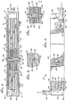
- a charge air cooler 10 in the form of a heat exchanger adapted to fit within an induction manifold 12 of an internal combustion engine.
- the charge air cooler 10 is held within the induction manifold 12 by means of a plurality of mounting bolts 14 in such a way that the heat transfer elements of the charge air cooler 10 are not subjected to substantial mechanical mounting forces.
- the charge air cooler 10 and the induction manifold 12 are intended for use with an internal combustion engine (not shown) which is supplied with compressed ambient air from a supercharger, turbocharger, or the like (also not shown).
- the induction manifold 12 forms a portion of the flow path through which the compressed air, commonly referred to as charge air, passes on its way to the engine combustion chamber or chambers and the charge air cooler is provided for reducing the temperature of the charge air prior to induction into the engine. This reduction in temperature of the charge air advantageously increases the charge air density and decreases the overall heat load on the engine for the purpose of increasing overall engine performance and economy.
- FIG. 1 A typical induction manifold 12 with which the charge air cooler of this invention can be used is illustrated in detail in Figures 1 and 2.
- the manifold 12 comprises an upper, manifold cover section 16 and a lower, manifold body section 18 which cooperate to define a manifold chamber 20 in which the charge air cooler 10 is mounted.
- the upper manifold section 16 is connected to a charge air supply conduit 22 through which in use charge air arrives from a turbocharger or the like to flow downwardly into the manifold chamber 20 and pass through the charge air cooler 10 prior to discharge to the engine combustion chamber or chambers through a plurality of individual outlet conduits 24.
- the upper and lower manifold sections 16 and 18 respectively include mating flanges 26 and 28 through which a plurality of connecting bolts 30 are fastened to connect the manifold sections securely together.
- a sealing gasket 32 can be interposed between the flanges 26 and 28 to prevent fluid leakage.
- the charge air cooler 10 comprises a heat exchanger structure the size and shape of which is such as to fit closely into the lower manifold section 18 of the intake manifold 12 so that the charge air passing downwardly through the manifold is substantially prevented from bypassing the charge air cooler but is constrained to flow through an air flow path within the charge air cooler in heat exchange relation with a coolant which is circulated through a coolant fluid flow path within the charge air cooler.
- the charge air cooler shown in the drawings is a so-called plate-and-fin heat exchanger having a heat exchanger core comprising a stacked array of lightweight plates constituting the heat transfer elements with a plurality of lightweight divider fins extending between them.
- the cooler heat exchanger core has a plurality of first fin elements 34 each formed from a lightweight material having relatively high heat conductive properties, such as thin copper sheet shaped to have a generally corrugated cross section defining an extended heat transfer surface area.
- a plurality of second fin elements 36 are also formed from a lightweight material having high heat conductive properties, such as thin copper sheet shaped to have a generally corrugated cross section also defining extended surface heat transfer areas.
- the plate fin elements 34 are oriented with their corrugations extending orthogonally with respect to those of the fin elements 36, and stacked alternately therewith, the fin elements 32 and 36 being separated from each other in the stack by a plurality of thin, lightweight divider plates 38 of a heat conductive material such as copper.
- the entire stack, comprising the fin elements 34 and 36 and the divider plates 38 is sandwiched between a pair of protective side plates 40 which are also formed from a heat conductive material, such as copper, and which advantageously may have a lightweight and thin construction generally corresponding to that of the divider plates 38.
- the fin elements 34 are arranged with their corrugations extending generally vertically so that these elements 34 cooperate with the divider plates 38 and the side plates 40 to define a plurality of vertically extending, relatively small passages 42.
- the flow openings 42 together constitute a first flow path, for the charge air through the heat exchanger core when the charge air cooler 10 is mounted within the induction manifold 12.
- the second set of fin elements 36 are arranged with their corrugatio.s extending horizontally, generally in a longitudinal direction from one end of the heat exchanger core to the other and generally orthogonally of the passages 42 defining the charge air flow path.
- the fin elements 36 of the second set cooperate with the divider plates 38 to define a plurality of longitudinally extending and relatively small passageways 44 which provide a second flow path through the manifold for the passage of the coolant in heat exchange relation with the charge air.
- the upper and lower longitudinal margins of the fin elements 36 of the second set are bounded by longitudinally extending header bars 46 positioned between adjacent divider plates 38.
- Coolant is supplied to one end of the charge air cooler 10 for flow through the longitudinal passageways 44 and discharge therefrom at the opposite end of the cooler. More particularly, a header tank 50 is supported at one end of the cooler 10 by the side plates 40 and the header bars 46 to provide a plenum chamber 52 in open communication with the adjacent ends of the longitudinal passageways 44.
- the coolant which may be a liquid coolant pumped from the radiator of an engine cooling system of known type, is directed into this header tank 50 through an inlet tube 54 the size and shape of which is such that it is received closely in an opening 56 in the end of the lower, manifold body section 18 when the charge air cooler is mounted within the manifold. If desired, the inlet tube 54 can be sealed in the opening 56 by use of an appropriate gasket (not shown) or other sealer.
- the coolant discharged from the longitudinal flow openings 44 is collected within a second plenum chamber 58 constituted by a header tank 60 supported at the other ends of the side plates 40 and the header bars 46 from the tank 50.
- the collected coolant is then guided away from the cooler 10 for return through an outlet tube 62 to the radiator (not shown) of an engine cooling system.
- This outlet tube 62 is shaped to fit through an opening 64 in the upper manifold' cover section 16, and the outlet tube 62 can be sealed in the opening 64 by the use of an appropriate gasket (not shown).
- the component parts of the charge air cooler 10 as described above are all formed from a suitable material, such as copper, aluminium, or the like, having an acceptably high thermal conductivity for efficient transfer of heat between the charge air and the coolant. Moreover, the component parts are all selected from a material compatible with manufacturing techniques for joining them together to form a composite assembly. For example, it is convenient to make the whole of the cooler 10 from copper components and to subject these components to a brazing process to join them together to form a structure which can be mounted as a unit into the air intake manifold 12.
- the charge air cooler 10 also includes structural members which cooperate with the mounting bolts 14 to permit the cooler 10 to be retained in the manifold 12. These structural members are advantageously small and compact in size, yet function to support the mechanical forces applied by the bolts 14 so that these forces are substantially prevented from acting on the fin elements 34 or 36, on the divider plates 37, or on the side plates 40. All of these components can thus be structurally lightweight in material and thickness. These structural members are rigid sleeves 66 which extend transversely through the heat exchanger core and are formed from a material compatible for connection to the other components of the core, such as by brazing, during manufacture of the charge air cooler 10.
- Each mounting sleeve 66 extends transversely through a passage defined in the core by an aligned set of openings 68, 69, 70 and 71 formed respectively in the side plates 40, the fin elements 34 of the first set, the divider plates 38, and the fin elements 36 of the second set.
- Each mounting sleeve 66 is solidly anchored to the side plates 40, such as by brazing.
- each sleeve is anchored to the divider plates 38 by a plurality of annular sealing rings 72 carried about the sleeve at axial positions corresponding with the fin elements 36 of the second set and projecting radially outwardly therefrom between the adjacent pair of divider plates 38.
- sealing rings 72 are secured to the sleeve 66 and the divider plates 38 in a leak free manner, such as by brazing, to prevent leakage of the fluids where the mounting sleeve through the places 38.
- the openings 71 in the fin elements 36 of the. second set are enlarged with respect to the openings 70 in the divider plates 38 to permit a free flow of coolant about the sealing rings 72 as it passes toward the outlet end of the heat exchanger core.
- the charge air cooler 10 fits into the lower, manifold body section 18 of the manifold 12, and the mounting bolts 14 are passed through the manifold body section 18 and the charge air cooler 10 to secure the cooler in place.
- the manifold body section 18 is provided with sets of aligned bolt-receiving holes 74 and 76 formed in the opposite walls 78 and 80 thereof at longitudinal positions corresponding to the required position of each mounting sleeve 66.
- Each of the mounting bolts 14 is received through the associated hole 74 in the wall 78, through the bore 82 of the mounting sleeve 66, and through the aligned hole 76 in the opposite wall 80.
- the holes 76 in the wall 80 are threaded to permit the mounting bolts 14 to be screwed directly to the manifold wall 80.
- Flat washers 84 and lock washers 86 are provided to prevent the bolts 14 from working loose during use.
- the mounting bolts 14 are tightened by turning them within the threaded holes 76 sufficiently to draw the opposite walls 78 and 80 of the lower manifold section 18 into bearing engagement with the charge air cooler 10 and thereby securely mount the charge air cooler 10 in the induction manifold.
- the mounting sleeves 66 have a length at least as great as the width of the cooler and preferably are slightly longer than this so as to project slightly beyond the opposite exterior surfaces of the heat exchanger core as constituted by the side plates 40.
- the mounting arrangement illustrated in Figures 1 to 4 is particularly advantageous when the manifold wall 80 is disposed adjacent the engine and is thus substantially inaccessible when the manifold 12 is mounted on the engine.
- the mounting sleeves 66 permit the use of elongated mounting bolts in the form of set screws 14 which pass through the accessible, outboard wall 78 and entirely through the charge air cooler for threaded fastening into the inboard wall 80 without requiring additional bolts or nuts at the inboard side of the manifold.
- the charge air cooler may therefore be mounted to and/or removed from the manifold 12 both quickly and easily whilst the intake manifold is still in place on the engine.
- FIG. 5 Part of a second embodiment is illustrated by way of example in Figure 5, in which those components which are identical to or fulfil the same function as corresponding components in the embodiment of Figures 1 to 4 are designated by the same reference numerals.
- one or more mounting sleeves 166 are carried by a charge air cooler 10 having a heat exchanger core in the form of a stack of fin elements 34 and 36, divider plates 38, and side plates 40.
- This charge air cooler is shaped and dimensioned to be received into manifold 12 like that illustrated in Figure 1, in which a lower manifold section 18 has opposite side walls 178 and 180 with bolt-receiving holes 174 and 176 formed respectively therein.
- the bore 182 of the mounting sleeve 166 is internally threaded for reception of a pair of mounting bolts 114 and 115 into the opposite ends thereof.
- the bolt 114 is received through the hole 174 in the manifold wall 178 and is screwed directly into the mounting sleeve 166.
- the other bolt 115 is received through the hole 176 in the manifold wall 180 and is screwed directly into the opposite end of the mounting sleeve 166. Both bolts 114 and 115 are tightened to draw the manifold walls 178 and 180 into bearing engagement with the opposite ends of the sleeve 166, which again project beyond the side plates 40, whereby securely to anchor the charge air cooler within the manifold.
- the charge air cooler of this invention thus can be mounted quickly and easily into an induction manifold, and the heat transfer components of the cooler are substantially isolated from mechanical forces due to its mounting. Moreover, if desired, mounting of the cooler can be accomplished from one side of the manifold by using elongate set screws which pass entirely through the cooler and screw into the opposite side of the manifold.
Landscapes
- Engineering & Computer Science (AREA)
- Physics & Mathematics (AREA)
- Thermal Sciences (AREA)
- Mechanical Engineering (AREA)
- General Engineering & Computer Science (AREA)
- Chemical & Material Sciences (AREA)
- Combustion & Propulsion (AREA)
- Heat-Exchange Devices With Radiators And Conduit Assemblies (AREA)
Applications Claiming Priority (2)
| Application Number | Priority Date | Filing Date | Title |
|---|---|---|---|
| US318937 | 1981-11-06 | ||
| US06/318,937 US4436145A (en) | 1981-11-06 | 1981-11-06 | Charge air cooler mounting arrangement |
Publications (2)
| Publication Number | Publication Date |
|---|---|
| EP0079217A2 true EP0079217A2 (de) | 1983-05-18 |
| EP0079217A3 EP0079217A3 (de) | 1984-05-23 |
Family
ID=23240196
Family Applications (1)
| Application Number | Title | Priority Date | Filing Date |
|---|---|---|---|
| EP82305903A Withdrawn EP0079217A3 (de) | 1981-11-06 | 1982-11-05 | Ladeluftkühler |
Country Status (2)
| Country | Link |
|---|---|
| US (1) | US4436145A (de) |
| EP (1) | EP0079217A3 (de) |
Cited By (7)
| Publication number | Priority date | Publication date | Assignee | Title |
|---|---|---|---|---|
| DE19927607A1 (de) * | 1999-06-17 | 2000-12-21 | Behr Gmbh & Co | Ladeluftkühler mit einem Kühlmitteleintritt sowie einem Kühlmittelaustritt |
| DE10302708A1 (de) * | 2003-01-23 | 2004-07-29 | Behr Gmbh & Co. Kg | Vorrichtung zum Austausch von Wärme |
| WO2010026293A1 (en) * | 2008-09-03 | 2010-03-11 | Wärtsilä Finland Oy | Intercooler arrangement for a super-charged piston engine |
| CN102695936A (zh) * | 2009-09-16 | 2012-09-26 | 摩丁制造公司 | 包括进口槽和出口槽的堆叠/条状板进气冷却器 |
| US20140216385A1 (en) * | 2013-02-07 | 2014-08-07 | Mahle International Gmbh | Fresh air supply device of an international combustion engine |
| DE102011123015B3 (de) | 2011-05-05 | 2021-10-28 | MAHLE Behr GmbH & Co. KG | Ladeluftkanal für einen Verbrennungsmotor |
| DE102011100629B4 (de) | 2011-05-05 | 2022-05-19 | MAHLE Behr GmbH & Co. KG | Ladeluftkanal für einen Verbrennungsmotor |
Families Citing this family (42)
| Publication number | Priority date | Publication date | Assignee | Title |
|---|---|---|---|---|
| US4474162A (en) * | 1983-03-01 | 1984-10-02 | The Garrett Corporation | Charge air cooler mounting arrangement |
| US4796695A (en) * | 1983-06-30 | 1989-01-10 | Phillips Petroleum Company | Tube supports |
| US4653574A (en) * | 1983-08-04 | 1987-03-31 | L. B. White Company, Inc. | Air to air heat exchanger |
| US4565177A (en) * | 1983-09-09 | 1986-01-21 | Cummins Engine Company, Inc. | Unitized cross tie aftercooler assembly |
| FR2583864B1 (fr) * | 1985-06-25 | 1989-04-07 | Inst Francais Du Petrole | Dispositif d'echange thermique du type echangeur a plaques perforees presentant une etancheite amelioree. |
| FR2623895B1 (fr) * | 1987-11-27 | 1990-07-06 | Valeo | Echangeur de chaleur comportant un faisceau de tubes a ailettes et une enveloppe entourant ledit faisceau |
| US4823868A (en) * | 1988-05-26 | 1989-04-25 | Deere & Company | Intercooler and method of assembling the same |
| US4967716A (en) * | 1989-04-27 | 1990-11-06 | Deere & Company | Internal combustion engine with integral intercooler |
| US5316079A (en) * | 1993-02-12 | 1994-05-31 | Paccar Inc | Integrated heat exchanger |
| US6311676B1 (en) * | 1999-10-28 | 2001-11-06 | Daimlerchrysler Corporation | Intercooler arrangement for a motor vehicle engine |
| JP4512873B2 (ja) * | 2001-04-10 | 2010-07-28 | 本田技研工業株式会社 | インタークーラ |
| DE10136861A1 (de) * | 2001-07-27 | 2003-02-20 | Modine Mfg Co | Luftgekühlter Ladeluftkühler |
| DE10147555B4 (de) * | 2001-09-26 | 2014-01-30 | Behr Gmbh & Co. Kg | Vorrichtung zum Befestigen eines Abgas-Wärmeübertragers |
| DE10312032A1 (de) * | 2003-03-18 | 2004-09-30 | Behr Gmbh & Co. Kg | Sammelkasten, Wärmeübertrager und Verfahren zur Herstellung eines Sammelkastens |
| WO2005040708A1 (de) * | 2003-10-20 | 2005-05-06 | Behr Gmbh & Co. Kg | Wärmetauscher |
| DE10359806A1 (de) * | 2003-12-19 | 2005-07-14 | Modine Manufacturing Co., Racine | Wärmeübertrager mit flachen Rohren und flaches Wärmeübertragerrohr |
| NL1027948C2 (nl) * | 2005-01-04 | 2006-07-05 | Eindhovense Radiateurenfabriek | Koelinrichting. |
| US20080251242A1 (en) * | 2005-10-20 | 2008-10-16 | Behr Gmbh & Co. Kg | Heat Exchanger |
| DE102005053924B4 (de) * | 2005-11-11 | 2016-03-31 | Modine Manufacturing Co. | Ladeluftkühler in Plattenbauweise |
| US20090250201A1 (en) * | 2008-04-02 | 2009-10-08 | Grippe Frank M | Heat exchanger having a contoured insert and method of assembling the same |
| CN101589286B (zh) * | 2007-01-23 | 2011-09-28 | 摩丁制造公司 | 热交换器和方法 |
| US8424592B2 (en) * | 2007-01-23 | 2013-04-23 | Modine Manufacturing Company | Heat exchanger having convoluted fin end and method of assembling the same |
| ATE479015T1 (de) * | 2007-07-11 | 2010-09-15 | Joaeo De Deus & Filhos S A | Wärmetauscheranordnung |
| DE102009038592A1 (de) * | 2009-08-26 | 2011-03-10 | Behr Gmbh & Co. Kg | Gaskühler für einen Verbrennungsmotor |
| DE102009050258B3 (de) * | 2009-10-21 | 2010-11-18 | Mann + Hummel Gmbh | Saugrohr einer Brennkraftmaschine und Kühlfluidladeluftkühler |
| DE102009055715A1 (de) * | 2009-11-26 | 2011-06-01 | Behr Gmbh & Co. Kg | Saugrohr mit integriertem Ladeluftkühler |
| DE102010037152B4 (de) * | 2010-08-25 | 2022-08-25 | Gea Wtt Gmbh | Plattenwärmetauscher in abgedichteter Ausführung |
| DE202011005693U1 (de) * | 2011-04-28 | 2011-09-26 | Behr Gmbh & Co. Kg | Schichtwärmeübertager |
| DE102011080474A1 (de) * | 2011-08-05 | 2013-02-07 | Behr Gmbh & Co. Kg | Wärmetauscheranordnung |
| DE102012212867A1 (de) * | 2012-07-23 | 2014-01-23 | Behr Gmbh & Co. Kg | System zur Ladeluftkühlung und zugehöriges Verfahren zur Bereitstellung einer Ladeluftkühlung für einen Verbrennungsmotor |
| DE102014000450B4 (de) * | 2013-02-18 | 2016-02-18 | Modine Manufacturing Company | Einlasskrümmer mit Ladeluftkühler |
| US9038610B2 (en) * | 2013-02-18 | 2015-05-26 | Modine Manufacturing Company | Charge air cooler, and intake manifold including the same |
| US9109500B2 (en) | 2013-07-19 | 2015-08-18 | Ford Global Technologies, Llc | Charge air cooler housing water trap |
| USD726784S1 (en) | 2013-08-06 | 2015-04-14 | General Electric Company | Exhaust gas recirculation cooler |
| JP2015144196A (ja) * | 2014-01-31 | 2015-08-06 | 三桜工業株式会社 | 冷却装置及び冷却装置の製造方法 |
| DE112015002074T5 (de) | 2014-04-29 | 2017-02-23 | Dana Canada Corporation | Ladeluftkühler mit mehrteiligem Kunststoffgehäuse |
| DE112017000586T5 (de) * | 2016-02-01 | 2018-12-13 | Dana Canada Corporation | Strukturell integraler wärmetauscher in einem kunststoffgehäuse |
| US10151231B2 (en) * | 2016-05-19 | 2018-12-11 | Hanon Systems | Manifold integrated intercooler with structural core |
| EP3330657B1 (de) | 2016-12-01 | 2020-10-28 | Modine Manufacturing Company | Luftrippe für einen wärmetauscher und verfahren zur herstellung davon |
| US10882378B2 (en) * | 2017-08-18 | 2021-01-05 | Zhejiang CFMOTO Power Co., Ltd. | ATV air heat exchanger with mounting structure and linkage |
| DE102019121494A1 (de) * | 2019-08-09 | 2021-02-11 | Mann+Hummel Gmbh | Wärmetauscheranordnung, Verfahren zur Herstellung einer Wärmetauscheranordnung und Brennkraftmaschine mit Wärmetauscheranordnung |
| CN112412614B (zh) * | 2020-11-18 | 2022-02-08 | 浙江银轮机械股份有限公司 | 芯片、芯体及中冷器 |
Family Cites Families (33)
| Publication number | Priority date | Publication date | Assignee | Title |
|---|---|---|---|---|
| US1108494A (en) | 1914-08-25 | Electrolytic Products Company | Radiator and radiator-sections for automobiles, motor-cars, and the like. | |
| US621693A (en) | 1899-03-21 | George w | ||
| US1250187A (en) | 1916-04-24 | 1917-12-18 | Frank Jutrasch | Cooling-radiator. |
| US1374394A (en) | 1919-02-15 | 1921-04-12 | Oscar A Ross | Combined automobile fender and radiator-protector |
| FR507163A (fr) | 1919-04-02 | 1920-09-07 | Goudard Et Mennesson M | Perfectionnements apportés aux radiateurs et notamment à ceux pour moteurs à explosions |
| US1500560A (en) | 1921-04-09 | 1924-07-08 | Albert E L Henderson | Radiator-tube joint |
| FR635300A (fr) | 1926-05-19 | 1928-03-12 | Réchauffeurs d'air composés de groupes d'éléments ou poches | |
| US1692391A (en) | 1927-01-06 | 1928-11-20 | Stancliffe Cecil Wheatley | Heat-transfer apparatus |
| US1727124A (en) | 1928-04-10 | 1929-09-03 | Foster Wheeler Corp | Plate air-heater construction |
| US1856924A (en) | 1929-08-07 | 1932-05-03 | Modine Mfg Co | Air heating unit |
| US2308119A (en) | 1940-02-23 | 1943-01-12 | Modine Mfg Co | Radiator construction |
| GB548270A (en) * | 1941-03-31 | 1942-10-02 | Thomas Shelley | Improvements in or relating to supercharged internal-combustion engines |
| US2348020A (en) | 1941-04-17 | 1944-05-02 | Gen Electric | Heat exchanger |
| CH222623A (de) | 1941-07-23 | 1942-07-31 | Sulzer Ag | Querstrom-Plattenwärmeaustauscher. |
| US2611586A (en) | 1948-01-17 | 1952-09-23 | Joy Mfg Co | Heat exchanger |
| BE493098A (de) | 1949-01-14 | |||
| FR1035981A (fr) | 1952-04-16 | 1953-09-02 | Svenska Flaektfabriken Ab | échangeur de température |
| US2863645A (en) | 1953-11-16 | 1958-12-09 | Modine Mfg Co | Heat exchanger mounting |
| US2942856A (en) | 1959-01-13 | 1960-06-28 | Kenneth E Woodward | Fluid-cooled electrical module assembly |
| US3091228A (en) * | 1961-04-17 | 1963-05-28 | Caterpillar Tractor Co | Engine with turbocharger and aftercooling |
| US3137887A (en) * | 1962-06-15 | 1964-06-23 | Republic Aviat Corp | Bushing |
| US3334399A (en) | 1962-12-31 | 1967-08-08 | Stewart Warner Corp | Brazed laminated construction and method of fabrication thereof |
| US3196937A (en) | 1963-09-24 | 1965-07-27 | Rosenblads Patenter Ab | Two unit plate heat exchanger with end supports |
| US3444926A (en) | 1967-11-28 | 1969-05-20 | Rosenblads Patenter Ab | Arrangement in heat exchangers of the plate type |
| DE1913226B1 (de) | 1969-03-15 | 1970-08-27 | Krupp Gmbh | Aus Hohlscheiben bestehender Waermeaustauscher |
| US3791326A (en) | 1970-07-07 | 1974-02-12 | Dunham Bush Inc | Method of forming a modular header for a tube within a tube heat exchanger |
| DE2304883A1 (de) | 1973-02-01 | 1974-08-08 | Buderus Eisenwerk | Halterung fuer einen heizkoerper |
| US3829945A (en) | 1973-07-11 | 1974-08-20 | Motoren Werke Mannheim Ag | Method of producing a heat exchanger |
| US3881455A (en) | 1973-10-31 | 1975-05-06 | Allis Chalmers | Aftercooler for internal combustion engine |
| US4191148A (en) | 1977-06-30 | 1980-03-04 | Cummins Engine Company, Inc. | Aftercooler assembly for internal combustion engine |
| US4269158A (en) * | 1978-07-06 | 1981-05-26 | Allis-Chalmers Corporation | Intercooler for internal combustion engine |
| US4303052A (en) | 1980-03-24 | 1981-12-01 | The Garrett Corporation | Charge air cooler mounting arrangement |
| US4330030A (en) | 1980-04-21 | 1982-05-18 | Deere & Company | Heat exchanger isolation mounting arrangement |
-
1981
- 1981-11-06 US US06/318,937 patent/US4436145A/en not_active Expired - Fee Related
-
1982
- 1982-11-05 EP EP82305903A patent/EP0079217A3/de not_active Withdrawn
Cited By (12)
| Publication number | Priority date | Publication date | Assignee | Title |
|---|---|---|---|---|
| DE19927607A1 (de) * | 1999-06-17 | 2000-12-21 | Behr Gmbh & Co | Ladeluftkühler mit einem Kühlmitteleintritt sowie einem Kühlmittelaustritt |
| DE10302708A1 (de) * | 2003-01-23 | 2004-07-29 | Behr Gmbh & Co. Kg | Vorrichtung zum Austausch von Wärme |
| WO2010026293A1 (en) * | 2008-09-03 | 2010-03-11 | Wärtsilä Finland Oy | Intercooler arrangement for a super-charged piston engine |
| CN102695936A (zh) * | 2009-09-16 | 2012-09-26 | 摩丁制造公司 | 包括进口槽和出口槽的堆叠/条状板进气冷却器 |
| CN102695936B (zh) * | 2009-09-16 | 2015-01-21 | 摩丁制造公司 | 包括进口槽和出口槽的堆叠/条状板进气冷却器 |
| DE102011123015B3 (de) | 2011-05-05 | 2021-10-28 | MAHLE Behr GmbH & Co. KG | Ladeluftkanal für einen Verbrennungsmotor |
| DE102011100629B4 (de) | 2011-05-05 | 2022-05-19 | MAHLE Behr GmbH & Co. KG | Ladeluftkanal für einen Verbrennungsmotor |
| US20140216385A1 (en) * | 2013-02-07 | 2014-08-07 | Mahle International Gmbh | Fresh air supply device of an international combustion engine |
| EP2765286A1 (de) * | 2013-02-07 | 2014-08-13 | Mahle International GmbH | Frischluftversorgungseinrichtung einer Brennkraftmaschine |
| CN103982345A (zh) * | 2013-02-07 | 2014-08-13 | 马勒国际有限公司 | 内燃机的新鲜空气供给装置 |
| CN103982345B (zh) * | 2013-02-07 | 2018-07-24 | 马勒国际有限公司 | 内燃机的新鲜空气供给装置 |
| US10422273B2 (en) | 2013-02-07 | 2019-09-24 | Mahle International Gmbh | Fresh air supply device of an international combustion engine |
Also Published As
| Publication number | Publication date |
|---|---|
| US4436145A (en) | 1984-03-13 |
| EP0079217A3 (de) | 1984-05-23 |
Similar Documents
| Publication | Publication Date | Title |
|---|---|---|
| US4436145A (en) | Charge air cooler mounting arrangement | |
| US4474162A (en) | Charge air cooler mounting arrangement | |
| US4303052A (en) | Charge air cooler mounting arrangement | |
| US6755158B2 (en) | Vehicle charge air cooler with a pre-cooler | |
| US4565177A (en) | Unitized cross tie aftercooler assembly | |
| KR940007191B1 (ko) | 차량의 열교환기 모듈 | |
| US6886624B2 (en) | Compact cooling system | |
| US5316079A (en) | Integrated heat exchanger | |
| CA1138279A (en) | Engine with integral mounted egr cooler | |
| US4269158A (en) | Intercooler for internal combustion engine | |
| US20060207757A1 (en) | Heat exchanger exhaust gas recirculation cooler | |
| US4191148A (en) | Aftercooler assembly for internal combustion engine | |
| EP0167807B1 (de) | Verdichtungsanlage für Wärmekraftmaschinen | |
| CA2084357A1 (en) | Mixed heat exchanger for air intake circuits in internal combustion engines | |
| US9228479B2 (en) | Marine diesel engines | |
| US4104999A (en) | After-cooler accessory unit for internal combustion engine having a carburetor | |
| US5383439A (en) | Air inlet aftercooler mounting and sealing system | |
| US4424778A (en) | Coupler for use in an oil cooling system | |
| GB2062749A (en) | Internal Combustion Engine With EGR Cooler | |
| US20100126704A1 (en) | Heat Exchanger with Direct Flow Path Modules | |
| US20260036076A1 (en) | Aftercooler for internal combustion engine | |
| US20100059010A1 (en) | Heat Insulator For An Intake Manifold Of An Air-Cooled Charge Air Cooler | |
| CN112459895B (zh) | 一种中冷器 | |
| RU219266U1 (ru) | Охладитель наддувочного воздуха | |
| CN114934840B (zh) | 中冷器芯体及中冷器总成 |
Legal Events
| Date | Code | Title | Description |
|---|---|---|---|
| PUAI | Public reference made under article 153(3) epc to a published international application that has entered the european phase |
Free format text: ORIGINAL CODE: 0009012 |
|
| AK | Designated contracting states |
Designated state(s): DE FR GB IT NL SE |
|
| PUAL | Search report despatched |
Free format text: ORIGINAL CODE: 0009013 |
|
| AK | Designated contracting states |
Designated state(s): DE FR GB IT NL SE |
|
| 17P | Request for examination filed |
Effective date: 19841107 |
|
| STAA | Information on the status of an ep patent application or granted ep patent |
Free format text: STATUS: THE APPLICATION HAS BEEN WITHDRAWN |
|
| 18W | Application withdrawn |
Withdrawal date: 19870727 |
|
| RIN1 | Information on inventor provided before grant (corrected) |
Inventor name: HIRSCH, SELWYN ROY Inventor name: MANFREDO, JOSEPH H. |