EP0079246B1 - Cristallisateur - Google Patents
Cristallisateur Download PDFInfo
- Publication number
- EP0079246B1 EP0079246B1 EP82305986A EP82305986A EP0079246B1 EP 0079246 B1 EP0079246 B1 EP 0079246B1 EP 82305986 A EP82305986 A EP 82305986A EP 82305986 A EP82305986 A EP 82305986A EP 0079246 B1 EP0079246 B1 EP 0079246B1
- Authority
- EP
- European Patent Office
- Prior art keywords
- crystallizer
- mixing tank
- zone
- pipe
- crystals
- Prior art date
- Legal status (The legal status is an assumption and is not a legal conclusion. Google has not performed a legal analysis and makes no representation as to the accuracy of the status listed.)
- Expired
Links
- 239000013078 crystal Substances 0.000 claims description 53
- 238000002156 mixing Methods 0.000 claims description 36
- 239000007788 liquid Substances 0.000 claims description 18
- 150000002500 ions Chemical class 0.000 claims description 7
- 239000002904 solvent Substances 0.000 claims description 7
- 238000000605 extraction Methods 0.000 claims description 4
- 239000000243 solution Substances 0.000 description 48
- 239000003960 organic solvent Substances 0.000 description 36
- 150000003839 salts Chemical class 0.000 description 14
- 229910021645 metal ion Inorganic materials 0.000 description 10
- 239000007864 aqueous solution Substances 0.000 description 8
- 238000001704 evaporation Methods 0.000 description 6
- 230000008020 evaporation Effects 0.000 description 6
- 238000000034 method Methods 0.000 description 6
- -1 Fe3+ ions Chemical class 0.000 description 5
- 239000012074 organic phase Substances 0.000 description 5
- XLYOFNOQVPJJNP-UHFFFAOYSA-N water Substances O XLYOFNOQVPJJNP-UHFFFAOYSA-N 0.000 description 5
- 238000006243 chemical reaction Methods 0.000 description 4
- 238000012986 modification Methods 0.000 description 4
- 230000004048 modification Effects 0.000 description 4
- 238000013019 agitation Methods 0.000 description 3
- 239000008346 aqueous phase Substances 0.000 description 3
- 239000012141 concentrate Substances 0.000 description 3
- 229910000765 intermetallic Inorganic materials 0.000 description 3
- 239000002184 metal Substances 0.000 description 3
- 238000000638 solvent extraction Methods 0.000 description 3
- 229910017665 NH4HF2 Inorganic materials 0.000 description 2
- 239000000470 constituent Substances 0.000 description 2
- 238000013461 design Methods 0.000 description 2
- 230000000694 effects Effects 0.000 description 2
- XTAZYLNFDRKIHJ-UHFFFAOYSA-N n,n-dioctyloctan-1-amine Chemical compound CCCCCCCCN(CCCCCCCC)CCCCCCCC XTAZYLNFDRKIHJ-UHFFFAOYSA-N 0.000 description 2
- 230000001376 precipitating effect Effects 0.000 description 2
- 238000001556 precipitation Methods 0.000 description 2
- 150000004945 aromatic hydrocarbons Chemical class 0.000 description 1
- UNTBPXHCXVWYOI-UHFFFAOYSA-O azanium;oxido(dioxo)vanadium Chemical compound [NH4+].[O-][V](=O)=O UNTBPXHCXVWYOI-UHFFFAOYSA-O 0.000 description 1
- 150000001875 compounds Chemical group 0.000 description 1
- 238000007796 conventional method Methods 0.000 description 1
- 239000002826 coolant Substances 0.000 description 1
- 238000001816 cooling Methods 0.000 description 1
- 238000002425 crystallisation Methods 0.000 description 1
- 230000008025 crystallization Effects 0.000 description 1
- 238000011161 development Methods 0.000 description 1
- 238000010586 diagram Methods 0.000 description 1
- 230000005484 gravity Effects 0.000 description 1
- 239000012188 paraffin wax Substances 0.000 description 1
- 239000002244 precipitate Substances 0.000 description 1
- 238000004062 sedimentation Methods 0.000 description 1
- 238000000926 separation method Methods 0.000 description 1
- 238000003756 stirring Methods 0.000 description 1
- 239000000126 substance Substances 0.000 description 1
- 238000012546 transfer Methods 0.000 description 1
- 238000011282 treatment Methods 0.000 description 1
- 238000007738 vacuum evaporation Methods 0.000 description 1
Images


Classifications
-
- B—PERFORMING OPERATIONS; TRANSPORTING
- B01—PHYSICAL OR CHEMICAL PROCESSES OR APPARATUS IN GENERAL
- B01D—SEPARATION
- B01D9/00—Crystallisation
- B01D9/0036—Crystallisation on to a bed of product crystals; Seeding
-
- B—PERFORMING OPERATIONS; TRANSPORTING
- B01—PHYSICAL OR CHEMICAL PROCESSES OR APPARATUS IN GENERAL
- B01D—SEPARATION
- B01D9/00—Crystallisation
- B01D9/005—Selection of auxiliary, e.g. for control of crystallisation nuclei, of crystal growth, of adherence to walls; Arrangements for introduction thereof
Definitions
- the present invention relates to a crystallizer having a mixing tank in which an organic solvent containing ions of a metal may be mixed with an aqueous separating solution.
- Crystallizers are known for crystallizing a metallic salt from its aqueous solution, by causing the crystals to precipitate on concentrating the solution by evaporation.
- the crystallizer may have multistage pressure reducing zones. Instead, the crystallizer may be arranged to cool the solution, to crystallize a substance having a large variation in solubility with temperature.
- another salt may be added to the solution outside the crystallizer, to decrease the solubility of the required salt.
- crystalliser where a chemical reaction is performed therewithin, which reaction-results in crystals being precipitated out of a solution supplied to the crystallizer.
- One such . reaction is a solvent extraction technique, in which metal ions are extracted into an organic solvent and are then taken out as a salt in a separating solution.
- the separating solution is an aqueous solution in which the solubility of the required metallic salt is small, crystals of the salt tend to precipitate in a mixing tank wherein are mixed the separating solution and the organic solvent, the crystals adhering to the inner wall of the mixing tank, and if a stirrer is provided, on the wings thereof.
- a crystallizer operating on the solvent extraction technique is disclosed in DE-A-22466676, but this crystallizer suffers from the disadvantage that it cannot be operated for long periods of time without servicing. This is because the agitation of the solutions within the mixing tank causes significant precipitation of crystals therewithin, such crystals then adhering to the walls of the mixing tank. Moreover, due to such agitation, the forming crystals are contacted with the organic solvent, which thus becomes consumed uneconomically due to the adhesion thereof to the crystals. Particularly, when operating with complex salts as metal-ammonium fluorides and metal-ammonium sulphates which are hardly soluble in water, these phenomena take place to a significant extent, preventing economic industrial utilization of this design of crystallizer.
- this invention provides a crystallizer comprising a crystallizer body having an upper part and a lower part the cross-section of which narrows from the body upper part down to the lower end of the body lower part, an open topped mixing tank disposed in the upper part to define a mixing zone for solvent containing ions to be crystallized and separating solution, and the lower part serving as a crystal-developing zone for crystals developing in the separating solution, there being a solvent discharge pipe to discharge solvent from the mixing zone, a crystal discharge pipe connected to the lower part, and liquid inlet arranged at or near the lower end of the lower part of the crystallizer body, which crystallizer is characterised by the provision of a pipe within the crystallizer body which pipe descends from the lower region of the open topped mixing tank into the lower part of the crystal-developing zone, and by a separating solution extraction pipe arranged to draw off separating solution from the region of the junction between the upper and lower parts of the crystallizer, and further by the provision of a recirculation system
- the crystallizer of this invention allows a rapid and prompt separation of the organic solvent from the aqueous separating solution, by virtue of the said pipe leading the aqueous solution together with the metal ions away from the mixing tank. Agitation of the developing crystals is performed by the aqueous solution introduced into the inlet at the lower part of the body, so maintaining separate the developing crystals from the organic solvent.
- an organic solvent settling zone outside the mixing tank, to receive and allow settling of organic solvent overflowing from the mixing tank, there being a discharge pipe for organic solvent settling in the settling zone.
- the separating solution extraction pipe allows the discharge of liquid from the crystallizer body for recirculation through the crystallizer. At least a portion of such extracted liquid may be reintroduced through the liquid inlet at the lower end of the lower part of the crystallizer body. By reintroducing the liquid, the crystals settling in the lower part of the crystallizer body may be fluidized, so as to agitate the crystals. Moreover, the temperature of the liquid in the crystallizer may be controlled by appropriate adjustment of the temperature of the liquid being recirculated through said liquid inlet. Another portion of the extracted aqueous solution may be recirculated into the mixing tank itself.
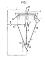
- Organic solvents generally have a lesser density than water, and so the organic solvent is almost completely separated in the open topped mixing tank 4. Any solvent entering the crystal developing zone rises up and overflows therefrom into a settling zone 5, to accumulate above the separating solution in the crystal-developing zone 7, before being discharged through an organic solvent discharge pipe 11. Any organic solvent adhering to the crystals is removed when the crystals are developed in the crystal-developing zone 7, so freeing the crystals from the organic solvent. The separating solution flows upward through the crystal-developing zone 7 while precipitating and developing the crystals.
- the speed at which the separating medium ascends reduces to cause the crystals to precipitate and the crystals so-precipitated are almost perfectly separated in the region of the join between cylindrical part of the crystallizer and the lower conical part thereof-i.e. in the region of the crystal separating zone 13.
- a portion of the separating solution is discharged from the crystallizer through a separating solution discharge pipe 10, though a portion is also drawn off by pump 9, through a ring pipe 17 and separating solution circulation pipe 16, for recirculation to the open topped mixing tank 4 as the separating solution 3.
- the solution can also be sent to a crystal-fluidizing medium inlet 8 provided at the bottom of the main crystallizer body 1 for accelerating the flow rate of the separating solution through the lower part of the crystal-developing zone 7, to prevent the sedimentation of crystals in that lower part.
- a lattice 15 is provided over the inlet 8.
- the crystals are discharged through a crystal discharge pipe 12 provided at an appropriate position in the conical portion of the crystal-developing zone 7, whereafter the crystals can be subjected to further treatments.
- FIG 2 shows a front view of a modification of the apparatus shown in Figure 1.
- This modified embodiment is suitable for use when the solubility of the metallic compound to be crystallized in the aqueous separating solution is relatively large. It is possible to accelerate the precipitation of the crystals by cooling the separating medium coming out of the separating solution circulation pipe 16 by means of a cooler 17, so as to lower the temperature of the separating solution in the crystals developing zone 7.
- the other parts of the apparatus are the same as shown in Figure 1, and will not be described again.
- FIG 3 Another modification of the apparatus is shown in Figure 3, where a heater 17 is provided to heat the separating medium leaving the separating solution circulation pipe 16, so as to prevent the crystals precipitating too much in the mixing zone 4 and in the descending pipe.6.
- a heater 17 is provided to heat the separating medium leaving the separating solution circulation pipe 16, so as to prevent the crystals precipitating too much in the mixing zone 4 and in the descending pipe.6.
- Such an arrangement is suitable for a case where the solubility of the metallic compound to be crystallized is relatively small, unlike the case of Figure 2.
- the other parts of the apparatus are the same as shown in Figure 1, and will not be described again.
- the cooler or the heater 17 may be cooled or heated respectively by using a coolant, or steam 18.
- a coolant or steam 18.
- metal ions extracted into an organic solvent are transferred into an aqueous separating solution which contains a constituent capable of forming a barely-soluble salt with said metal ions for the crystallization thereof.
- the crystals so-produced are uniform, and the loss of organic solvent due to the adhesion thereof to the crystals is small.
- the apparatus can be operated quite economically.
- Fe 3+ ions in the organic phase were transferred to the aqueous phase forming the precipitates of a complex salt, (NH 4 ) 3 FeF 6 , according to the reaction: where R ⁇ H represents an extractant in the organic solvent, and R 3 Fe represents Fe 3+ ions extracted in the organic solvent.
- the crystals obtained adhered on the wall of the mixing tank to a thickness of about 30 mm and on the wings of the stirrer to such an extent that the wings of the turbine could not be seen perfectly after 3 hours' operation. Moreover, the Fe 3+ ions in the organic solvent could not be transferred to the aqueous phase after 5 hours' operation.
- the sizes of the crystals obtained were in the range of 2 to 10 ⁇ .
- the crystals obtained by the apparatus of the present invention had a transparency much higher than that of the crystals obtained by the conventional mixer-settler type apparatus, so proving that the amount of organic solvent adhering on the crystals was very small as compared to the case of the conventional method.
- the crystallizer of this invention it is possible to use an aqueous solution, in which the solubility of the metallic salt concerned is small, as a separating solution, the metal ions in an organic solvent being transferred thereto. Therefore, it is possible to obtain the crystals with no need to concentrate the separating solution by evaporation.
Landscapes
- Chemical & Material Sciences (AREA)
- Crystallography & Structural Chemistry (AREA)
- Chemical Kinetics & Catalysis (AREA)
- Extraction Or Liquid Replacement (AREA)
- Organic Low-Molecular-Weight Compounds And Preparation Thereof (AREA)
- Manufacture And Refinement Of Metals (AREA)
- Light Guides In General And Applications Therefor (AREA)
- Electric Cable Installation (AREA)
Claims (7)
Applications Claiming Priority (2)
| Application Number | Priority Date | Filing Date | Title |
|---|---|---|---|
| JP56179664A JPS5882208A (ja) | 1981-11-11 | 1981-11-11 | 巻付式自己支持型光ケ−ブルの架設方法 |
| JP179644/81 | 1981-11-11 |
Publications (3)
| Publication Number | Publication Date |
|---|---|
| EP0079246A2 EP0079246A2 (fr) | 1983-05-18 |
| EP0079246A3 EP0079246A3 (en) | 1985-11-06 |
| EP0079246B1 true EP0079246B1 (fr) | 1989-01-25 |
Family
ID=16069713
Family Applications (1)
| Application Number | Title | Priority Date | Filing Date |
|---|---|---|---|
| EP82305986A Expired EP0079246B1 (fr) | 1981-11-11 | 1982-11-10 | Cristallisateur |
Country Status (6)
| Country | Link |
|---|---|
| US (1) | US4678646A (fr) |
| EP (1) | EP0079246B1 (fr) |
| JP (1) | JPS5882208A (fr) |
| AU (1) | AU559162B2 (fr) |
| CA (1) | CA1213512A (fr) |
| FI (1) | FI73599C (fr) |
Families Citing this family (16)
| Publication number | Priority date | Publication date | Assignee | Title |
|---|---|---|---|---|
| US4830836A (en) * | 1984-03-30 | 1989-05-16 | Kawasaki Steel Corporation | Metal stripping system and an operation process therefor |
| EP0157562B1 (fr) * | 1984-03-30 | 1989-04-05 | Kawasaki Steel Corporation | Appareil de cristallisation pour la séparation des métaux |
| US4978509A (en) * | 1986-11-18 | 1990-12-18 | The United States Of America As Represented By The United States Department Of Energy | Lamella settler crystallizer |
| US4832442A (en) * | 1987-07-17 | 1989-05-23 | United Ropeworks (U.S.A.) Inc. | Method and apparatus for aerial installation of fiber optic cables |
| US4900157A (en) * | 1988-05-27 | 1990-02-13 | Halliburton Company | Blender system with concentrator |
| US4850701A (en) * | 1988-05-27 | 1989-07-25 | Halliburton Company | Skid-mounted self-leveling mixer apparatus |
| DE3933136A1 (de) * | 1989-10-04 | 1991-04-18 | Krupp Buckau Maschinenbau Gmbh | Verfahren und vorrichtung zum schleudern eines hochviskosen schleudergutes |
| US4960266A (en) * | 1989-12-11 | 1990-10-02 | Siecor Corporation | Aerial cable installation method |
| US4974273A (en) * | 1989-12-27 | 1990-12-04 | Buttermore Edward A | Dart tool |
| US5068092A (en) * | 1990-05-21 | 1991-11-26 | Akzo N.V. | Crystallizer, process and apparatus for producing sodium chloride crystals |
| FR2669556B1 (fr) * | 1990-11-27 | 1993-01-15 | Inst Francais Du Petrole | Dispositif d'agitation et de maintien en suspension des particules d'un ecoulement polyphasique. |
| US7790840B2 (en) * | 2006-05-24 | 2010-09-07 | Eastman Chemical Company | Crystallizing conveyor |
| US7638596B2 (en) * | 2006-05-24 | 2009-12-29 | Eastman Chemical Company | Crystallizer temperature control via jacketing/insulation |
| US7638593B2 (en) * | 2006-05-24 | 2009-12-29 | Eastman Chemical Company | Crystallizer temperature control via fluid control |
| CN103331028B (zh) * | 2013-06-28 | 2015-06-03 | 湖南省湘衡盐化有限责任公司 | 一种制盐蒸发罐盐腿装置 |
| CN109239879B (zh) * | 2018-11-23 | 2020-12-15 | 嘉兴英智杰自动化设备有限公司 | 一种海底除盐覆盖光缆敷设接线盒 |
Family Cites Families (9)
| Publication number | Priority date | Publication date | Assignee | Title |
|---|---|---|---|---|
| US2435898A (en) * | 1943-01-29 | 1948-02-10 | Fuel Refining Corp | Production of ammonium sulphate |
| US2664349A (en) * | 1948-08-07 | 1953-12-29 | Electro Chimie Metal | Method of precipitating solid particles from a suspension of the particles in a liquor |
| US2685499A (en) * | 1950-12-21 | 1954-08-03 | Eastman Kodak Co | Method of proeparing blanc fixe |
| DE1249820B (fr) * | 1963-10-31 | |||
| FR1475801A (fr) * | 1966-02-15 | 1967-04-07 | Air Liquide | Procédé de préparation continue de substances cristallines |
| GB1199253A (en) * | 1966-08-23 | 1970-07-22 | Struthers Scientific Int Corp | Crystallizer |
| US3627496A (en) * | 1968-07-29 | 1971-12-14 | Kerr Mc Gee Chem Corp | Impingement plate for crystallizer |
| JPS5544644B2 (fr) * | 1971-09-23 | 1980-11-13 | ||
| CH633973A5 (de) * | 1977-12-29 | 1983-01-14 | Ciba Geigy Ag | Verfahren zur herstellung von granulaten aus einer loesung. |
-
1981
- 1981-11-11 JP JP56179664A patent/JPS5882208A/ja active Pending
-
1982
- 1982-11-04 CA CA000414842A patent/CA1213512A/fr not_active Expired
- 1982-11-09 AU AU90298/82A patent/AU559162B2/en not_active Ceased
- 1982-11-10 EP EP82305986A patent/EP0079246B1/fr not_active Expired
- 1982-11-10 FI FI823857A patent/FI73599C/fi not_active IP Right Cessation
-
1985
- 1985-12-30 US US06/815,200 patent/US4678646A/en not_active Expired - Fee Related
Also Published As
| Publication number | Publication date |
|---|---|
| CA1213512A (fr) | 1986-11-04 |
| JPS5882208A (ja) | 1983-05-17 |
| AU559162B2 (en) | 1987-02-26 |
| US4678646A (en) | 1987-07-07 |
| EP0079246A3 (en) | 1985-11-06 |
| EP0079246A2 (fr) | 1983-05-18 |
| FI823857A0 (fi) | 1982-11-10 |
| FI823857L (fi) | 1983-05-12 |
| FI73599C (fi) | 1987-11-09 |
| FI73599B (fi) | 1987-07-31 |
| AU9029882A (en) | 1983-05-19 |
Similar Documents
| Publication | Publication Date | Title |
|---|---|---|
| EP0079246B1 (fr) | Cristallisateur | |
| EP3500524B1 (fr) | Procédé de réduction de l'encrassement dans des évaporateurs dans la récupération d'hydroxyde de lithium | |
| JP2003534129A (ja) | 結晶製造用の装置 | |
| JP6139904B2 (ja) | 晶析による粗大硫安製品の製造方法、およびこの製造方法を実施するための装置 | |
| US4159194A (en) | Crystallization apparatus and process | |
| JP5008215B2 (ja) | 晶析方法および装置 | |
| KR930006692B1 (ko) | 인산결정을 위한 종자결정의 제조방법 | |
| US2827366A (en) | Crystallization apparatus | |
| EP0151177B1 (fr) | Stabilisation d'acide phosphorique obtenu selon un procede par voie humide | |
| US2883273A (en) | Crystallization | |
| KR0152084B1 (ko) | 암모늄 설페이트 거대 입자의 제조방법 | |
| US4224036A (en) | Method of concentrating salt solutions | |
| CN1288120C (zh) | 改善的连续结晶法 | |
| JPS62103050A (ja) | Edta廃液からのedtaの回収方法 | |
| JPS5881402A (ja) | 晶析装置 | |
| CN112704902B (zh) | 对胺类萃取剂再生的反萃-结晶过程进行精准调控的方法 | |
| US4275041A (en) | Process for manufacturing a stable titanyl sulfate solution | |
| US2594723A (en) | Process for producing granular clusters of crystalline matter | |
| US3634043A (en) | Vacuum crystallizing of solution in a hydrocarbon liquid in the presence of water | |
| RU2255046C1 (ru) | Способ получения медного купороса | |
| US4450144A (en) | Ammonium hydroxide stripping of tungsten from organic solvents | |
| EP0157562A2 (fr) | Appareil de cristallisation pour la séparation des métaux | |
| RU2586413C2 (ru) | Способ получения медного купороса | |
| US1787356A (en) | Crystallization process | |
| JP4254221B2 (ja) | ビスフェノールa・フェノール付加物の晶析方法 |
Legal Events
| Date | Code | Title | Description |
|---|---|---|---|
| PUAI | Public reference made under article 153(3) epc to a published international application that has entered the european phase |
Free format text: ORIGINAL CODE: 0009012 |
|
| AK | Designated contracting states |
Designated state(s): DE FR GB IT SE |
|
| 17P | Request for examination filed |
Effective date: 19830906 |
|
| PUAL | Search report despatched |
Free format text: ORIGINAL CODE: 0009013 |
|
| RHK1 | Main classification (correction) |
Ipc: B01D 9/00 |
|
| AK | Designated contracting states |
Designated state(s): DE FR GB IT SE |
|
| 17Q | First examination report despatched |
Effective date: 19870102 |
|
| R17C | First examination report despatched (corrected) |
Effective date: 19870708 |
|
| GRAA | (expected) grant |
Free format text: ORIGINAL CODE: 0009210 |
|
| AK | Designated contracting states |
Kind code of ref document: B1 Designated state(s): DE FR GB IT SE |
|
| ITF | It: translation for a ep patent filed | ||
| REF | Corresponds to: |
Ref document number: 3279386 Country of ref document: DE Date of ref document: 19890302 |
|
| ET | Fr: translation filed | ||
| PGFP | Annual fee paid to national office [announced via postgrant information from national office to epo] |
Ref country code: SE Payment date: 19891009 Year of fee payment: 8 |
|
| PGFP | Annual fee paid to national office [announced via postgrant information from national office to epo] |
Ref country code: FR Payment date: 19891106 Year of fee payment: 8 |
|
| PLBE | No opposition filed within time limit |
Free format text: ORIGINAL CODE: 0009261 |
|
| STAA | Information on the status of an ep patent application or granted ep patent |
Free format text: STATUS: NO OPPOSITION FILED WITHIN TIME LIMIT |
|
| ITTA | It: last paid annual fee | ||
| PGFP | Annual fee paid to national office [announced via postgrant information from national office to epo] |
Ref country code: GB Payment date: 19891130 Year of fee payment: 8 |
|
| 26N | No opposition filed | ||
| PGFP | Annual fee paid to national office [announced via postgrant information from national office to epo] |
Ref country code: DE Payment date: 19900126 Year of fee payment: 8 |
|
| PG25 | Lapsed in a contracting state [announced via postgrant information from national office to epo] |
Ref country code: GB Effective date: 19901110 |
|
| PG25 | Lapsed in a contracting state [announced via postgrant information from national office to epo] |
Ref country code: SE Effective date: 19901111 |
|
| GBPC | Gb: european patent ceased through non-payment of renewal fee | ||
| PG25 | Lapsed in a contracting state [announced via postgrant information from national office to epo] |
Ref country code: FR Effective date: 19910731 |
|
| PG25 | Lapsed in a contracting state [announced via postgrant information from national office to epo] |
Ref country code: DE Effective date: 19910801 |
|
| REG | Reference to a national code |
Ref country code: FR Ref legal event code: ST |
|
| EUG | Se: european patent has lapsed |
Ref document number: 82305986.0 Effective date: 19910705 |