EP0079268B1 - Michelson-Typ Interferometer mit photorefraktivem Spiegel - Google Patents
Michelson-Typ Interferometer mit photorefraktivem Spiegel Download PDFInfo
- Publication number
- EP0079268B1 EP0079268B1 EP82401987A EP82401987A EP0079268B1 EP 0079268 B1 EP0079268 B1 EP 0079268B1 EP 82401987 A EP82401987 A EP 82401987A EP 82401987 A EP82401987 A EP 82401987A EP 0079268 B1 EP0079268 B1 EP 0079268B1
- Authority
- EP
- European Patent Office
- Prior art keywords
- medium
- optical fiber
- photorefractive
- interferometer
- radiation
- Prior art date
- Legal status (The legal status is an assumption and is not a legal conclusion. Google has not performed a legal analysis and makes no representation as to the accuracy of the status listed.)
- Expired
Links
- 230000005855 radiation Effects 0.000 claims description 38
- 238000005259 measurement Methods 0.000 claims description 25
- 230000003287 optical effect Effects 0.000 claims description 17
- 239000013307 optical fiber Substances 0.000 claims description 16
- 239000000463 material Substances 0.000 claims description 5
- 239000002800 charge carrier Substances 0.000 claims description 4
- JRPBQTZRNDNNOP-UHFFFAOYSA-N barium titanate Chemical compound [Ba+2].[Ba+2].[O-][Ti]([O-])([O-])[O-] JRPBQTZRNDNNOP-UHFFFAOYSA-N 0.000 claims description 2
- 229910002113 barium titanate Inorganic materials 0.000 claims description 2
- JSILWGOAJSWOGY-UHFFFAOYSA-N bismuth;oxosilicon Chemical compound [Bi].[Si]=O JSILWGOAJSWOGY-UHFFFAOYSA-N 0.000 claims description 2
- UKDIAJWKFXFVFG-UHFFFAOYSA-N potassium;oxido(dioxo)niobium Chemical compound [K+].[O-][Nb](=O)=O UKDIAJWKFXFVFG-UHFFFAOYSA-N 0.000 claims description 2
- CWCCJSTUDNHIKB-UHFFFAOYSA-N $l^{2}-bismuthanylidenegermanium Chemical compound [Bi]=[Ge] CWCCJSTUDNHIKB-UHFFFAOYSA-N 0.000 claims 1
- 230000000694 effects Effects 0.000 description 41
- 230000010363 phase shift Effects 0.000 description 17
- 238000005086 pumping Methods 0.000 description 13
- 239000000835 fiber Substances 0.000 description 5
- 238000001514 detection method Methods 0.000 description 3
- 230000005540 biological transmission Effects 0.000 description 2
- ORCSMBGZHYTXOV-UHFFFAOYSA-N bismuth;germanium;dodecahydrate Chemical compound O.O.O.O.O.O.O.O.O.O.O.O.[Ge].[Ge].[Ge].[Bi].[Bi].[Bi].[Bi] ORCSMBGZHYTXOV-UHFFFAOYSA-N 0.000 description 2
- 230000006378 damage Effects 0.000 description 2
- 238000006073 displacement reaction Methods 0.000 description 2
- 230000005684 electric field Effects 0.000 description 2
- 230000003993 interaction Effects 0.000 description 2
- 230000002452 interceptive effect Effects 0.000 description 2
- 230000010287 polarization Effects 0.000 description 2
- 241001080024 Telles Species 0.000 description 1
- 230000003044 adaptive effect Effects 0.000 description 1
- 230000001143 conditioned effect Effects 0.000 description 1
- 239000004020 conductor Substances 0.000 description 1
- 239000013078 crystal Substances 0.000 description 1
- 238000010586 diagram Methods 0.000 description 1
- CPBQJMYROZQQJC-UHFFFAOYSA-N helium neon Chemical compound [He].[Ne] CPBQJMYROZQQJC-UHFFFAOYSA-N 0.000 description 1
- 238000005210 holographic interferometry Methods 0.000 description 1
- 238000005286 illumination Methods 0.000 description 1
- 238000005305 interferometry Methods 0.000 description 1
- 238000000034 method Methods 0.000 description 1
- 238000013508 migration Methods 0.000 description 1
- 230000005012 migration Effects 0.000 description 1
- 230000010355 oscillation Effects 0.000 description 1
- 230000003071 parasitic effect Effects 0.000 description 1
- 230000000750 progressive effect Effects 0.000 description 1
- 230000001373 regressive effect Effects 0.000 description 1
- 239000004065 semiconductor Substances 0.000 description 1
Images

Classifications
-
- G—PHYSICS
- G02—OPTICS
- G02F—OPTICAL DEVICES OR ARRANGEMENTS FOR THE CONTROL OF LIGHT BY MODIFICATION OF THE OPTICAL PROPERTIES OF THE MEDIA OF THE ELEMENTS INVOLVED THEREIN; NON-LINEAR OPTICS; FREQUENCY-CHANGING OF LIGHT; OPTICAL LOGIC ELEMENTS; OPTICAL ANALOGUE/DIGITAL CONVERTERS
- G02F1/00—Devices or arrangements for the control of the intensity, colour, phase, polarisation or direction of light arriving from an independent light source, e.g. switching, gating or modulating; Non-linear optics
- G02F1/01—Devices or arrangements for the control of the intensity, colour, phase, polarisation or direction of light arriving from an independent light source, e.g. switching, gating or modulating; Non-linear optics for the control of the intensity, phase, polarisation or colour
- G02F1/03—Devices or arrangements for the control of the intensity, colour, phase, polarisation or direction of light arriving from an independent light source, e.g. switching, gating or modulating; Non-linear optics for the control of the intensity, phase, polarisation or colour based on ceramics or electro-optical crystals, e.g. exhibiting Pockels effect or Kerr effect
- G02F1/0338—Devices or arrangements for the control of the intensity, colour, phase, polarisation or direction of light arriving from an independent light source, e.g. switching, gating or modulating; Non-linear optics for the control of the intensity, phase, polarisation or colour based on ceramics or electro-optical crystals, e.g. exhibiting Pockels effect or Kerr effect structurally associated with a photoconductive layer or having photo-refractive properties
-
- G—PHYSICS
- G01—MEASURING; TESTING
- G01C—MEASURING DISTANCES, LEVELS OR BEARINGS; SURVEYING; NAVIGATION; GYROSCOPIC INSTRUMENTS; PHOTOGRAMMETRY OR VIDEOGRAMMETRY
- G01C19/00—Gyroscopes; Turn-sensitive devices using vibrating masses; Turn-sensitive devices without moving masses; Measuring angular rate using gyroscopic effects
- G01C19/58—Turn-sensitive devices without moving masses
- G01C19/64—Gyrometers using the Sagnac effect, i.e. rotation-induced shifts between counter-rotating electromagnetic beams
- G01C19/72—Gyrometers using the Sagnac effect, i.e. rotation-induced shifts between counter-rotating electromagnetic beams with counter-rotating light beams in a passive ring, e.g. fibre laser gyrometers
-
- G—PHYSICS
- G01—MEASURING; TESTING
- G01J—MEASUREMENT OF INTENSITY, VELOCITY, SPECTRAL CONTENT, POLARISATION, PHASE OR PULSE CHARACTERISTICS OF INFRARED, VISIBLE OR ULTRAVIOLET LIGHT; COLORIMETRY; RADIATION PYROMETRY
- G01J9/00—Measuring optical phase difference; Determining degree of coherence; Measuring optical wavelength
- G01J9/02—Measuring optical phase difference; Determining degree of coherence; Measuring optical wavelength by interferometric methods
Definitions
- the present invention relates to an interferometric device comprising a photorefractive medium.
- the conventional interferometer of the MICHELSON interferometer type generally comprises a source of monochromatic radiation, an optical beam splitter such as a semi-transparent plate which feeds two measuring arms terminated by mirrors and a radiation detector arranged to collect in superposition via the optical means dividing the radiation having carried out the round trip according to the two measuring arms.
- Such a device makes it possible to measure a large number of physical quantities capable of affecting the propagation of optical radiation along the measuring arms.
- these physical quantities some are at the origin of reciprocal effects which produce the same transmission delay whatever the direction of propagation of the optical radiation in each of the measurement arms.
- Other physical quantities are the cause of non-reciprocal effects which influence the transmission delay in different ways depending on the direction of propagation of the optical radiation.
- the two non-reciprocal effects usually considered are the FARADAY effect and the relativistic inertial effect.
- the FARADAY effect occurs when the measuring arm includes a material medium in which a magnetic field creates a preferential spin orientation of the electrons.
- the use of this effect made it possible to adapt the interferometer to the measurement of electric current.
- the measuring arms can be looped by circulating the optical radiation in a waveguide such as an optical fiber excited at each end. This removes the mirrors and the interferometer becomes a ring interferometer.
- SAGNAC effect The relativistic inertial effect implemented in a ring interferometer is called SAGNAC effect and the interferometer then takes the name of gyrometer.
- Reciprocal effects are not linked to the destruction of the symmetry of space or of a material medium. They are observed when the measurement arms are the seat of optical or thermal mechanical stresses.
- MICHELSON interferometer When a MICHELSON interferometer is used to measure a certain physical quantity, it is generally sensitive to other physical quantities which can falsify the measurement.
- the mirrors conventionally mounted at the end of the measurement arms make them appear twice as long as they actually are, which is a major drawback if one is interested in measurement a non-reciprocal effect.
- reflective optical systems are known based on the use of photorefractive media which make it possible to reflect an incident wavefront in the form of a conjugate wavefront.
- a photorefractive medium can reflect a wave front having a conjugate phase which brings back towards the object an isomorphic radiation of that which came from it.
- this interactive reflection ensures insensitivity to such effects, provided that they have not varied during the round trip of the radiation and that the photorefractive medium has been able to adapt to variations in these effects.
- this ability to erase reciprocal effects does not harm the interferometric measurement of non-reciprocal effects, which makes it possible to design a new type of interferometer whose application belongs to a field usually reserved for the interferometer in ring.
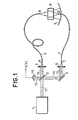
- the interferometer shown has in common with the conventional MICHELSON interferometer a source 1 of monochromatic radiation which emits a beam 11 in the direction of an optical divider 2 constituted for example by a plane semi-reflecting plate.
- the radiation 11 incident on the blade 2 splits into a first transmitted portion 12 and a second reflected portion 14.
- the transmitted portion 12 is focused by a lens 4 at the input A of a first optical waveguide 6 which re-emits this portion of radiation by its output B.
- the reflected portion 14 is returned by a mirror 3 to a lens which focuses the radiation 15 on the input C of a second optical waveguide 7.
- the end D of the waveguide 7 radiates a diverging beam which goes at the meeting of the divergent beam radiated by the end B of the waveguide 6. If it were a conventional MICHELSON interferometer, one could for example metallize the terminations B and D to return the two portions of radiation towards the plate 2 which ensures their superposition in a beam 13.
- the interference of the two radiation portions is detected by the photodetector 10 which delivers a signal S (t) representative of the movement of the interference fringes.
- the two measuring arms of the interferometer are then made up of one of elements 4, 6 and the other of elements 3, 5,7.
- the interferometer of FIG. 1 uses a photorefractive medium 8 and a concave spherical mirror 9 to reflect from B to A and from D to C the portions of radiation which have circulated in the two measuring arms.
- the concave spherical mirror 9 is arranged to receive through the medium 8 a spherical wave front coming from the end B so that this wave front is reflected under normal incidence and comes to focus on the end B.
- this reflective termination of the waveguide 6 would be conventional.
- the photorefractive medium 8 cooperates with the mirror 9 and the pumping radiation from the end B to return to the end D a radiation which has the conjugate phase of the radiation emitted by this end D and which converges there spontaneously.
- BSO bismuth-silicon oxide
- BGO bismuth-germanium oxide
- barium titanate B a T; 0 3 and potassium niobate KN b 0 3 it is possible to use the crystals of bismuth-silicon oxide (BSO), of bismuth-germanium oxide (BGO), but also barium titanate B a T; 0 3 and potassium niobate KN b 0 3 .
- a photorefractive medium is a photoexcitable medium in which incident photons create charge carriers which can diffuse within the material when the illumination comprises dark zones alternating with light zones.
- This medium is also electro-optical, which makes it possible to observe variations in the refractive index generated by the internal electric field which, itself, comes from the migration of the charge carriers.
- a photorefractive medium can be optically conditioned by interfering therewith a signal beam and a pumping beam. The network of fringes generates strata of different refracton index which, by diffracting the pumping beam, can generate a conjugated signal beam. This occurs in accordance with the technique of four-wave interferometry, when the pumping beam which has passed through the medium is returned to it by a mirror ensuring the reverse return.
- the radiation which emerges from the end B and which passes through the photorefractive medium 8 arrives with normal incidence on the reflecting surface of the mirror 9 which returns it towards the end B after passing through the medium 8.
- This radiation can be considered as the pumping beam of the photorefractive medium 8.
- the radiation coming from the end D of the waveguide 7 then constitutes a signal beam which interferes within the photorefractive medium 8 with the pumping beam.
- This interference spatially modulates the refractive properties of the photorefractive medium and there develops a system of strata of different refractive index which can be considered as a dynamic hologram of the structure of the radiation contained in the signal beam.
- the dynamic hologram diffracts towards the end D of the waveguide 7 a conjugate reconstruction of the radiation which emerges from this end.
- the conjugate reconstruction is the associated regressive electromagnetic wave having isomorphic wave fronts with change of sign of the phase shift, this one being evaluated taking as reference the phase reference of the pumping beam.
- the network of strata of the photorefractive medium 8 behaves like a reflecting mirror with respect to the end D of the second measuring arm of the interferometer.
- This reflecting function does not impose any particular condition on the signal beam, provided that the return of the pumping radiation by the mirror 9 retains the shape of the wave fronts.
- Source 1 is for example a helium-neon laser or a single-mode semiconductor laser. It is also possible to use a mode filter to eliminate parasitic oscillation modes and for this purpose the optical divider 2 can be effective when it is in the form of an integrated optical circuit with single-mode waveguides.
- phase shift ⁇ will also be produced between D and C during the reverse return along the second measuring arm.
- the reflective effect of the photorefractive medium results in the sending to the end D of a signal beam having the conjugate phase - ⁇ .
- the algebraic sum of the phase shifts caused by a reciprocal effect for a round trip of the radiation in the second arm of the interferometer does not cause a shift of fringes in steady state.
- the interferometer is insensitive to the reciprocal effect, whereas with a conventional mirror, a fringe offset proportional to 2 ⁇ ⁇ would have been obtained.
- the insensitivity to the reciprocal effect may be imperfect if the effect has varied between the outward journey and the return, which implies an extremely rapid variation in practice.
- the adaptive faculties of the photorefractive medium can cause a slow variation of reciprocal effect to be followed with agility by the dynamic hologram, while a more rapid variation introduces dragging thanks to which this type of variation is perceived by an offset of fringes.
- the phase difference produced between D and C is ⁇ . It has been assumed here that the non-reciprocal effect has the same amplitude in both directions, which is most often the case in practice.
- the photorefractive medium 8 generates the conjugate phase shift - ⁇ , we see that the round trip in the second measurement arm gave rise to a phase shift - 2 ⁇ which produces a displacement of fringes. If it had been a conventional mirror, the non-reciprocal effect would not have produced displacement of fringes.
- the interferometer of FIG. 1 is therefore entirely applicable to the measurement of the electric current via the FARADAY effect or to that of a gyration speed via the relativistic effect. In this type of application, it is necessary to wind an electrical conductor around at least one of the waveguides 6 and 7, or to wind at least one of these on a mandrel, as is done with ring interferometers.
- Figure 2 shows schematically the essential elements of Figure 1 with, in the first measuring arm, a fictitious source 100 which symbolizes the manifestation of a reciprocal effect by a phase shift ⁇ and that of a non-reciprocal effect by a phase shift AH.
- the arrows in solid lines represent the circulation of radiation with the phase shifts acquired due to a reciprocal effect.
- the dotted arrows give the same kind of information for a non-reciprocal effect.
- the pumping wave reaches the medium 8 with a phase shift ⁇ which is preserved until the effect reciprocal doubled it during the reverse return.
- the interaction within the photorefractive medium integrates a phase shift ⁇ , but during the generation of the conjugate signal radiation, the phase shift ⁇ of the pumping wave is added to the phase shift ⁇ of the index network represented in FIG. 2 by dotted strata. It follows that the radiated energy returned to the blade 2 by the two measuring arms has undergone the same phase shifts 2 ⁇ , so that no fringe shift is detected by the detector 10.
- phase shifts ⁇ and 2 ⁇ obey the same relationships at the location of the photorefractive medium 8 but, the radiation collected in return by the plate 2 coming from the first measuring arm does not show no more phase shift.
- the detector 10 therefore detects a fringe shift proportional to 2 ⁇ .
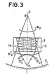
- FIG. 3 the behavior of the photorefractive medium has been detailed with the configuration adopted in FIG. 1.
- the wavefront pumping wave Ep centered on the end B of the first measurement arm, interferes with the wave wavefront signal ⁇ p from the end D of the second measurement arm.
- Strata of index 16 are thus created in the medium 8.
- the pumping wave reflected by the mirror 9 of center B has a wavefront Y r p which goes up along the axis X towards the end B ; this wave is diffracted by the strata 16 giving rise to a combined reconstruction of the signal wave.
- This reconstruction is characterized by the conjugate wave front ⁇ ⁇ o which converges towards the end D of the second measuring arm.
- polarization means can be inserted in one of the measurement arms, a quarter-wave plate being inserted between the photorefractive medium and the spherical mirror.
Landscapes
- Physics & Mathematics (AREA)
- Engineering & Computer Science (AREA)
- General Physics & Mathematics (AREA)
- Spectroscopy & Molecular Physics (AREA)
- Nonlinear Science (AREA)
- Optics & Photonics (AREA)
- Crystallography & Structural Chemistry (AREA)
- Ceramic Engineering (AREA)
- Chemical & Material Sciences (AREA)
- Electromagnetism (AREA)
- Power Engineering (AREA)
- Radar, Positioning & Navigation (AREA)
- Remote Sensing (AREA)
- Instruments For Measurement Of Length By Optical Means (AREA)
- Gyroscopes (AREA)
- Measuring Magnetic Variables (AREA)
Claims (8)
Strahlenbündelteilungsmittel (2), welches von der Strahlungsquelle ein Strahlenbündel empfängt und einen ersten Teil des genannten Strahlenbündels an einen ersten Messarm (6) sowie einen zweiten Teil des genannten Strahlenbündels an einen zweiten Messarm (7) sendet,
Strahlenbündelteilungsmittel (2) kombiniert worden sind.
Emissionsenden (B, D) der ersten und zweiten Lichtleitfasern gesendeten ersten und zweiten Strahlenbündelteile jeweils Kugelwellen sind.
Applications Claiming Priority (2)
| Application Number | Priority Date | Filing Date | Title |
|---|---|---|---|
| FR8120958A FR2516232B1 (fr) | 1981-11-09 | 1981-11-09 | Interferometre de type michelson a miroir photorefractif |
| FR8120958 | 1981-11-09 |
Publications (2)
| Publication Number | Publication Date |
|---|---|
| EP0079268A1 EP0079268A1 (de) | 1983-05-18 |
| EP0079268B1 true EP0079268B1 (de) | 1987-07-22 |
Family
ID=9263827
Family Applications (1)
| Application Number | Title | Priority Date | Filing Date |
|---|---|---|---|
| EP82401987A Expired EP0079268B1 (de) | 1981-11-09 | 1982-10-27 | Michelson-Typ Interferometer mit photorefraktivem Spiegel |
Country Status (5)
| Country | Link |
|---|---|
| US (1) | US4571080A (de) |
| EP (1) | EP0079268B1 (de) |
| JP (1) | JPS5892902A (de) |
| DE (1) | DE3276839D1 (de) |
| FR (1) | FR2516232B1 (de) |
Families Citing this family (21)
| Publication number | Priority date | Publication date | Assignee | Title |
|---|---|---|---|---|
| FR2541767B1 (fr) * | 1983-02-25 | 1986-11-21 | Thomson Csf | Hydrophone a fibre optique |
| FR2554596B1 (fr) * | 1983-11-04 | 1985-12-27 | Thomson Csf | Dispositif interferometrique de mesure d'une vitesse de rotation angulaire |
| US4803429A (en) * | 1986-09-15 | 1989-02-07 | California Institute Of Technology | Recovering polarization of light of arbitrary polarization propagating through distoring medium by phase conjugation reflection back through said medium |
| US4859844A (en) * | 1988-02-24 | 1989-08-22 | Hughes Aircraft Company | Comb filter pressure/temperature sensing system |
| US4921353A (en) * | 1988-07-05 | 1990-05-01 | Rockwell International Corporation | High speed photorefractive image comparator |
| US4938596A (en) * | 1989-01-05 | 1990-07-03 | The University Of Rochester | Phase conjugate, common path interferometer |
| GB9014989D0 (en) * | 1990-07-06 | 1990-08-29 | Nat Res Dev | Velocimeters |
| US5018852A (en) * | 1990-08-16 | 1991-05-28 | The United States Of America As Represented By The Administrator Of The National Aeronautics And Space Administration | Motion detection, novelty filtering, and target tracking using an interferometric technique with GaAs phase conjugate mirror |
| GB9104780D0 (en) * | 1991-03-07 | 1991-04-17 | Tatam Ralph P | Apparatus and methods for measuring magnetic fields and electric currents |
| EP0689067A3 (de) * | 1994-06-22 | 1997-04-09 | Fujitsu Ltd | Herstellungsverfahren für ein optisches Wellenleitersystem, optisches Bauelement und optischer Koppler mit dessen Verwendung, optisches Netzwerk und optische Leiterplatte |
| US5854868A (en) * | 1994-06-22 | 1998-12-29 | Fujitsu Limited | Optical device and light waveguide integrated circuit |
| DE19515365C2 (de) * | 1995-05-02 | 1997-11-20 | Deutsche Forsch Luft Raumfahrt | Faseroptische Lichtschranke |
| FR2754893B1 (fr) * | 1996-10-21 | 1999-01-08 | Sfim Ind | Gyroscope a fibre optique multimode |
| FR2755516B1 (fr) | 1996-11-05 | 1999-01-22 | Thomson Csf | Dispositif compact d'illumination |
| NL1009366C2 (nl) * | 1998-06-10 | 1999-12-13 | Stichting Tech Wetenschapp | Interferometer. |
| FR2784185B1 (fr) | 1998-10-06 | 2001-02-02 | Thomson Csf | Dispositif pour l'harmonisation entre une voie d'emission laser et une voie passive d'observation |
| FR2819061B1 (fr) * | 2000-12-28 | 2003-04-11 | Thomson Csf | Dispositif de controle de polarisation dans une liaison optique |
| CA2433797A1 (en) * | 2001-01-11 | 2002-07-18 | The Johns Hopkins University | Assessment of tooth structure using laser based ultrasonics |
| FR2860291B1 (fr) * | 2003-09-26 | 2005-11-18 | Thales Sa | Dispositif capteur de vitesse de rotation interferometrique a fibre optique |
| US8430059B2 (en) | 2008-06-11 | 2013-04-30 | Boston Scientific Scimed, Inc. | Precision pen height control for micro-scale direct writing technology |
| FR3049135B1 (fr) * | 2016-03-15 | 2020-02-14 | Cailabs | Dispositf de communications par fibre optique multimode avec composant de compensation de dispersion modale |
Family Cites Families (6)
| Publication number | Priority date | Publication date | Assignee | Title |
|---|---|---|---|---|
| FR2416452A2 (fr) * | 1977-03-23 | 1979-08-31 | Thomson Csf | Dispositif de visualisation, par interferometrie holographique, des deformations de structures deformables |
| FR2385079A1 (fr) * | 1977-03-23 | 1978-10-20 | Thomson Csf | Dispositif de visualisation, par interferometrie holographique, des deformations de structures deformables |
| US4198162A (en) * | 1978-05-23 | 1980-04-15 | Bell Telephone Laboratories, Incorporated | Tunable wide angular aperture filter by degenerate four-wave mixing |
| FR2449301A1 (fr) * | 1979-02-16 | 1980-09-12 | Thomson Csf | Dispositif optique de copie d'objets plans |
| FR2466042A1 (fr) * | 1979-09-21 | 1981-03-27 | Thomson Csf | Dispositif d'enregistrement holographique et systeme optique de traitement d'information comportant un tel dispositif |
| FR2482325A1 (fr) * | 1980-05-08 | 1981-11-13 | Thomson Csf | Systeme optique d'observation en temps reel a balayage |
-
1981
- 1981-11-09 FR FR8120958A patent/FR2516232B1/fr not_active Expired
-
1982
- 1982-09-28 US US06/425,698 patent/US4571080A/en not_active Expired - Lifetime
- 1982-10-27 EP EP82401987A patent/EP0079268B1/de not_active Expired
- 1982-10-27 DE DE8282401987T patent/DE3276839D1/de not_active Expired
- 1982-11-09 JP JP57196671A patent/JPS5892902A/ja active Granted
Also Published As
| Publication number | Publication date |
|---|---|
| EP0079268A1 (de) | 1983-05-18 |
| DE3276839D1 (en) | 1987-08-27 |
| US4571080A (en) | 1986-02-18 |
| JPH0236166B2 (de) | 1990-08-15 |
| JPS5892902A (ja) | 1983-06-02 |
| FR2516232B1 (fr) | 1986-02-21 |
| FR2516232A1 (fr) | 1983-05-13 |
Similar Documents
| Publication | Publication Date | Title |
|---|---|---|
| EP0079268B1 (de) | Michelson-Typ Interferometer mit photorefraktivem Spiegel | |
| Dakin et al. | Optical fiber sensors | |
| EP0120737B1 (de) | Faseroptischer Wasserschallempfänger | |
| EP0270429B1 (de) | Optisch integrierter Lesekopf zum Auslesen von auf einem magnetischen Träger aufgezeichneten Informationen | |
| US7557930B2 (en) | Bessel beam interferometer and measurement method | |
| EP0061360B1 (de) | Optische Vorrichtung zum Unterhalten eines in einem Monomode-Wellenleiter zirkulierenden Strahlungsenergieimpulses; Gyrometer und Hydrophon mit einer solchen Vorrichtung | |
| US5946429A (en) | Time-division multiplexing of polarization-insensitive fiber optic michelson interferometric sensor | |
| FR2738634A1 (fr) | Dispositif de mesure de dispersion de polarisation et procede de mesure correspondant | |
| EP0031274A1 (de) | Ring-interferometrische Vorrichtung und deren Verwendung zum Nachweisen nicht-gegenseitiger Effekte | |
| JPS6352033A (ja) | 光ファイバの時間的に分散される後方散乱量を光学的に測定する為の装置 | |
| EP0437404B1 (de) | Fühler zum Feststellen und Messen der Drehung der Polarisationsebene von Licht | |
| EP0266249A1 (de) | Dreiachsiges optisches Fiberringinterferometer | |
| EP0063977B1 (de) | Optische Interferometereinrichtung mit Phasenkonjugierungsspiegel, insbesondere für Laser-Gyrometer | |
| EP0141739B1 (de) | Interferometrische Anordnung zum Messen einer Winkeldrehgeschwindigkeit | |
| FR2547409A1 (fr) | Compensateur d'oscillations pour gyroscope a laser en anneau | |
| EP1664675B1 (de) | Faseroptische interferometrische messvorrichtung zur drehgeschwindigkeitsmessung | |
| FR2765964A1 (fr) | Dispositif optique de mesure de distance avec une grande precision | |
| EP0591912B1 (de) | Interferometer, bestehend aus einer integrierten Anordnung und einem Spiegel, die durch eine Messzone voneinander getrennt sind | |
| EP1119756B1 (de) | Erzeugung einer elektromagnetischen impulsfolge zum prüfen von glasfasern | |
| Jędrzejewska-Szczerska et al. | The optimal construction of fiber-optic Fabry-Perot interferometer | |
| FR2633713A1 (fr) | Procede et appareil a fibre optique, comprenant un coupleur directionnel, pour la detection d'un taux de rotation | |
| FR2696545A1 (fr) | Interféromètre comprenant un ensemble intégré et une unité réfléchissante séparés l'un de l'autre par une région de mesure. | |
| EP4630762A1 (de) | Vorrichtung zur messung einer physikalischen grösse unter verwendung des optischen vernier-effekts | |
| FR2463917A1 (fr) | Capteur optique | |
| FR2465202A1 (fr) | Interferometre en anneau |
Legal Events
| Date | Code | Title | Description |
|---|---|---|---|
| PUAI | Public reference made under article 153(3) epc to a published international application that has entered the european phase |
Free format text: ORIGINAL CODE: 0009012 |
|
| AK | Designated contracting states |
Designated state(s): DE GB NL SE |
|
| 17P | Request for examination filed |
Effective date: 19831010 |
|
| GRAA | (expected) grant |
Free format text: ORIGINAL CODE: 0009210 |
|
| AK | Designated contracting states |
Kind code of ref document: B1 Designated state(s): DE GB NL SE |
|
| REF | Corresponds to: |
Ref document number: 3276839 Country of ref document: DE Date of ref document: 19870827 |
|
| PLBE | No opposition filed within time limit |
Free format text: ORIGINAL CODE: 0009261 |
|
| STAA | Information on the status of an ep patent application or granted ep patent |
Free format text: STATUS: NO OPPOSITION FILED WITHIN TIME LIMIT |
|
| 26N | No opposition filed | ||
| EAL | Se: european patent in force in sweden |
Ref document number: 82401987.1 |
|
| PGFP | Annual fee paid to national office [announced via postgrant information from national office to epo] |
Ref country code: DE Payment date: 20010918 Year of fee payment: 20 |
|
| PGFP | Annual fee paid to national office [announced via postgrant information from national office to epo] |
Ref country code: GB Payment date: 20010919 Year of fee payment: 20 |
|
| PGFP | Annual fee paid to national office [announced via postgrant information from national office to epo] |
Ref country code: SE Payment date: 20010920 Year of fee payment: 20 |
|
| PGFP | Annual fee paid to national office [announced via postgrant information from national office to epo] |
Ref country code: NL Payment date: 20011009 Year of fee payment: 20 |
|
| REG | Reference to a national code |
Ref country code: GB Ref legal event code: IF02 |
|
| PG25 | Lapsed in a contracting state [announced via postgrant information from national office to epo] |
Ref country code: GB Free format text: LAPSE BECAUSE OF EXPIRATION OF PROTECTION Effective date: 20021026 |
|
| PG25 | Lapsed in a contracting state [announced via postgrant information from national office to epo] |
Ref country code: NL Free format text: LAPSE BECAUSE OF EXPIRATION OF PROTECTION Effective date: 20021027 |
|
| EUG | Se: european patent has lapsed |
Ref document number: 82401987.1 |
|
| REG | Reference to a national code |
Ref country code: GB Ref legal event code: PE20 Effective date: 20021026 |
|
| NLV7 | Nl: ceased due to reaching the maximum lifetime of a patent |
Effective date: 20021027 |