EP0079271A1 - Abzweigschalter mit Leistungskontrolle durch einen Steuermodul - Google Patents
Abzweigschalter mit Leistungskontrolle durch einen Steuermodul Download PDFInfo
- Publication number
- EP0079271A1 EP0079271A1 EP82401990A EP82401990A EP0079271A1 EP 0079271 A1 EP0079271 A1 EP 0079271A1 EP 82401990 A EP82401990 A EP 82401990A EP 82401990 A EP82401990 A EP 82401990A EP 0079271 A1 EP0079271 A1 EP 0079271A1
- Authority
- EP
- European Patent Office
- Prior art keywords
- circuit breaker
- circuit
- relay
- module
- trip
- Prior art date
- Legal status (The legal status is an assumption and is not a legal conclusion. Google has not performed a legal analysis and makes no representation as to the accuracy of the status listed.)
- Granted
Links
- 238000012544 monitoring process Methods 0.000 claims abstract description 17
- 230000005284 excitation Effects 0.000 claims abstract description 10
- 230000005291 magnetic effect Effects 0.000 claims abstract description 3
- 239000004020 conductor Substances 0.000 claims description 12
- 239000003990 capacitor Substances 0.000 claims description 11
- 238000004804 winding Methods 0.000 claims description 8
- 238000010616 electrical installation Methods 0.000 claims description 3
- 230000005540 biological transmission Effects 0.000 claims description 2
- 238000009434 installation Methods 0.000 abstract description 5
- 230000005405 multipole Effects 0.000 abstract 1
- 239000003795 chemical substances by application Substances 0.000 description 12
- 239000004429 Calibre Substances 0.000 description 9
- 230000003068 static effect Effects 0.000 description 7
- 238000010586 diagram Methods 0.000 description 4
- 239000000835 fiber Substances 0.000 description 4
- 230000007935 neutral effect Effects 0.000 description 4
- 230000011664 signaling Effects 0.000 description 4
- 238000009825 accumulation Methods 0.000 description 1
- 230000000881 depressing effect Effects 0.000 description 1
- 230000005294 ferromagnetic effect Effects 0.000 description 1
- 238000004519 manufacturing process Methods 0.000 description 1
- 238000005259 measurement Methods 0.000 description 1
- 238000012806 monitoring device Methods 0.000 description 1
Images


Classifications
-
- H—ELECTRICITY
- H01—ELECTRIC ELEMENTS
- H01H—ELECTRIC SWITCHES; RELAYS; SELECTORS; EMERGENCY PROTECTIVE DEVICES
- H01H71/00—Details of the protective switches or relays covered by groups H01H73/00 - H01H83/00
- H01H71/10—Operating or release mechanisms
- H01H71/12—Automatic release mechanisms with or without manual release
- H01H71/123—Automatic release mechanisms with or without manual release using a solid-state trip unit
-
- H—ELECTRICITY
- H01—ELECTRIC ELEMENTS
- H01H—ELECTRIC SWITCHES; RELAYS; SELECTORS; EMERGENCY PROTECTIVE DEVICES
- H01H83/00—Protective switches, e.g. circuit-breaking switches, or protective relays operated by abnormal electrical conditions otherwise than solely by excess current
- H01H83/20—Protective switches, e.g. circuit-breaking switches, or protective relays operated by abnormal electrical conditions otherwise than solely by excess current operated by excess current as well as by some other abnormal electrical condition
-
- H—ELECTRICITY
- H01—ELECTRIC ELEMENTS
- H01H—ELECTRIC SWITCHES; RELAYS; SELECTORS; EMERGENCY PROTECTIVE DEVICES
- H01H71/00—Details of the protective switches or relays covered by groups H01H73/00 - H01H83/00
- H01H71/10—Operating or release mechanisms
- H01H71/12—Automatic release mechanisms with or without manual release
- H01H71/123—Automatic release mechanisms with or without manual release using a solid-state trip unit
- H01H2071/124—Automatic release mechanisms with or without manual release using a solid-state trip unit with a hybrid structure, the solid state trip device being combined with a thermal or a electromagnetic trip
-
- H—ELECTRICITY
- H01—ELECTRIC ELEMENTS
- H01H—ELECTRIC SWITCHES; RELAYS; SELECTORS; EMERGENCY PROTECTIVE DEVICES
- H01H83/00—Protective switches, e.g. circuit-breaking switches, or protective relays operated by abnormal electrical conditions otherwise than solely by excess current
- H01H83/20—Protective switches, e.g. circuit-breaking switches, or protective relays operated by abnormal electrical conditions otherwise than solely by excess current operated by excess current as well as by some other abnormal electrical condition
- H01H2083/203—Protective switches, e.g. circuit-breaking switches, or protective relays operated by abnormal electrical conditions otherwise than solely by excess current operated by excess current as well as by some other abnormal electrical condition with shunt trip circuits, e.g. NC contact in an undervoltage coil circuit
-
- H—ELECTRICITY
- H01—ELECTRIC ELEMENTS
- H01H—ELECTRIC SWITCHES; RELAYS; SELECTORS; EMERGENCY PROTECTIVE DEVICES
- H01H71/00—Details of the protective switches or relays covered by groups H01H73/00 - H01H83/00
- H01H71/10—Operating or release mechanisms
- H01H71/12—Automatic release mechanisms with or without manual release
- H01H71/24—Electromagnetic mechanisms
- H01H71/28—Electromagnetic mechanisms with windings acting in conjunction
-
- H—ELECTRICITY
- H01—ELECTRIC ELEMENTS
- H01H—ELECTRIC SWITCHES; RELAYS; SELECTORS; EMERGENCY PROTECTIVE DEVICES
- H01H71/00—Details of the protective switches or relays covered by groups H01H73/00 - H01H83/00
- H01H71/10—Operating or release mechanisms
- H01H71/12—Automatic release mechanisms with or without manual release
- H01H71/24—Electromagnetic mechanisms
- H01H71/32—Electromagnetic mechanisms having permanently magnetised part
-
- H—ELECTRICITY
- H02—GENERATION; CONVERSION OR DISTRIBUTION OF ELECTRIC POWER
- H02H—EMERGENCY PROTECTIVE CIRCUIT ARRANGEMENTS
- H02H3/00—Emergency protective circuit arrangements for automatic disconnection directly responsive to an undesired change from normal electric working condition with or without subsequent reconnection ; integrated protection
- H02H3/02—Details
- H02H3/04—Details with warning or supervision in addition to disconnection, e.g. for indicating that protective apparatus has functioned
Definitions
- an auxiliary power supply supplies the pilot module by connection conductors, and the circuit breaker must be equipped with a special winding for receiving the remote opening order.
- the present invention aims to remedy the aforementioned drawbacks and to allow the production of an improved pilot module with own current adaptable to single-circuit or multi-gauge connection circuit breakers, with a thermothermal or static trip unit.
- the circuit breaker according to the invention is characterized in that the circuit breaker comprises a tripping control mechanism piloted by a common sensitive electromagnetic tripping relay, the excitation of which results either from the remote opening order emitted by the tripping device at emission of the pilot module, either of a signal command transmitted by the differential trip unit of the circuit breaker lor.s of the appearance of a residual differential fault current on the network.
- the same trigger relay is thus used for the differential trigger and the emission trigger, and this relay is advantageously of the polarized type comprising at least one control coil.
- the pilot module with own current comprises by phase a current sensor with toroid crossed by the phase conductor L serving as primary winding without any power connection, the output signal of the sensor being used after rectification to charge a capacitor constituting a reservoir of energy suitable for supplying the electronic monitoring circuit, and in the event that the subscribed power is exceeded on issuance of the remote opening order of the relay, and on actuation of the indicator.
- the indicator of the pilot module is formed either by an electromechanical relay of the polarized type with signaling light integral with the movable pallet, or by an electronic counter intended to count and record the number of exceedances of the subscribed power.
- the circuit breaker can be adjusted at the factory to a predetermined fixed rating, for example 60A or 90A in the bipolar version, and 30A or 60A in the four-pole version.
- the circuit breaker can also be of multiple ratings, for example between 15A and 90A, the rating change being effected by an adjustment circuit cooperating with the overload release of the circuit breaker. If the subscribed power is exceeded, said overload release causes the local circuit breaker to trip before the remote module sends the remote opening order to the relay.
- the invention is described below as being applied to a bipolar connection circuit breaker (phase and neutral) mounted in a single-phase network, but it is obvious that the various characteristics of the invention are also applicable to circuit breakers having a number of different poles, in particular four-pole (three phases more neutral) for a three-phase network.
- a more neutral bipolar or unipolar connection circuit breaker 10 is connected downstream of an energy meter 12 in a single-phase alternative distribution network for supplying the low-voltage electrical installation of a customer. having subscribed to a predetermined subscription with a distribution company.
- the counter 12 is generally housed in an external electrical box accessible to the distributor agent while the connection circuit breaker 10 is arranged in the subscriber's room separate from the counter box 12 by a distance d which varies according to the distance.
- the display and the control by the agent of the caliber corresponding to the pricing of the subscription subscribed by the subscriber operate via a pilot module 14 arranged in the box nearby or inside of counter 12.
- the pilot module 14 comprises a device 16 for selecting the rating, for example provided with a plurality of resistors R 11 , R 12 ' R 13 ... connected in voltage divider bridge with adjustment slider 15.
- the selection device 16 cooperates with an electronic monitoring circuit 20 capable of detecting exceedances of the subscribed power corresponding to a predetermined rating displayed on the device 16.
- the output of the monitoring circuit 20 is connected to an indicator device 22 with external indicator 24 signaling housed in the box.
- a link circuit 26 with pilot wires 28, 30 intended to send a remote opening order to a first coil B 1 for tripping the circuit breaker 10 if the subscribed power is exceeded.
- the single-phase connection circuit breaker 10 can be of fixed rating or multiple rating, and includes a mechanism of operation 32 of the contacts 34, 36 of the two poles associated with the phase L and neutral H conductors.
- the mechanism 32 of the circuit breaker 10 is actuated either manually by a trip button 38 and a reset button 40, or automatically by the intermediate a trip bar (not shown) piloted by a trip block 48 with electromagnetic trip relay 42.
- the latter of the polarized type comprises a movable pallet 44 cooperating with the trip bar, and a fixed ferromagnetic cylinder head 46 supporting a second tripping coil B 2 supplied by the trip unit 48 fitted with an overload trip device of the static type with long delay and short delay circuit or of the magnetothermal type, and of a differential trip device with predetermined trip threshold.
- the two tripping coils B 1 and B 2 are mounted on the yoke 46 of the control relay 42 which is thus common to the differential trigger of the block 48, and to the emission trigger of the pilot module 14 for remote opening.
- the same trip coil 8 2 is used to actuate the relay 42 for opening the contacts 34, 36 whatever the nature of the fault current detected by the block 48.
- the remote opening of the circuit breaker 10 by the action of the pilot module 14 is inhibited in the event of accidental or deliberate interruption of the connection circuit 26.
- the coil B 1 of the trip relay 42 is not energized and the overshoot of the subscribed power is then simply displayed by the indicator light 24 of the pilot unit 14 after possible recording in the indicating device 22.
- the trip unit 48 of the connection circuit breaker 10 with differential protection can either include a standard magnetothermal trip device, or an electronic trip device, and it is either single-caliber or multi-caliber.
- a standard magnetothermal trip device or an electronic trip device, and it is either single-caliber or multi-caliber.
- the appropriate setting of the overload release of the block 48 is likely in case of exceeding the subscribed power to locally cause the prior opening of the circuit breaker 10 by excitation of the second coil B 2 of the relay 42, before l 'transmission by the pilot module 14 of the trigger signal ' remotely to the first coil B 1 of the relay 42. In this case, the subscriber is warned of the overshoot before the intervention of the pilot module 14 and of the indicator light 24, who remains stationary in a rest position.
- the indicating device 22 When the laying of the link circuit 26 between the pilot module 14 and a multi-fiber circuit breaker 10 is impossible (in the case of existing installations), the indicating device 22 simply signals that the power has been exceeded.
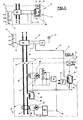
- FIG. 2 represents the simplified diagram of the electronic monitoring circuit 20 arranged in the pilot module 14.
- This circuit 20 comprises a current sensor 50, in particular a current transformer with toroid whose secondary winding provides a signal proportional to the current to monitor circulating in the primary winding formed by the phase conductor L.
- a diode bridge 52 rectifies the measurement signal from the sensor 50, and the output of the bridge 52 is connected to the voltage divider bridge with resistors R 11 , R 12 , R 13 ... forming the device for selecting the rating 16.
- the voltage taken from the cursor 18 of the selection device 16 is used to charge a capacitor C 11 which constitutes an energy reservoir used both for actuating the indicating device 22 and for exciting the tripping coil B 1 of the relay 42 and to the power supply of the amplifier (s) of circuit 20.
- a Zener diode 54 for protection shunts the capacitor C 11 and is connected in parallel to the terminals of a bias bias circuit 56 in series with a diode 58 connected to the negative input of an operational amplifier A0 1 .
- At the terminals of the accumulation capacitor C 11 is connected on the other hand a resistor time delay circuit 60 and series capacitor 62 whose intermediate point is connected to the positive input of the operational amplifier A0 1 .
- the output voltage of amplifier A0 1 drives a thyristor 64 inserted in series in the discharge circuit of capacitor C 11 .
- the voltage across the terminals of the capacitor 62 is insufficient to unblock the operational amplifier AO 1 .
- the voltage of the capacitor 62 unblocks the amplifier A0 1 which excites the trigger of the thyristor 64.
- the conduction of the latter causes the discharge of the capacitor C 11 in the indicating device 22 and in the connection circuit 26 for excitation of the coil B 2 for remote triggering of the relay 42.
- the coil B 2 can be connected in series or in parallel with the indicating device 22.
- the pilot module 14 is at its own current and does not require no connection for an auxiliary power supply.
- FIG. 3 shows an embodiment of the indicating device 22 with signaling light 24.
- the assembly consists of an electromagnetic relay 68 polarized of the same type as that of the relay 42 for triggering the mechanism 32 of the circuit breaker 10.
- a control winding 66 mounted on the yoke of the relay 68 is supplied by the monitoring device 20 with its own current during the conduction of the thyristor 64, and causes the movable paddle 70 to detach to a separated position.
- the mechanical indicator 24 secured to the pallet 70 is projecting to indicate that the power subscribed to the agent has been exceeded. The latter operates the reset of the signaling relay 68 by depressing a push button 72 urging the pallet 70 in the position of attraction against the cylinder head.
- the indicating device 22 could be produced by an electronic counter intended to count the number of exceedances of the subscribed power.
- a recorder associated with the meter would indicate the exact date of these exceedances to the controller.
- FIG. 4 illustrates the application of a pilot module 14 according to the invention to a connection circuit breaker 10 with a trip unit 48 static.
- the same references will be used subsequently to designate identical or similar parts or components.
- the trip unit 48 of the circuit breaker 10 is for example of the type described in French patent application 81 05153 of March 10, 1981, filed by the applicant.
- This block 48 includes a static overload trip device with electronic processing circuit 76 having a first long delay circuit and a second short delay circuit controlled by a current sensor 78 similar to that of the pilot module 14.
- the sensor 78 provides a proportional signal to the current flowing through the conductor L of the circuit breaker 10, and a rectifier bridge 80 rectifies this signal applied to an adjustment circuit 82 of the rating of the circuit breaker by the subscriber.
- This adjusting circuit 82 is similar to that of the selection device 16 of driver module 14, and includes re s i n sta these R 21, R 22 'R 23 ... arranged in the divider bridge voltage slider .
- a capacitor C21 energy accumulator is inserted between the resistance bridge and the electronic circuit 76, the output of which controls a switching circuit 84 connected to the second coil 8 2 for triggering the relay 42.
- the block 48 further comprises a standard trigger electromagnetic 86 instantaneous with fixed trip threshold, sensitive to high short-circuit currents.
- This trigger 86 is provided with a yoke 88 surrounded by one or more turns of the conductor L, and a pivoting pallet 90 mechanically cooperating with the trigger bar of the mechanism 32.
- a differential fault is detected in the block 48 by a trigger differential 92 with toroid 94 surrounding conductors L and N.
- the secondary winding 96 of torus 94 is connected to a rectifier bridge 98 connected to an electronic control circuit 100 fixing the differential tripping threshold.
- This circuit 100 cooperates with the switching circuit 84 to energize the coil 82 of the relay 42 after exceeding the threshold.
- the electronic circuits 76 and 100 are clean current and do not require any auxiliary power source.
- connection circuit between the pilot module 14 and the circuit breaker 10 comprises a single pilot wire 30, the other 28 pilot wire for connection of the first trigger coil B 1 being connected to the conductor L of the network playing the role of return conductor.
- the remote control of the circuit breaker 10 from the pilot module 14 is impossible, and the excess power is simply displayed on the indicator 22 of the pilot module 14.
- the opening of the circuit breaker 10 on fault can nevertheless intervene by the action of the differential trip unit 92 or the instantaneous electromagnetic trip unit 86 when a differential fault or short-circuit current occurs.
- the long delay tripping circuit associated with the sensor 78 also causes the circuit breaker 10 to open by exciting the tripping coil B 2 of the relay 42 when the current flowing through the circuit breaker 10 exceeds 90 amperes.
- the rating displayed on the adjustment circuit 82 of the static overload release of circuit breaker 10 corresponds to that of the selection device 16 of the pilot module 14, for example 30 amperes for a subscribed power of 6 kW.
- the time constant of the delay circuit with resistance 60 and capacitance 62 associated with the operational amplifier AO 1 of the pilot module 14 is greater than the time constant of the delay circuit of the trip circuit lonq delay of the block 49 of the circuit breaker 10, so as to ensure, when the subscribed power is exceeded, the opening of the circuit breaker 10 due to the excitation of the coil B 2 by the block 45, before the emission by the pilot module 14 of the remote trip signal at coil B 1 of relay 42.
- the subscriber is thus warned of the overshoot before the intervention of the pilot module 14.
- the subscriber For frequent overshoots, the subscriber must request an increase in the subscribed power, for example 9 kW adjusted by the agent on the caliber 45A of the selection circuit 16 of the pilot module 14.
- the subscriber can then display the caliber 45A on the adjustment circuit 82 of the circuit breaker 10.
- FIG. 5 represents the application of a pilot module 14 according to the invention to a single-phase connection circuit breaker 10 with magneto-thermal and differential trip unit.
- the secondary winding 96 of the differential trip device 92 with toroid 94 is connected directly and via an amplifier (in dotted lines) to the coil B 2 of the relay 42 for tripping the circuit breaker 10.
- the magnetic circuit 46 of the relay 42 carries the coil B 1 controlled by the pilot module 14.
- the overload trigger is formed by a bimetal strip 102 inserted in the conductor L, and cooperating directly with the trigger bar of the mechanism 32 during maximum deflection occurring after exceeding the displayed rating on the circuit breaker. The subscriber can adjust this rating by means of shunt resistors 104 for the bimetal strip 102.
- circuit breaker can be single-caliber or multi-fiber.
- the bimetal strip 102 will be adjusted to cause tripping when the subscribed power is exceeded of the circuit breaker 10 by unlocking the mechanism 32, before the intervention of the module 14.
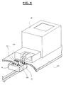
- FIG. 6 illustrates the arrangement of the pilot module 14 mounted tamper-proof in the table 108 of the counter 12.
- the leads L and N of the outlet of the counter 12 pass through an opening 110 formed in the front face of the table 108, and the pilot module 14 with own current is placed under the front face of the table.
- the toroid of the current sensor 50 is disposed opposite the opening 110 and surrounds the phase conductor L.
- the installation of the pilot module 14 does not require any power connection.
- the front face is provided with a porthole or with a transparent part for viewing the indicator light 24.
Landscapes
- Emergency Protection Circuit Devices (AREA)
- Remote Monitoring And Control Of Power-Distribution Networks (AREA)
Applications Claiming Priority (2)
| Application Number | Priority Date | Filing Date | Title |
|---|---|---|---|
| FR8120991 | 1981-11-06 | ||
| FR8120991A FR2516305A1 (fr) | 1981-11-06 | 1981-11-06 | Disjoncteur de branchement a controle de la puissance souscrite par un module pilote |
Publications (2)
| Publication Number | Publication Date |
|---|---|
| EP0079271A1 true EP0079271A1 (de) | 1983-05-18 |
| EP0079271B1 EP0079271B1 (de) | 1986-01-29 |
Family
ID=9263846
Family Applications (1)
| Application Number | Title | Priority Date | Filing Date |
|---|---|---|---|
| EP19820401990 Expired EP0079271B1 (de) | 1981-11-06 | 1982-10-27 | Abzweigschalter mit Leistungskontrolle durch einen Steuermodul |
Country Status (5)
| Country | Link |
|---|---|
| EP (1) | EP0079271B1 (de) |
| DE (1) | DE3268879D1 (de) |
| ES (1) | ES8308150A1 (de) |
| FR (1) | FR2516305A1 (de) |
| PT (1) | PT75713B (de) |
Cited By (8)
| Publication number | Priority date | Publication date | Assignee | Title |
|---|---|---|---|---|
| EP0105786A1 (de) * | 1982-09-30 | 1984-04-18 | Merlin Gerin | Abzweigschalter mit einem elektronischen Auslöser und einer ferngesteuerten Einstellung |
| FR2629261A1 (fr) * | 1987-12-16 | 1989-09-29 | Gen Electric | Disjoncteur en boitier moule et ensemble de declenchement en derivation |
| EP1059654A3 (de) * | 1999-06-08 | 2002-01-23 | Sorenson, Richard W., c/o Carlingswitch, Inc. | Thermischer Lastschalter |
| EP1059653A3 (de) * | 1999-06-08 | 2002-01-23 | Sorenson, Richard W., c/o Carlingswitch, Inc. | Thermischer Lastschalter |
| EP1079408A3 (de) * | 1999-08-27 | 2003-03-26 | General Electric Company | Zusätzliche Auslöseeinheit für drehbare Schutzschalter |
| CN108987203A (zh) * | 2018-09-21 | 2018-12-11 | 国网福建省电力有限公司 | 一种具有自动分合能力的智能空开装置 |
| WO2021214235A1 (fr) * | 2020-04-24 | 2021-10-28 | Hager-Electro Sas | Disjoncteur a commande de declenchement electronique |
| CN116110753A (zh) * | 2023-04-11 | 2023-05-12 | 宁波天安智能电网科技股份有限公司 | 一种可调式的断路器安全回路系统 |
Families Citing this family (2)
| Publication number | Priority date | Publication date | Assignee | Title |
|---|---|---|---|---|
| DE102008052949B4 (de) * | 2008-10-23 | 2010-10-21 | Siemens Aktiengesellschaft | Verfahren zum Schutz vor Überspannung in einem an ein Stromversorgungsnetz angeschlossenen System, Überspannungsschutzgerät und Anordnung mit einem solchen |
| FR2997573B1 (fr) | 2012-10-26 | 2015-01-02 | Hager Electro Sas | Communication sans cablage dedie a partir d'un circuit surveille pour l'action sur un sectionneur amont |
Citations (4)
| Publication number | Priority date | Publication date | Assignee | Title |
|---|---|---|---|---|
| FR2283542A1 (fr) * | 1974-08-28 | 1976-03-26 | Merlin Gerin | Disjoncteur differentiel a haut pouvoir de coupure |
| US4068283A (en) * | 1976-10-01 | 1978-01-10 | General Electric Company | Circuit breaker solid state trip unit incorporating trip indicating circuit |
| FR2440609A1 (fr) * | 1978-11-06 | 1980-05-30 | Merlin Gerin | Bloc auxiliaire de commande d'ouverture d'un disjoncteur de protection differentielle |
| US4213165A (en) * | 1978-03-16 | 1980-07-15 | Square D Company | Circuit breaker having an electronic fault sensing and trip initiating unit |
-
1981
- 1981-11-06 FR FR8120991A patent/FR2516305A1/fr active Granted
-
1982
- 1982-10-21 PT PT7571382A patent/PT75713B/pt unknown
- 1982-10-27 EP EP19820401990 patent/EP0079271B1/de not_active Expired
- 1982-10-27 DE DE8282401990T patent/DE3268879D1/de not_active Expired
- 1982-11-04 ES ES517099A patent/ES8308150A1/es not_active Expired
Patent Citations (4)
| Publication number | Priority date | Publication date | Assignee | Title |
|---|---|---|---|---|
| FR2283542A1 (fr) * | 1974-08-28 | 1976-03-26 | Merlin Gerin | Disjoncteur differentiel a haut pouvoir de coupure |
| US4068283A (en) * | 1976-10-01 | 1978-01-10 | General Electric Company | Circuit breaker solid state trip unit incorporating trip indicating circuit |
| US4213165A (en) * | 1978-03-16 | 1980-07-15 | Square D Company | Circuit breaker having an electronic fault sensing and trip initiating unit |
| FR2440609A1 (fr) * | 1978-11-06 | 1980-05-30 | Merlin Gerin | Bloc auxiliaire de commande d'ouverture d'un disjoncteur de protection differentielle |
Cited By (12)
| Publication number | Priority date | Publication date | Assignee | Title |
|---|---|---|---|---|
| EP0105786A1 (de) * | 1982-09-30 | 1984-04-18 | Merlin Gerin | Abzweigschalter mit einem elektronischen Auslöser und einer ferngesteuerten Einstellung |
| FR2629261A1 (fr) * | 1987-12-16 | 1989-09-29 | Gen Electric | Disjoncteur en boitier moule et ensemble de declenchement en derivation |
| EP1059654A3 (de) * | 1999-06-08 | 2002-01-23 | Sorenson, Richard W., c/o Carlingswitch, Inc. | Thermischer Lastschalter |
| EP1059653A3 (de) * | 1999-06-08 | 2002-01-23 | Sorenson, Richard W., c/o Carlingswitch, Inc. | Thermischer Lastschalter |
| EP1079408A3 (de) * | 1999-08-27 | 2003-03-26 | General Electric Company | Zusätzliche Auslöseeinheit für drehbare Schutzschalter |
| CN108987203A (zh) * | 2018-09-21 | 2018-12-11 | 国网福建省电力有限公司 | 一种具有自动分合能力的智能空开装置 |
| CN108987203B (zh) * | 2018-09-21 | 2020-01-31 | 国网福建省电力有限公司 | 一种具有自动分合能力的智能空开装置 |
| WO2021214235A1 (fr) * | 2020-04-24 | 2021-10-28 | Hager-Electro Sas | Disjoncteur a commande de declenchement electronique |
| FR3109665A1 (fr) * | 2020-04-24 | 2021-10-29 | Hager-Electro Sas | Disjoncteur à commande de déclenchement électronique |
| CN115699239A (zh) * | 2020-04-24 | 2023-02-03 | 黑格尔电镀物品股份公司 | 具有电子跳闸控制的断路器 |
| CN115699239B (zh) * | 2020-04-24 | 2026-05-12 | 黑格尔电镀物品股份公司 | 具有电子跳闸控制的断路器 |
| CN116110753A (zh) * | 2023-04-11 | 2023-05-12 | 宁波天安智能电网科技股份有限公司 | 一种可调式的断路器安全回路系统 |
Also Published As
| Publication number | Publication date |
|---|---|
| PT75713A (fr) | 1982-11-01 |
| ES517099A0 (es) | 1983-08-01 |
| DE3268879D1 (en) | 1986-03-13 |
| EP0079271B1 (de) | 1986-01-29 |
| ES8308150A1 (es) | 1983-08-01 |
| PT75713B (fr) | 1985-01-02 |
| FR2516305B1 (de) | 1983-12-23 |
| FR2516305A1 (fr) | 1983-05-13 |
Similar Documents
| Publication | Publication Date | Title |
|---|---|---|
| EP1329733B1 (de) | Integriertes Schutzsystem mit Lichtbogenfehlererfassung | |
| US5847913A (en) | Trip indicators for circuit protection devices | |
| JPH0334038Y2 (de) | ||
| US6477022B1 (en) | Ground fault of arc fault circuit breaker employing first and second separable contacts and plural actuating mechanisms | |
| FR2638909A1 (fr) | Declencheur differentiel a circuit test et a telecommande d'ouverture autoprotegee | |
| FR2547122A1 (fr) | Declencheur electronique selectif associe a un disjoncteur limiteur | |
| FR2832559A1 (fr) | Module de commande et de protection d'un appareil interrupteur | |
| AU2002301798B2 (en) | Circuit breaker for detecting an excessive voltage and tripping responsive thereto | |
| EP0079271B1 (de) | Abzweigschalter mit Leistungskontrolle durch einen Steuermodul | |
| US4308511A (en) | Load management circuit breaker | |
| CA1148590A (en) | Manually operable and shunt controllable circuit breaker | |
| EP2181457B1 (de) | Elektrische schaltvorrichtung, unterbrecherschalter und verfahren zum unterbrechen von überströmen einer leistungsschaltung | |
| EP0096601A1 (de) | Funktioneller Niederspannungs-Energieverteilungsblock | |
| US5095398A (en) | Electrical circuit breaker protection device | |
| EP0665623B1 (de) | Prüfeinrichtung für Differentialschutzschalter und diese Vorrichtung enthaltende Differentialschutzschalter | |
| FR2497013A1 (fr) | Dispositif de delestage d'une installation electrique basse tension | |
| EP0079270B1 (de) | Niederspannungsabzweigschalter mit einem ferngesteuerten Einstellschalter | |
| FR2752479A1 (fr) | Disjoncteur differentiel electronique | |
| FR3102293A1 (fr) | Appareil de protection d’une installation électrique en courant alternatif | |
| CA2572209A1 (en) | Two pole circuit interrupter employing a single arc fault or ground fault trip circuit | |
| WO2004049535A1 (de) | Schutzschalter | |
| EP0105786B1 (de) | Abzweigschalter mit einem elektronischen Auslöser und einer ferngesteuerten Einstellung | |
| CA2296983C (en) | Ground fault circuit breaker | |
| EP4016777B1 (de) | Stromschutzgerät einer elektrischen anlage mit wechselstrom | |
| EP3511970B1 (de) | Elektrischer schalter mit einem detektor welcher informationen über die auslösung des schalters in einen bus einspeist |
Legal Events
| Date | Code | Title | Description |
|---|---|---|---|
| PUAI | Public reference made under article 153(3) epc to a published international application that has entered the european phase |
Free format text: ORIGINAL CODE: 0009012 |
|
| AK | Designated contracting states |
Designated state(s): BE CH DE GB IT LI NL SE |
|
| 17P | Request for examination filed |
Effective date: 19830929 |
|
| ITF | It: translation for a ep patent filed | ||
| GRAA | (expected) grant |
Free format text: ORIGINAL CODE: 0009210 |
|
| AK | Designated contracting states |
Designated state(s): BE CH DE GB IT LI NL SE |
|
| REF | Corresponds to: |
Ref document number: 3268879 Country of ref document: DE Date of ref document: 19860313 |
|
| PLBE | No opposition filed within time limit |
Free format text: ORIGINAL CODE: 0009261 |
|
| STAA | Information on the status of an ep patent application or granted ep patent |
Free format text: STATUS: NO OPPOSITION FILED WITHIN TIME LIMIT |
|
| 26N | No opposition filed | ||
| PGFP | Annual fee paid to national office [announced via postgrant information from national office to epo] |
Ref country code: SE Payment date: 19910927 Year of fee payment: 10 |
|
| PGFP | Annual fee paid to national office [announced via postgrant information from national office to epo] |
Ref country code: CH Payment date: 19911025 Year of fee payment: 10 |
|
| ITTA | It: last paid annual fee | ||
| PGFP | Annual fee paid to national office [announced via postgrant information from national office to epo] |
Ref country code: NL Payment date: 19911031 Year of fee payment: 10 |
|
| PG25 | Lapsed in a contracting state [announced via postgrant information from national office to epo] |
Ref country code: SE Effective date: 19921028 |
|
| PG25 | Lapsed in a contracting state [announced via postgrant information from national office to epo] |
Ref country code: LI Effective date: 19921031 Ref country code: CH Effective date: 19921031 |
|
| PG25 | Lapsed in a contracting state [announced via postgrant information from national office to epo] |
Ref country code: NL Effective date: 19930501 |
|
| NLV4 | Nl: lapsed or anulled due to non-payment of the annual fee | ||
| REG | Reference to a national code |
Ref country code: CH Ref legal event code: PL |
|
| EUG | Se: european patent has lapsed |
Ref document number: 82401990.5 Effective date: 19930510 |
|
| PGFP | Annual fee paid to national office [announced via postgrant information from national office to epo] |
Ref country code: GB Payment date: 19961018 Year of fee payment: 15 |
|
| PGFP | Annual fee paid to national office [announced via postgrant information from national office to epo] |
Ref country code: BE Payment date: 19961212 Year of fee payment: 15 |
|
| PGFP | Annual fee paid to national office [announced via postgrant information from national office to epo] |
Ref country code: DE Payment date: 19971013 Year of fee payment: 16 |
|
| PG25 | Lapsed in a contracting state [announced via postgrant information from national office to epo] |
Ref country code: GB Free format text: LAPSE BECAUSE OF NON-PAYMENT OF DUE FEES Effective date: 19971027 |
|
| PG25 | Lapsed in a contracting state [announced via postgrant information from national office to epo] |
Ref country code: BE Free format text: LAPSE BECAUSE OF NON-PAYMENT OF DUE FEES Effective date: 19971031 |
|
| BERE | Be: lapsed |
Owner name: MERLIN GERIN Effective date: 19971031 |
|
| GBPC | Gb: european patent ceased through non-payment of renewal fee |
Effective date: 19971027 |
|
| PG25 | Lapsed in a contracting state [announced via postgrant information from national office to epo] |
Ref country code: DE Free format text: LAPSE BECAUSE OF NON-PAYMENT OF DUE FEES Effective date: 19990803 |