EP0079314A1 - Verbindungsvorrichtung für netzförmige Raumstrukturen und solche Vorrichtungen verwendende netzförmige Strukturen - Google Patents
Verbindungsvorrichtung für netzförmige Raumstrukturen und solche Vorrichtungen verwendende netzförmige Strukturen Download PDFInfo
- Publication number
- EP0079314A1 EP0079314A1 EP82830258A EP82830258A EP0079314A1 EP 0079314 A1 EP0079314 A1 EP 0079314A1 EP 82830258 A EP82830258 A EP 82830258A EP 82830258 A EP82830258 A EP 82830258A EP 0079314 A1 EP0079314 A1 EP 0079314A1
- Authority
- EP
- European Patent Office
- Prior art keywords
- reticular
- nodal
- reticular spatial
- structures
- fact
- Prior art date
- Legal status (The legal status is an assumption and is not a legal conclusion. Google has not performed a legal analysis and makes no representation as to the accuracy of the status listed.)
- Withdrawn
Links
Images


Classifications
-
- E—FIXED CONSTRUCTIONS
- E04—BUILDING
- E04B—GENERAL BUILDING CONSTRUCTIONS; WALLS, e.g. PARTITIONS; ROOFS; FLOORS; CEILINGS; INSULATION OR OTHER PROTECTION OF BUILDINGS
- E04B1/00—Constructions in general; Structures which are not restricted either to walls, e.g. partitions, or floors or ceilings or roofs
- E04B1/18—Structures comprising elongated load-supporting parts, e.g. columns, girders, skeletons
- E04B1/19—Three-dimensional [3D] framework structures
-
- E—FIXED CONSTRUCTIONS
- E04—BUILDING
- E04B—GENERAL BUILDING CONSTRUCTIONS; WALLS, e.g. PARTITIONS; ROOFS; FLOORS; CEILINGS; INSULATION OR OTHER PROTECTION OF BUILDINGS
- E04B1/00—Constructions in general; Structures which are not restricted either to walls, e.g. partitions, or floors or ceilings or roofs
- E04B1/18—Structures comprising elongated load-supporting parts, e.g. columns, girders, skeletons
- E04B1/19—Three-dimensional [3D] framework structures
- E04B1/1903—Connecting nodes specially adapted therefor
- E04B1/1912—Connecting nodes specially adapted therefor with central cubical connecting element
-
- E—FIXED CONSTRUCTIONS
- E04—BUILDING
- E04B—GENERAL BUILDING CONSTRUCTIONS; WALLS, e.g. PARTITIONS; ROOFS; FLOORS; CEILINGS; INSULATION OR OTHER PROTECTION OF BUILDINGS
- E04B1/00—Constructions in general; Structures which are not restricted either to walls, e.g. partitions, or floors or ceilings or roofs
- E04B1/18—Structures comprising elongated load-supporting parts, e.g. columns, girders, skeletons
- E04B1/19—Three-dimensional [3D] framework structures
- E04B1/1903—Connecting nodes specially adapted therefor
- E04B1/1912—Connecting nodes specially adapted therefor with central cubical connecting element
- E04B2001/1915—Connecting nodes specially adapted therefor with central cubical connecting element with strut engaging means at the edges of the cube
-
- E—FIXED CONSTRUCTIONS
- E04—BUILDING
- E04B—GENERAL BUILDING CONSTRUCTIONS; WALLS, e.g. PARTITIONS; ROOFS; FLOORS; CEILINGS; INSULATION OR OTHER PROTECTION OF BUILDINGS
- E04B1/00—Constructions in general; Structures which are not restricted either to walls, e.g. partitions, or floors or ceilings or roofs
- E04B1/18—Structures comprising elongated load-supporting parts, e.g. columns, girders, skeletons
- E04B1/19—Three-dimensional [3D] framework structures
- E04B1/1903—Connecting nodes specially adapted therefor
- E04B2001/1918—Connecting nodes specially adapted therefor with connecting nodes having flat radial connecting surfaces
-
- E—FIXED CONSTRUCTIONS
- E04—BUILDING
- E04B—GENERAL BUILDING CONSTRUCTIONS; WALLS, e.g. PARTITIONS; ROOFS; FLOORS; CEILINGS; INSULATION OR OTHER PROTECTION OF BUILDINGS
- E04B1/00—Constructions in general; Structures which are not restricted either to walls, e.g. partitions, or floors or ceilings or roofs
- E04B1/18—Structures comprising elongated load-supporting parts, e.g. columns, girders, skeletons
- E04B1/19—Three-dimensional [3D] framework structures
- E04B2001/1924—Struts specially adapted therefor
- E04B2001/1927—Struts specially adapted therefor of essentially circular cross section
- E04B2001/193—Struts specially adapted therefor of essentially circular cross section with flattened connecting parts, e.g. ends
-
- E—FIXED CONSTRUCTIONS
- E04—BUILDING
- E04B—GENERAL BUILDING CONSTRUCTIONS; WALLS, e.g. PARTITIONS; ROOFS; FLOORS; CEILINGS; INSULATION OR OTHER PROTECTION OF BUILDINGS
- E04B1/00—Constructions in general; Structures which are not restricted either to walls, e.g. partitions, or floors or ceilings or roofs
- E04B1/18—Structures comprising elongated load-supporting parts, e.g. columns, girders, skeletons
- E04B1/19—Three-dimensional [3D] framework structures
- E04B2001/1924—Struts specially adapted therefor
- E04B2001/1936—Winged profiles, e.g. with a L-, T-, U- or X-shaped cross section
-
- E—FIXED CONSTRUCTIONS
- E04—BUILDING
- E04B—GENERAL BUILDING CONSTRUCTIONS; WALLS, e.g. PARTITIONS; ROOFS; FLOORS; CEILINGS; INSULATION OR OTHER PROTECTION OF BUILDINGS
- E04B1/00—Constructions in general; Structures which are not restricted either to walls, e.g. partitions, or floors or ceilings or roofs
- E04B1/18—Structures comprising elongated load-supporting parts, e.g. columns, girders, skeletons
- E04B1/19—Three-dimensional [3D] framework structures
- E04B2001/1957—Details of connections between nodes and struts
- E04B2001/1963—Screw connections with axis at an angle, e.g. perpendicular, to the main axis of the strut
-
- E—FIXED CONSTRUCTIONS
- E04—BUILDING
- E04B—GENERAL BUILDING CONSTRUCTIONS; WALLS, e.g. PARTITIONS; ROOFS; FLOORS; CEILINGS; INSULATION OR OTHER PROTECTION OF BUILDINGS
- E04B1/00—Constructions in general; Structures which are not restricted either to walls, e.g. partitions, or floors or ceilings or roofs
- E04B1/18—Structures comprising elongated load-supporting parts, e.g. columns, girders, skeletons
- E04B1/19—Three-dimensional [3D] framework structures
- E04B2001/1981—Three-dimensional [3D] framework structures characterised by the grid type of the outer planes of the framework
- E04B2001/1984—Three-dimensional [3D] framework structures characterised by the grid type of the outer planes of the framework rectangular, e.g. square, grid
Definitions
- This invention concerns a connecting device for reticular spatial structures and also concerns structures set up with said device.
- this invention concerns a device able to form nodal junctions for connecting the rods in reticular spatial structures, which we shall also call grills or lattices hereinafter.
- the invention also concerns grills of which the nodal junctions are obtained by fitting together the devices of the invention.
- Spatial latticework and structures with a cubic mesh have a very great field of employment.
- a few examples thereof are flat roofing, or roofs of several pitches or in steps or of a pseudocupola type, etc. having small, medium and big.spans for cantilever roofs, parking lots, sheds, service stations, motels, workshops, churches, swimming pools, gymnasia, bowls courts, bowling alleys, tennis courts, buildings for restaurants, shops, supermarkets, areas for shows, exhibitions and markets, cinemas, concert halls, conference halls, auditoria, grandstands, cycle tracks, sports stadia, aircraft hangers, shelters for playgrounds and pedestrian islands, open sheds for agriculture and livestock husbandry, large greenhouses, beams for big spans, large-scale antennas and towers, bridges and marine platforms, bearing structures for private and public buildings, bearing structures for skyscrapers, underwater structures, structures above ground to enclose dwelling spaces, macrostructures of plants for alternative sources of energy, radar and telescope equipment, latticework for tanks, equipment
- cubic latticework finds an immediate application as a basic framework for structures resistant to earthquakes.
- the reticular constructional systrms at present on the market are relatively not very competitive with other building systems because either they (Mero type) have too high production costs owing to the extreme sophistication of processing and need skilled labour, or they (Unistrut type) are not very versatile as regards the use of types of grills or sections (only two-directional grills and U-shaped sections), or else they (Triodetic type) require special techniques and equipment for assembling the elements on the building site (pneumatic hammer for joining the ends of the rods to the nodal junction).
- the modular nature of the system should ensure excellent integration of the building components and also permit standardisation of computation of the structure, which, to be a cubic mesh, should comply with the laws and standards acquired to calculate its stresses without any need of a computer.
- Standardisation of the lattice should also represent an improvement in the "response" of the structure to seismic stresses.
- the device of the invention offers the following advantages in comparison to the prior art:-
- the spatial aggregations which can be made by using the device of the invention are almost unending: cubic lattices, latticework in layers, flat grills with a triangular and quadrangular module, corrugated grills, grills with several pitches and any slope, beams, latticework towers,cantilever structures, etc.
- cubic lattice finds an immediate application as a basic framework for structures to resist earthquakes.
- the device of the invention has a substantially quadrangular shape with a substantially square middle area and with four other perimetric areas sloped at 45° to the plane of the middle area, said perimetric areas comprising holes for assembly by means of nuts and bolts or possibly rivets.
- the nodal junction is formed with six devices of the invention fitted together, which connect a maximum of twelve rods and provide spatial grills.
- the nodal junction thus formed enables grills to be made with small, medium and large thicknesses for small, medium and large spans respectively.
- the device of the invention When the device of the invention is butt-welded to any rolled or drawn section the axis of which is perpendicular to the middle area of the device itself, it gives rise to a lattice formed in three orthogonal directions, which is cubic if all the rods employed are of the same size.
- the nodal junctions will have a prismatic shape with square bases if four of the devices are rectangular and two are square, or will have a parellelepipedal shape if the six devices fitted together to form the nodal junction are all rectangular and pairs of them are the same as each other.
- the rods which can be used in conjunction with the device of the invention and with the nodal junctions formed with said device consist normally of a rolled or drawn rod having an opened or closed section and comprising blade-wise ends belonging to the same plane as that on which the axis of the rod lies.
- One or more through holes made in the two ends enable the rod to be connected with elements which can be dismantled, such as bolts, or with fixed elements such as rivets, to the nodal junction formed with devices of the invention.
- the blade-wise ends of a rod may perhaps not lie on the same plane as each other; this enables hyperbolic paraboloid grills to be made since in this way the orientation of the nodal junctions varies progressively along the structure.
- the profile of the transition surface between the body and end of a rod may als be different from the profile of the corresponding edge of the perimetric area of the device to which the rod itself is connected.
- the device of the invention can be made of pressed plate of a suitable thickness so as to obtain the shape and size wished or can be made by casting or die-casting.
- a device suitable for forming cubic lattices can generally be made by casting as well as with plates welded together to constitute the device, which is then butt-welded to the rod.
- a layer of sprayed asbestos cement can be envisaged to prevent fires and corrosion on reticular spatial steel structures.
- self-expanding varnishes can be used for fireproofing, while varnishing and hot-dip galvanising can be employed for corrosion resistance.
- Rods used in conjunction with the device of the invention can include suitable holes for the passage and/or anchorage of equipment.
- the middle area of the device of the invention can be provided in its turn with one or more holes.Said holes can cooperate in the fixture of perpendicular rods to said area so as to obtain cubic lattices or can serve for the passage of equipment or for other purposes, as may be necessary.
- the tetrahedron and octahedron are stable, and so those structures are stable which comprise tetrahedra and octahedra and which can be obtained by using nodal junctions formed with the device of the invention.
- Strains should decrease progressively from the zone of concentrated load to the periphery.
- Nodal junctions formed with the device of the invention are such that the rods in a grill under tension undergo torsion also at the same time as traction or compression. The blade-wise ends of the rods will then tend not to lie on the same plane as each other.
- the torsion undergone by the rods is a wholly favourable fact since it opposes the forces of compression or traction, which are parallel to the surfaces gripped by the bolts and are in the direction of the rods, so that they tend to overcome the forces of friction in the links of the ends of the rods.
- the perimetric areas of six devices fitted together to form a cube with "fins" at the edges or a pseudohypercube enhance the creation of this torsion '(tending to deform a grill having a square module into a hyperbolic paraboloid) and thereby enhance said forces of friction.
- This invention is therefore embodied with a connecting device for reticular spatial structures having nodal junctions to connect rods, said device being able to form said nodal junctions of said structures and being characterized by comprising a middle area with a substantially quadrangular shape, to which four other perimetric areas are connected and sloped at 45° to the plane on which said middle area substantially lies, so that the assembly of six of said devices forms a nodal junction element having a geometric shape substantially comparable to a parallelepiped.
- the invention is embodied with reticular spatial structures or grills comprising nodal junctions formed with said device.
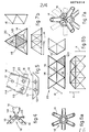
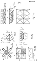
- Figs.1 show some shapes of the device of the invention.
- Said device 10 comprises a substantially quadrangular middle area 11, in relation to which four other perimetric areas 12 are sloped at 45°.
- Each of the four perimetric areas 12 comprises one or more through holes 13, which have the same distances between their centres as those between the centres of the holes 113 in the ends 114 of the rods 14 (see Fig.3a).
- the middle area 11 of the device may comprise, or not, a central through hole 15, which may be surrounded, or not, by a strengthening ring 115 (Fig.2a).
- the perimetric profile of the device 10 and the number and lay-out of the holes 13 in the perimetric areas 12 can vary and there will correspondingly be the same variations as regards the holes 113 in the ends 114 of the rods 14 as well.
- Figs.2a and 2b respectively show two nodal junctions 16-116 which can be obtained with two forms of the device of the invention. Said nodal junctions 16-116 have a shape substantially comparable to a cube.
- Fig.3a shows a detail of a blade-wise end 114 of a tubular rod 14.
- said ends 114 are flattened so as to obtain the blade-wise profile desired.
- the holes 113 to secure the rod 14 can be clearly seen.
- the rod 14 is shown in Fig.3b with its ends 114 coplanar in this instance.
- One (or more) hole 17 is comprised near the end 114 of the rod 14 for the passage of galvanising metal inwards (Fig.3a).
- the ends can be conformed also as in Fig.3c, thereby obviating the hole on the outer surface near the end 114. In this way the galvanising metal will enter through the holes 17 made in the end itself.
- Fig.4 shows diagrammatically a possible connection between devices 10 of a nodal junction 16 and a rod 14.
- said connection is made with bolts 22 but could be made with rivets, when so wished, or by welding.
- the ends 114 of a rod may not lie on the same plane as each other (see Fig.14); this enables hyperbolic paraboloid grills 19 to be constructed (see Fig.15).
- Fig.6a shows a nodal junction 16 made with devices of the invention in a view which gives the spatial position of said nodal junction 16 as comprised in the spatial structure or grill 20 of Fig.6b, where a nodal junction 16 oriented and having its rods positioned as in Fig.6a is indicated with an arrow.
- Fig.7a shows a nodal junction 16 according to the orientation of the nodal junction indicated with an arrow in Fig.7b.
- the tetrahedral arrangement which can be obtained by the invention for the grill 20 should be noted.
- the plan of the grills 20 of Figs.6 and 7 comprises a triangular module 120.
- Fig.8b shows, instead, a grill 21 with a quadrangular module 121.
- the relative orientation of the nodal junction 16 indicated with the arrow is shown in Fig.8a.
- Figs.9 and 10 show the possibility of varying the height of grills formed according to the invention by employing rods of two different sizes. This is made possible because the axis of each rod 14 lies on a plane which contains the corner of the nodal junction-cube and internal diagonal and which can rotate around the axis of the anchorage bolt 22 perpendicular to said plane.
- the device 10 will have an edge such as to enable the rod to be secured in directions which are different but which always belong to a plane of rotation of which the axis is the assembly bolt 22.
- the ends 114 of the rod will have corresponding through holes 113 with the direction of the line between centres of said holes suitably sloped (angle 18 of Fig.5) and depending on the ratio assumed in Fig.9 between the size M of the rod of the basic triangular module 20 and the size of the other three rods.
- a greater or lesser thickness H is also determined in the grill 21 with a quadrangular module 121, as shown in a side view in Fig.11b.
- the grill with a square module will take up the form of a rectangular module (Figs.11a and 11c), of which the two sizes will be those derived from Fig.9, account being taken of the fact that the nature of the module 120 or 121 depends on the pre-selected orientation of the nodal junctions, or,, in other words, on the fact that the basic plane of the grill contains a triangular module 120 or a quadrangular module 121.
- Assembly of the grill of the invention can be performed cantilever-wise by making use of a movable scaffold, or else, if space is available on the building site, it is possible to fit together whole grill elements on the ground and then hoist them and put them in their final position by means of sclf- propelled cranes or other like lifting means. Said two procedures can be readily combined to suit the circumstances.
- Fig.12 shows a possible connection between the ends of rods, which in this instance have an open profile 23 (I-sections, H-sections, etc.), and devices 10 forming a nodal junction 16.
- Said rods can also be of another type.
- connection between rod 23 and device 10 is made by welding.
- the sizes and dimensions of the rods 23, normally having an open profile, and of the nodal junctions 16 may vary in every way, depending on the design.
- the rod normally having an open profile, can be pre-arranged, before being fitted, with a device 10 connected to each of its ends.
- the rods 24 can be provided with holes 117 variously arranged for the passage and/or anchorage of elements of equipment on the structure.
- Fig.14 shows a rod 14 with blade-wise ends 114 which are not coplanar. In this way it is possible to form hyperbolic paraboloid grills 19 (Fig.15) wherein the orientation of the nodal junctions 16 varies continuously along the structure.
- Fig.16 shows a build-up 25 of tetrahedra and semi-octahedra forming part of a grill 20-21 according to the invention. Said build-up 25 is seen in this instance as an octahedron-cube.
- the quadrangular module 121 here square, is obtained with this build-up 25 by reference to a section plane parallel to one face of the cube 26 drawn with dashes in the figure, and the triangular module 120 is obtained by reference to a section plane equally inclined in relation to three faces of the cube 26 with a common vertex 126.
Landscapes
- Engineering & Computer Science (AREA)
- Architecture (AREA)
- Physics & Mathematics (AREA)
- Electromagnetism (AREA)
- Civil Engineering (AREA)
- Structural Engineering (AREA)
- Joining Of Building Structures In Genera (AREA)
Applications Claiming Priority (2)
| Application Number | Priority Date | Filing Date | Title |
|---|---|---|---|
| IT64812/81A IT1221109B (it) | 1981-10-21 | 1981-10-21 | Dispositivo di giunzione particolarmente per griglie di copertura e per sistemi cubici antisismici |
| IT6481281 | 1981-10-21 |
Publications (1)
| Publication Number | Publication Date |
|---|---|
| EP0079314A1 true EP0079314A1 (de) | 1983-05-18 |
Family
ID=11297256
Family Applications (1)
| Application Number | Title | Priority Date | Filing Date |
|---|---|---|---|
| EP82830258A Withdrawn EP0079314A1 (de) | 1981-10-21 | 1982-10-15 | Verbindungsvorrichtung für netzförmige Raumstrukturen und solche Vorrichtungen verwendende netzförmige Strukturen |
Country Status (2)
| Country | Link |
|---|---|
| EP (1) | EP0079314A1 (de) |
| IT (1) | IT1221109B (de) |
Cited By (13)
| Publication number | Priority date | Publication date | Assignee | Title |
|---|---|---|---|---|
| WO1987001150A1 (en) * | 1985-08-16 | 1987-02-26 | Garry Randall Hart | Adjustable space frames |
| FR2592922A1 (fr) * | 1986-01-13 | 1987-07-17 | Doat Olivier | Element de liaison entre des profiles pour realiser des structures tridimensionnelles. |
| EP0307718A1 (de) * | 1987-09-18 | 1989-03-22 | QUATTROCCHIO S.r.L. | Modulare Fachwerkkonstruktion |
| US5435110A (en) * | 1993-08-04 | 1995-07-25 | Aluminum Company Of America | Method of joining of hollow framework and associated frame assembly |
| WO1996028621A1 (de) * | 1995-03-15 | 1996-09-19 | Burkhardt Leitner | Verbindungselement |
| EP1538269A1 (de) * | 2003-12-01 | 2005-06-08 | Münch GmbH | System zur Herstellung eines Stabwerks |
| US6920724B1 (en) * | 2001-01-04 | 2005-07-26 | Epic Metals Corporation | Bracket for a structural panel and a structural panel made with such a bracket |
| AT500438B1 (de) * | 2004-05-03 | 2009-01-15 | Waagner Biro Stahlbau Ag | Knoten zum verbinden von stäben eines flächentragwerks |
| ITUD20110137A1 (it) * | 2011-08-30 | 2013-03-01 | Dino Merlo | Nodo strutturale per costruzioni edili |
| DE102013005212A1 (de) * | 2013-03-27 | 2014-10-16 | Vitalis Jung | Einrichtung zum Verbinden von mindestens zwei Bauteilen |
| CN109162348A (zh) * | 2018-10-17 | 2019-01-08 | 苏州昆仑绿建木结构科技股份有限公司 | 一种带预应力增强箱梁的装配式竹空心框架结构 |
| CN113152666A (zh) * | 2021-04-21 | 2021-07-23 | 青岛理工大学 | 自拉结钢木组合节点及安装方法 |
| CN116950220A (zh) * | 2023-04-21 | 2023-10-27 | 北京市建筑设计研究院有限公司 | 一种新型装配节点及设计方法 |
Citations (5)
| Publication number | Priority date | Publication date | Assignee | Title |
|---|---|---|---|---|
| FR1280634A (fr) * | 1960-11-21 | 1962-01-08 | élément pour structures métalliques | |
| US3563580A (en) * | 1967-10-16 | 1971-02-16 | Anthony Frederick Black | Frame joint |
| DE2116707B1 (de) * | 1971-04-06 | 1972-06-08 | Wurgarohr GmbH, 5757 Wickede | Knotenpunktverbindung für zerlegbare Fachwerkkonstruktionen |
| FR2386714A1 (fr) * | 1977-04-08 | 1978-11-03 | Nasi Cesarino | Dispositif pour la realisation de noeuds d'assemblage pour structures spatiales, et structures ainsi realisees |
| GB2014685A (en) * | 1978-02-17 | 1979-08-30 | Jeannin J L | Connector for space frames |
-
1981
- 1981-10-21 IT IT64812/81A patent/IT1221109B/it active
-
1982
- 1982-10-15 EP EP82830258A patent/EP0079314A1/de not_active Withdrawn
Patent Citations (5)
| Publication number | Priority date | Publication date | Assignee | Title |
|---|---|---|---|---|
| FR1280634A (fr) * | 1960-11-21 | 1962-01-08 | élément pour structures métalliques | |
| US3563580A (en) * | 1967-10-16 | 1971-02-16 | Anthony Frederick Black | Frame joint |
| DE2116707B1 (de) * | 1971-04-06 | 1972-06-08 | Wurgarohr GmbH, 5757 Wickede | Knotenpunktverbindung für zerlegbare Fachwerkkonstruktionen |
| FR2386714A1 (fr) * | 1977-04-08 | 1978-11-03 | Nasi Cesarino | Dispositif pour la realisation de noeuds d'assemblage pour structures spatiales, et structures ainsi realisees |
| GB2014685A (en) * | 1978-02-17 | 1979-08-30 | Jeannin J L | Connector for space frames |
Cited By (16)
| Publication number | Priority date | Publication date | Assignee | Title |
|---|---|---|---|---|
| GB2199865A (en) * | 1985-08-16 | 1988-07-20 | Garry Randall Hart | Adjustable space frames |
| GB2199865B (en) * | 1985-08-16 | 1989-09-06 | Garry Randall Hart | Adjustable space frames |
| WO1987001150A1 (en) * | 1985-08-16 | 1987-02-26 | Garry Randall Hart | Adjustable space frames |
| FR2592922A1 (fr) * | 1986-01-13 | 1987-07-17 | Doat Olivier | Element de liaison entre des profiles pour realiser des structures tridimensionnelles. |
| EP0307718A1 (de) * | 1987-09-18 | 1989-03-22 | QUATTROCCHIO S.r.L. | Modulare Fachwerkkonstruktion |
| AU595137B2 (en) * | 1987-09-18 | 1990-03-22 | Quattrocchio S.R.L. | Modular latticework structure |
| US5435110A (en) * | 1993-08-04 | 1995-07-25 | Aluminum Company Of America | Method of joining of hollow framework and associated frame assembly |
| WO1996028621A1 (de) * | 1995-03-15 | 1996-09-19 | Burkhardt Leitner | Verbindungselement |
| US6920724B1 (en) * | 2001-01-04 | 2005-07-26 | Epic Metals Corporation | Bracket for a structural panel and a structural panel made with such a bracket |
| EP1538269A1 (de) * | 2003-12-01 | 2005-06-08 | Münch GmbH | System zur Herstellung eines Stabwerks |
| AT500438B1 (de) * | 2004-05-03 | 2009-01-15 | Waagner Biro Stahlbau Ag | Knoten zum verbinden von stäben eines flächentragwerks |
| ITUD20110137A1 (it) * | 2011-08-30 | 2013-03-01 | Dino Merlo | Nodo strutturale per costruzioni edili |
| DE102013005212A1 (de) * | 2013-03-27 | 2014-10-16 | Vitalis Jung | Einrichtung zum Verbinden von mindestens zwei Bauteilen |
| CN109162348A (zh) * | 2018-10-17 | 2019-01-08 | 苏州昆仑绿建木结构科技股份有限公司 | 一种带预应力增强箱梁的装配式竹空心框架结构 |
| CN113152666A (zh) * | 2021-04-21 | 2021-07-23 | 青岛理工大学 | 自拉结钢木组合节点及安装方法 |
| CN116950220A (zh) * | 2023-04-21 | 2023-10-27 | 北京市建筑设计研究院有限公司 | 一种新型装配节点及设计方法 |
Also Published As
| Publication number | Publication date |
|---|---|
| IT8164812A0 (it) | 1981-10-21 |
| IT1221109B (it) | 1990-06-21 |
Similar Documents
| Publication | Publication Date | Title |
|---|---|---|
| CA2566328C (en) | Two-way architectural structural system and modular support member | |
| EP0079314A1 (de) | Verbindungsvorrichtung für netzförmige Raumstrukturen und solche Vorrichtungen verwendende netzförmige Strukturen | |
| US5129203A (en) | Building panel core | |
| EP2802717B1 (de) | Fachwerkstruktur mit mehreren innovativen verbindungen für dachdeckungszwecke | |
| US6701691B1 (en) | Dome constructing method | |
| US4637192A (en) | Telescoping support structure | |
| US6318043B1 (en) | Shelter and shelter support members | |
| US10501956B2 (en) | Hurricane, tornado, flood, storm surge, forest fire and mud slide resistant house | |
| CN110777938A (zh) | 一种在钢桁架中增设预应力钢拉索的悬挂结构 | |
| US6938391B1 (en) | Structural member | |
| CN1727617A (zh) | 一种观光标志塔 | |
| CN223003605U (zh) | 一种大跨度柔性支撑屋盖 | |
| CN218815609U (zh) | 帐篷结构组件 | |
| CN111962731A (zh) | 网格梁加双向受力的钢筋桁架楼板结构及其施工方法 | |
| US7500333B2 (en) | JPH building | |
| Irfan et al. | Assessment of behavior of steel space frames with two-way orthogonal latticed grids and orthogonal square pyramid space grids | |
| JPH0223684Y2 (de) | ||
| MITSUDA | Structural design of a gymnasium with warren trusses in a grid arrangement supported by thin columns and damping braces | |
| Makowski | Modern grid structures | |
| Valencia | Recent aluminum roof structures in Colombia | |
| Okayama et al. | Structural Design of Two buildings with Large Spaces | |
| NZ299662A (en) | Adjustable height building pile or pier comprises cap engageable with end of hollow post and nut on central shaft | |
| Noble | Spaceframes: Diversity and Flexibility | |
| WO1990010762A1 (en) | A space frame | |
| DeGanyar et al. | Space-frame pyramid |
Legal Events
| Date | Code | Title | Description |
|---|---|---|---|
| PUAI | Public reference made under article 153(3) epc to a published international application that has entered the european phase |
Free format text: ORIGINAL CODE: 0009012 |
|
| AK | Designated contracting states |
Designated state(s): AT BE CH DE FR GB LI LU NL SE |
|
| 18W | Application withdrawn |
Withdrawal date: 19830930 |
|
| 17P | Request for examination filed |
Effective date: 19840118 |
|
| D18W | Application withdrawn (deleted) | ||
| R17P | Request for examination filed (corrected) |
Effective date: 19840118 |
|
| STAA | Information on the status of an ep patent application or granted ep patent |
Free format text: STATUS: THE APPLICATION IS DEEMED TO BE WITHDRAWN |
|
| 18D | Application deemed to be withdrawn |
Effective date: 19870501 |