EP0079433A1 - Zentrifugalpumpe - Google Patents
Zentrifugalpumpe Download PDFInfo
- Publication number
- EP0079433A1 EP0079433A1 EP82107809A EP82107809A EP0079433A1 EP 0079433 A1 EP0079433 A1 EP 0079433A1 EP 82107809 A EP82107809 A EP 82107809A EP 82107809 A EP82107809 A EP 82107809A EP 0079433 A1 EP0079433 A1 EP 0079433A1
- Authority
- EP
- European Patent Office
- Prior art keywords
- pump
- outlet port
- pump runner
- runner
- casing
- Prior art date
- Legal status (The legal status is an assumption and is not a legal conclusion. Google has not performed a legal analysis and makes no representation as to the accuracy of the status listed.)
- Granted
Links
- 239000012530 fluid Substances 0.000 claims abstract description 62
- 230000004907 flux Effects 0.000 claims abstract description 49
- 238000004519 manufacturing process Methods 0.000 claims abstract description 9
- 230000006872 improvement Effects 0.000 claims description 7
- 238000010276 construction Methods 0.000 description 13
- 238000012856 packing Methods 0.000 description 9
- 238000005266 casting Methods 0.000 description 8
- 239000000306 component Substances 0.000 description 7
- XLYOFNOQVPJJNP-UHFFFAOYSA-N water Substances O XLYOFNOQVPJJNP-UHFFFAOYSA-N 0.000 description 6
- 238000003754 machining Methods 0.000 description 4
- 210000004907 gland Anatomy 0.000 description 3
- 230000002452 interceptive effect Effects 0.000 description 3
- 239000000463 material Substances 0.000 description 3
- 238000005192 partition Methods 0.000 description 3
- 229910001018 Cast iron Inorganic materials 0.000 description 2
- 238000009826 distribution Methods 0.000 description 2
- 230000000694 effects Effects 0.000 description 2
- 230000009467 reduction Effects 0.000 description 2
- 239000004576 sand Substances 0.000 description 2
- 238000001816 cooling Methods 0.000 description 1
- 238000005520 cutting process Methods 0.000 description 1
- 238000000034 method Methods 0.000 description 1
- 230000000149 penetrating effect Effects 0.000 description 1
- 230000037452 priming Effects 0.000 description 1
- 230000008569 process Effects 0.000 description 1
- 238000003908 quality control method Methods 0.000 description 1
- 230000001105 regulatory effect Effects 0.000 description 1
- 238000009877 rendering Methods 0.000 description 1
- 238000007789 sealing Methods 0.000 description 1
Images




Classifications
-
- F—MECHANICAL ENGINEERING; LIGHTING; HEATING; WEAPONS; BLASTING
- F04—POSITIVE - DISPLACEMENT MACHINES FOR LIQUIDS; PUMPS FOR LIQUIDS OR ELASTIC FLUIDS
- F04D—NON-POSITIVE-DISPLACEMENT PUMPS
- F04D29/00—Details, component parts, or accessories
- F04D29/40—Casings; Connections of working fluid
- F04D29/42—Casings; Connections of working fluid for radial or helico-centrifugal pumps
- F04D29/44—Fluid-guiding means, e.g. diffusers
-
- F—MECHANICAL ENGINEERING; LIGHTING; HEATING; WEAPONS; BLASTING
- F04—POSITIVE - DISPLACEMENT MACHINES FOR LIQUIDS; PUMPS FOR LIQUIDS OR ELASTIC FLUIDS
- F04D—NON-POSITIVE-DISPLACEMENT PUMPS
- F04D29/00—Details, component parts, or accessories
- F04D29/40—Casings; Connections of working fluid
- F04D29/42—Casings; Connections of working fluid for radial or helico-centrifugal pumps
- F04D29/44—Fluid-guiding means, e.g. diffusers
- F04D29/445—Fluid-guiding means, e.g. diffusers especially adapted for liquid pumps
-
- F—MECHANICAL ENGINEERING; LIGHTING; HEATING; WEAPONS; BLASTING
- F04—POSITIVE - DISPLACEMENT MACHINES FOR LIQUIDS; PUMPS FOR LIQUIDS OR ELASTIC FLUIDS
- F04D—NON-POSITIVE-DISPLACEMENT PUMPS
- F04D29/00—Details, component parts, or accessories
- F04D29/40—Casings; Connections of working fluid
- F04D29/42—Casings; Connections of working fluid for radial or helico-centrifugal pumps
- F04D29/426—Casings; Connections of working fluid for radial or helico-centrifugal pumps especially adapted for liquid pumps
- F04D29/428—Discharge tongues
Definitions
- This invention relates to a centrifugal pump of improved construction having improved pump performance.
- the invention has been developed for the purpose of obviating the aforesaid problem of the prior art. Accordingly the invention has as its object the provision of a centrifugal pump of improved construction capable of obtaining increased pump performance.
- the outstanding characteristic of the invention enabling the aforesaid object to be accomplished is that at least one deflecting wall is mounted in the vicinity of an inlet of the volute chamber to cause a return flow of a fluid flux flowing toward an outlet port of the pump runner along an inner wall surface of the volute chamber to be deflected to avoid production therein of a velocity component flowing in counter current to a flow of a fluid flux discharged from the pump runner, to thereby prevent the returning fluid flux from interfering with the fluid flow discharged from the outlet port of the pump runner.
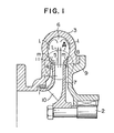
- a surface lla of the deflecting walls 11 on the pump runner 1 extends toward the outlet port 5 of the pump runner 1 with a small clearance between it and the end faces 12 of the front shroud 4 and rear shroud 5, and a surface llb of the deflecting walls 11 on the side of the volute chamber 6 extends toward the outlet port 5 of the pump runner 1 in a manner to be substantially perpendicular to the direction of flow of a fluid flux L discharged through the outlet port 5 of the pump runner 1.
- fluid drawn by suction through an inlet port 10 of the pump runner 1 is discharged into the volute chamber 6 through the outlet port 5 of the pump runner 1.
- the fluid discharged into the volute chamber 6 has the direction of its flow changed therein, so that a portion of the fluid becomes a fluid flux & flowing along the inner wall surface of the volute chamber 6 toward the vicinity of the inlet of the volute chamber 6.
- the fluid flox flowing along the inner wall surface of the volute chamber 6 has its direction of flow altered along the surface llb of the deflecting walls 11 contiguous with the inner wall surface of the volute chamber 6, so that it becomes a fluid flux m directed toward the outlet port 5 of the pump runner 1.
- the fluid flux m After intersecting the fluid flux L from the outlet port 5 of the pump runner 1 along the surface llb of the deflecting walls 11 substantially perpendicularly thereto, the fluid flux m is fed into the volute chamber 6 along with the fluid flux L because the fluid flux L is absolutely greater in volume than the fluid flux m. At this time, the fluid flux m has no velocity component (oriented in the direction n in Fig. 2) in counter current to the direction of the fluid flux L, so that the flow of the fluid flux L is not interfered with. In this way, direct confrontation of the fluid flux m flowing in return flow along the inner wall surface of the volute chamber 6 with the fluid flux L discharged through the outlet port 5 of the pump runner 1 is avoided to eliminate the risk of development of an eddy current.
- the fluid flux t flowing in return flow along the inner wall surface of the volute chamber 6 is prevented from interfering with the outflow of the fluid flux L discharged through the outlet port 5 of the pump runner 1.
- the pump performs in the same manner as if there were no axial movement of the pump runner 1, even if the pump runner 1 moves axially during operation. More speciai- cally, a reduction in eddy loss and disc friction loss causes a rise in the discharge pressure of the centrifugal pump and an increase in the flow rate of fluid delivered by the pump while reducing an axial drive force, to thereby increase the efficiency of the pump.
- 13 is a deflecting wall extending from the casing cover 9 toward the outlet port 5 of the pump runner 1 and arranged, like the deflecting walls 11 described by referring to Figs. 1 and 2, annularly with a small clearance between it and the end face of the rear shroud 7 of the pump runner 1 on the outlet side.
- the surface of the deflecting wall 11 on the side of the volute chamber 6 is contiguous with the inner surface of the casing 3 and constructed such that its extended surface is substantially perpendicular to the direction of flow of the fluid flux L discharged from the pump runner 1, to prevent a velocity component counter current to the fluid flux L from being produced in the fluid flux m returning along the inner wall surface of the volute chamber 6 toward the outlet port 5 of the pump runner 1.
- the pump runner 1 When the parts are assembled, the pump runner 1 is assembled with the casing cover 9, and the casing 3 is assembled with the casing cover 9 after making sure that the pump runner 1 and the deflecting wall 11 is in correct positional relation.
- This enables quality control of a centrifugal pump to be carried out by a simple process.
- the use of this construction enables assembling of the pump runner 1 having an outlet port 5 of a different width to be effected with the casing cover 9 by merely altering the dimensions of the casing cover 9 to be machined, allowing realization of benefits from common use of parts to be achieved.
- the deflecting walls for deflecting a fluid flux returning along the inner wall surface of the volute chamber toward the outlet port of the pump runner to avoid production therein of a velocity component flowing in counter current to a fluid flux discharged through the outlet port of the pump runner are in the form of tubues and mounted in the vicinity of the inlet of the volute chamber.
- the pump runner 1 is enclosed by a casing 3 defining a volute chamber 4, a casing cover 16 located on the side of a front shroud 4 and a casing cover 9 located on the side of a rear shroud 7.
- deflecting walls 14 and 15 are deflecting walls in the form of tubues including large thickness portions 14a and 15a.
- the deflecting wall 14 is held in position while its large thickness portion 14a is held between the casing 3 and casing cover 16, and the deflecting wall 15 is likewise held in position while its large thickness portion 15a is held between the casing 3 and casing cover 9.
- a suitable dimension may be selected for small thickness portions 14b and 15b of the deflecting walls 14 and 15 in such a manner that they will be arranged on the side of the end face of the pump runner 1 on its discharge side when the centrifugal pump is assembled.
- the small thickness portions 14b and 15b are contiguous at their surfaces facing the volute chamber 6 with the inner wall surface of the casing 3 and located substantially perpendicular to a fluid flux discharged from the pump runner 1.
- the direction in which fluid is discharged therefrom is substantially perpendicular to the rotary shaft 2, so that the surfaces of the small thickness portions 14b and 15b of the deflecting walls 14 and 15 on the side of the volute chamber 6 should be substantially parallel to the rotary shaft 2.
- the deflecting walls are formed of other material than the materials forming the casing 3 and casing cover 9, replacements of the old deflecting walls 14 and 15 by new ones can be readily effected when wear is caused thereon.
- volute chamber 6 in the casi:g 3 is extended toward the side of the front shroud 4 ii. which the flow of fluid discharged from the pump rur:er 1 has a lower velocity.
- the flow L 1 regains pressure and has its velocity reduced within the volute chamber 6, so that it does not interfere with the flow L 2 of lower velocity discharged and located on the side of the front shroud 4.
- This construction can eliminate head-on collision between the flow L 1 of higher velocity and the flow L 2 of lower velocity, thereby reducing a loss of mixing in the volute chamber 6 and improving pump performance.
- the deflecting walls 11 achieve the same effects as described by referring to the embodiments shown in Figs. 1-5, so that the description thereof shall be omitted.
- two deflecting walls are provided in the vicinity of the inlet of the volute chamber in positions corresponding to the end faces of the front shroud and the rear shroud.
- the invention is not limited to this specific number of deflecting walls and one of the deflecting walls may be provided on one side of the vicinity of the inlet of the volute chamber in a position facing the end face of the front shroud or the rear shroud.
- the forward end of each deflecting wall (the end face on the side of the outlet port of the pump runner) is extended to a point immediately before it faces the outlet port.
- the deflecting walls may be shaped such that the spacing between the end faces of the deflecting walls is greater than the diameter of the outlet port of the pump runner.
- the surfaces of the deflecting walls facing the volute chamber are cylindrical in shape and substantially parallel to the rotary shaft.
- the deflecting walls may be constructed such that their forward ends are slightly inclined toward the center of the volute chamber.
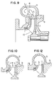
- Figs. 10-14 show other embodiments.
- the spacing W between the deflecting walls 11 is greater than the inner diameter of the outlet port 5 of the pump runner 1 and smaller than the outer diameter thereof.
- the deflecting wall 11 formed on the side of the casing 3 is located substantially flush with the end face 12 of the outlet port 5 on the side of the front shroud 4.
- the deflecting wall 11 is formed on the casing 3 only on the side of the front shroud 4.
- the deflecting walls 11 extend along the vicinity of extensions of the end faces 12 of the outlet port 5 near the front and rear shrouds 4 and 7 and are juxtaposed against the front and rear shrouds 4 and 7 respectively.
- FIG. 15-18 An embodiment of the invention shown in concrete form is shown in Figs. 15-18, wherein parts similar to those shown in Figs. 1-14 are designated by like reference characters and their description is omitted.
- 3b, 3c and 3d are a base, a suction flange and a discharge flange respectively which are integrally formed with the casing 3 by casting.
- the two flanges 3c and 3d have mounting ducts 17 and 18 for a gauge and a priming water funnel respectively formed at the back of Fig. 15.
- a duct 19 is formed starting at the vicinity of the lowermost portion of the volute chamber 6 in the casing 3 and extending toward the convolution starting side (back of Fig. 15) of the volute chamber 6.
- 20 is a duct for mounting a gauge extending axially of the discharge flange 3d.
- 21 is a liner ring secured to the casing 3
- 22 is an 0-ring held between the spigot joint surface 3a of the casing 3 and the spigot joint surface 9a of the casing cover 9 for the casing 3.
- 23 is a bearing box having one end positioned against the casing cover 9, a central portion supporting a main bearing 24 and another end having attached thereto a bracket 26 supporting an auxiliary bearing 25.
- the bearing box 23 is bolted at 27 to the casing 3 in a manner to hold the casing cover 9 between it and the casing 3.
- a partition wall 28 is located on the side of the casing 3 with respect to the main bearing 24 in the central portion of the bearing box 23.
- a ventilating passageway 30 is defined partly between an outer race of the main bearing 24 and an inner wall surface of the bearing box 23. 29 is a slinger mounted on the rotary shaft 2 outside of the partition wall 28. 31 designates bolts for affixing to an end portion of the bearing box 23 the bracket 26 supporting the outer race of the auxiliary bearing 25.
- the main bearing 24 has a larger diameter and a greater capacity than the auxiliary bearing 25.
- a spigot joint surface 26a for mounting the bracket 26 or the inner wall surface of the bearing box 23 are larger than the outer diameter of the main bearing 24.
- 23a is an opening formed in the bearing box 23.
- 32 is a square packing for effecting shaft sealing.
- 33 is a cylindrical cavity formed in the central portion of the casing cover 9 for housing the square packing 32.
- 34 is a packing gland for arranging the square packing 32 inside the cavity 33.
- 35 is a bolt for threadable engagement with the casing cover 9 for biasing the packing gland 34 toward the casing cover 9 to affix same thereto.
- 37 is a nut for mounting the pump runner 1 on the end of the rotary shaft 2 which is brought into threadable engagement with a screw thread, not shown, formed at the end of the rotary shaft 2 with a washer 36 interposed therebetween.
- 38 is an ancillary leg secured to a lower portion of the bearing box 23.
- the casing 3 is arranged in position against the casing cover 9, and the casing 3 is secured to the bearing box 23 by the bolts 27 in such a manner that the casing cover 9 is held by the casing 3 and the bearing box 23. Finally the bolts 27 and nuts are tightened to provide a completed centrifugal pump.
Landscapes
- Engineering & Computer Science (AREA)
- Mechanical Engineering (AREA)
- General Engineering & Computer Science (AREA)
- Structures Of Non-Positive Displacement Pumps (AREA)
Applications Claiming Priority (2)
| Application Number | Priority Date | Filing Date | Title |
|---|---|---|---|
| JP182261/81 | 1981-11-16 | ||
| JP56182261A JPS5885398A (ja) | 1981-11-16 | 1981-11-16 | うず巻ポンプ |
Publications (2)
| Publication Number | Publication Date |
|---|---|
| EP0079433A1 true EP0079433A1 (de) | 1983-05-25 |
| EP0079433B1 EP0079433B1 (de) | 1988-01-07 |
Family
ID=16115152
Family Applications (1)
| Application Number | Title | Priority Date | Filing Date |
|---|---|---|---|
| EP82107809A Expired EP0079433B1 (de) | 1981-11-16 | 1982-08-25 | Zentrifugalpumpe |
Country Status (4)
| Country | Link |
|---|---|
| EP (1) | EP0079433B1 (de) |
| JP (1) | JPS5885398A (de) |
| KR (1) | KR880001488B1 (de) |
| DE (1) | DE3277927D1 (de) |
Cited By (3)
| Publication number | Priority date | Publication date | Assignee | Title |
|---|---|---|---|---|
| GB2226364A (en) * | 1988-12-24 | 1990-06-27 | Skf Gmbh | Pumping chamber arrangement |
| GB2250059A (en) * | 1990-10-02 | 1992-05-27 | Zanussi Elettrodomestici | Circulating pump for dishwashers |
| CN114667396A (zh) * | 2019-11-25 | 2022-06-24 | 罗伯特·博世有限公司 | 分离装置和具有分离装置的流体机械 |
Families Citing this family (6)
| Publication number | Priority date | Publication date | Assignee | Title |
|---|---|---|---|---|
| JPS61147398U (de) * | 1985-03-06 | 1986-09-11 | ||
| JP4959424B2 (ja) * | 2007-05-31 | 2012-06-20 | 勇 青谷 | ポンプ装置 |
| JP6671048B2 (ja) * | 2015-11-12 | 2020-03-25 | パナソニックIpマネジメント株式会社 | ポンプ |
| KR101893847B1 (ko) * | 2016-11-11 | 2018-08-31 | 명화공업주식회사 | 워터펌프 |
| KR102159625B1 (ko) * | 2020-01-20 | 2020-09-25 | (주)신한펌프테크 | 트윈캡형 펌프 |
| CN111486099B (zh) * | 2020-05-25 | 2025-09-23 | 谱罗顿智能泵业(安徽)有限公司 | 一种旋涡式自吸电泵的泵体及其泵送方法 |
Citations (1)
| Publication number | Priority date | Publication date | Assignee | Title |
|---|---|---|---|---|
| CH428444A (de) * | 1965-02-13 | 1967-01-15 | Volland Georg Ing Dr | Kreiselpumpe mit Selbstansaugung nach dem Prinzip der Laufradzellenspülung |
Family Cites Families (1)
| Publication number | Priority date | Publication date | Assignee | Title |
|---|---|---|---|---|
| JPS4513966Y1 (de) * | 1967-06-24 | 1970-06-13 |
-
1981
- 1981-11-16 JP JP56182261A patent/JPS5885398A/ja active Pending
-
1982
- 1982-08-25 DE DE8282107809T patent/DE3277927D1/de not_active Expired
- 1982-08-25 EP EP82107809A patent/EP0079433B1/de not_active Expired
- 1982-08-30 KR KR8203904A patent/KR880001488B1/ko not_active Expired
Patent Citations (1)
| Publication number | Priority date | Publication date | Assignee | Title |
|---|---|---|---|---|
| CH428444A (de) * | 1965-02-13 | 1967-01-15 | Volland Georg Ing Dr | Kreiselpumpe mit Selbstansaugung nach dem Prinzip der Laufradzellenspülung |
Cited By (5)
| Publication number | Priority date | Publication date | Assignee | Title |
|---|---|---|---|---|
| GB2226364A (en) * | 1988-12-24 | 1990-06-27 | Skf Gmbh | Pumping chamber arrangement |
| GB2226364B (en) * | 1988-12-24 | 1992-10-28 | Skf Gmbh | Liquid pump |
| GB2250059A (en) * | 1990-10-02 | 1992-05-27 | Zanussi Elettrodomestici | Circulating pump for dishwashers |
| CN114667396A (zh) * | 2019-11-25 | 2022-06-24 | 罗伯特·博世有限公司 | 分离装置和具有分离装置的流体机械 |
| CN114667396B (zh) * | 2019-11-25 | 2025-07-01 | 罗伯特·博世有限公司 | 分离装置和具有分离装置的流体机械 |
Also Published As
| Publication number | Publication date |
|---|---|
| KR880001488B1 (ko) | 1988-08-13 |
| KR840001306A (ko) | 1984-04-30 |
| JPS5885398A (ja) | 1983-05-21 |
| DE3277927D1 (en) | 1988-02-11 |
| EP0079433B1 (de) | 1988-01-07 |
Similar Documents
| Publication | Publication Date | Title |
|---|---|---|
| CA1160507A (en) | Pumps | |
| US3704075A (en) | Combined turbine nozzle and bearing frame | |
| US5088889A (en) | Seal for a flow machine | |
| US4642030A (en) | Arrangement for feeding fuel from supply tank | |
| EP0079433A1 (de) | Zentrifugalpumpe | |
| US4793777A (en) | Centrifugal pump with auxiliary impeller operatively associated with a primary impeller to balance the forces on the opposite sides thereof | |
| EP0442884B1 (de) | Turbolader | |
| US4022423A (en) | Control valve | |
| CA2046983C (en) | Centrifugal pumps | |
| US4545730A (en) | Liquid ring vacuum pump for gaseous media | |
| US3253816A (en) | De-aeration of sealing fluid in aerated rotary fluid machines | |
| GB1387480A (en) | Energy transfer machine | |
| EP0086151B1 (de) | Dichtung für Pumpen | |
| CZ233894A3 (en) | Gas pump with a fluid ring | |
| FI74780C (fi) | Axiellt instaellbart pumphjul vid centrifugalpump. | |
| CA1215268A (en) | Sealing of a shaft in a centrifugal pump and a method for effecting the sealing | |
| US7946828B2 (en) | Screw type liquid ring pump with shaft seal arrangement | |
| KR850000352B1 (ko) | 유체순환용 축류(軸流)원심펌프 | |
| US5527150A (en) | Regenerative pumps | |
| EP0159968A2 (de) | Schieberzellenluftpumpe mit aus Blech gestampftem Gehäuse | |
| US4118800A (en) | Device for use in beating or refining machines | |
| US4127369A (en) | Pressure valve for a rotary piston compressor | |
| JPH08557Y2 (ja) | ポンプ軸封部の冷却構造 | |
| JPS55128695A (en) | Centrifugal pump | |
| US2810346A (en) | Shallow well pump |
Legal Events
| Date | Code | Title | Description |
|---|---|---|---|
| PUAI | Public reference made under article 153(3) epc to a published international application that has entered the european phase |
Free format text: ORIGINAL CODE: 0009012 |
|
| AK | Designated contracting states |
Designated state(s): DE GB IT |
|
| 17P | Request for examination filed |
Effective date: 19830920 |
|
| GRAA | (expected) grant |
Free format text: ORIGINAL CODE: 0009210 |
|
| AK | Designated contracting states |
Kind code of ref document: B1 Designated state(s): DE GB IT |
|
| REF | Corresponds to: |
Ref document number: 3277927 Country of ref document: DE Date of ref document: 19880211 |
|
| ITF | It: translation for a ep patent filed | ||
| PLBI | Opposition filed |
Free format text: ORIGINAL CODE: 0009260 |
|
| 26 | Opposition filed |
Opponent name: KSB AKTIENGESELLSCHAFT Effective date: 19881006 |
|
| RDAG | Patent revoked |
Free format text: ORIGINAL CODE: 0009271 |
|
| STAA | Information on the status of an ep patent application or granted ep patent |
Free format text: STATUS: PATENT REVOKED |
|
| 27W | Patent revoked |
Effective date: 19890916 |
|
| GBPR | Gb: patent revoked under art. 102 of the ep convention designating the uk as contracting state |