EP0079434A1 - Store à lamelles - Google Patents
Store à lamelles Download PDFInfo
- Publication number
- EP0079434A1 EP0079434A1 EP82107887A EP82107887A EP0079434A1 EP 0079434 A1 EP0079434 A1 EP 0079434A1 EP 82107887 A EP82107887 A EP 82107887A EP 82107887 A EP82107887 A EP 82107887A EP 0079434 A1 EP0079434 A1 EP 0079434A1
- Authority
- EP
- European Patent Office
- Prior art keywords
- blind according
- venetian blind
- slats
- pull
- frame
- Prior art date
- Legal status (The legal status is an assumption and is not a legal conclusion. Google has not performed a legal analysis and makes no representation as to the accuracy of the status listed.)
- Granted
Links
- 241000446313 Lamella Species 0.000 claims description 5
- 238000006073 displacement reaction Methods 0.000 claims description 5
- 239000013013 elastic material Substances 0.000 claims description 2
- 239000000463 material Substances 0.000 claims description 2
- 230000005484 gravity Effects 0.000 description 5
- 208000010300 Genu Varum Diseases 0.000 description 4
- 206010062061 Knee deformity Diseases 0.000 description 4
- 239000002184 metal Substances 0.000 description 3
- NJPPVKZQTLUDBO-UHFFFAOYSA-N novaluron Chemical class C1=C(Cl)C(OC(F)(F)C(OC(F)(F)F)F)=CC=C1NC(=O)NC(=O)C1=C(F)C=CC=C1F NJPPVKZQTLUDBO-UHFFFAOYSA-N 0.000 description 3
- 238000007665 sagging Methods 0.000 description 2
- 238000010276 construction Methods 0.000 description 1
- 230000008602 contraction Effects 0.000 description 1
- 230000009182 swimming Effects 0.000 description 1
Images


Classifications
-
- E—FIXED CONSTRUCTIONS
- E06—DOORS, WINDOWS, SHUTTERS, OR ROLLER BLINDS IN GENERAL; LADDERS
- E06B—FIXED OR MOVABLE CLOSURES FOR OPENINGS IN BUILDINGS, VEHICLES, FENCES OR LIKE ENCLOSURES IN GENERAL, e.g. DOORS, WINDOWS, BLINDS, GATES
- E06B9/00—Screening or protective devices for wall or similar openings, with or without operating or securing mechanisms; Closures of similar construction
- E06B9/24—Screens or other constructions affording protection against light, especially against sunshine; Similar screens for privacy or appearance; Slat blinds
- E06B9/26—Lamellar or like blinds, e.g. venetian blinds
- E06B9/28—Lamellar or like blinds, e.g. venetian blinds with horizontal lamellae, e.g. non-liftable
- E06B9/30—Lamellar or like blinds, e.g. venetian blinds with horizontal lamellae, e.g. non-liftable liftable
- E06B9/32—Operating, guiding, or securing devices therefor
Definitions
- the present invention relates to a venetian blind suitable for translucent openings in walls or roofs, which consists of a package of elongated, collapsible and separable slats, which are connected together like chains by means of collapsible bands, cords or the like and by means of at least two interacting pull cords od.
- a venetian blind suitable for translucent openings in walls or roofs, which consists of a package of elongated, collapsible and separable slats, which are connected together like chains by means of collapsible bands, cords or the like and by means of at least two interacting pull cords od.
- Like. Are contractible, which act on the outermost lamella seen in the pulling direction.
- Such blinds are generally arranged in front of or behind windows and are primarily intended as Visors serve and prevent an excessive incidence of light, especially sun.
- the individual slats of such a blind are actuated by means of pull cords which are attached to the outermost slat, which can be displaced over the longest path. By means of these pull cords, this outermost slat can thus be lifted, taking the other slats in its path with it, so that finally all slats are pushed together like a packet. If, on the other hand, the blind is to be lowered, the pull cords are released so that the slats drop due to their gravity, whereby they then hang like chains on the connecting cords and connecting bands in their respective end positions.
- blinds Since in such a blind only the pulling up of the slats is effected by means of the pull cord, while the lowering of the slats requires the force of gravity, such blinds can only be arranged in a vertical position or in a position that is only slightly inclined with respect to the vertical, which if the blinds are provided to cover window or door openings, generally also completely sufficient.
- the object of the present invention is now to provide a blind that can also be pulled out independently of gravity and thus only in one weakly inclined or even horizontal position can be arranged.
- the lamellae are mounted in lateral guides by means of pins or the like located at their ends on the outside and projecting outwards, and the two pull cords run endlessly and are wrapped around avei pulleys.
- This construction according to the invention thus ensures that the slats, which are connected in a chain-like manner, are guided without any fear of sagging of the slats, which are connected in a chain-like manner. It is also possible to forcibly slide the slats back and forth without the need for gravity.
- a deflection roller runs loosely around each of the deflection rollers assigned to each of the two pull cords, the other deflection roller being driven against it and together with the driven deflection roller of the other pull cord opposite it on a common, from the outside in Rotation to be displaced drive shaft is arranged.
- This slot are not only l agerzapfen arranged at the lamella ends of a secure guidance, but support the same at the same time from, whereby in each case the self-weight of each slat is collected, and thus sagging of the chain-like interlinked fins is not possible.
- the two hollow profiles each have a rib or the like protruding into the interior of the profile
- the interior of the profile is divided into two elongated and thus channel-like subchambers in such a way that the pull cord and the deflecting rollers are accommodated in one subchamber, the other subchamber, on the other hand, serves to accommodate the bearing pins projecting into them.
- the blind according to the invention is now vertically inclined or arranged horizontally, it is possible to drive either the upper, associated deflecting roller-carrying shaft or the lower, similar deflecting roller-supporting shaft.
- this shaft is expediently covered by a transverse spar, which transverse spar is part of a rigid frame and can also serve to support a rotary crank, which is connected to the lower shaft via an intermediate drive, in particular a joint acts and can be operated from the inside of the blind.
- Another problem with blinds of this type is that the axial rotation of the individual slats should be able to be carried out independently of pulling them out or pushing them together. In order to make this possible, it is necessary to carry out a rotation of the lower or upper shaft causing such a pivoting of the slats without the cables being pulled apart or pushed together of the slats.
- Such idling can be achieved, for example, by the cranks of the bearing pins engaging the web of a bracket or the like parallel to the strand of the pull cords, which is mounted on the strand so as to be longitudinally displaceable by means of its two bracket legs and its displacement by the distance between the two bracket legs determined from each other and is limited by a stop arranged between the two bracket legs on the strand. It is then expedient if a hole is machined in each of the two stirrup legs, through which the strand of the cable in question then extends.
- blinds can now be issued, as is necessary in particular in the case of inclined roof windows, but is also often desirable in vertical or horizontal windows, this can be achieved according to the invention by pivoting the blind in the area of its upper crossbar about an axis parallel to it is articulated to a frame surrounding the opening to be covered, in particular a window frame.
- Such a deflection of the blind can be realized particularly easily, for example, in that in the area of the upper cross member in each of the two side members of the blind a hole is machined, into which a bearing pin engages, which in turn engages the frame surrounding the opening to be covered, in particular in particular the previously mentioned window frame is attached.
- This bearing pin can be arranged on a tab which easily removably engages in a bearing block or the like fastened to the frame. If the tab is made of an easily bendable material and it engages through one in the bearing block Through opening, the free end of this tab protruding from this opening can then be bent slightly in its locked position, thereby preventing this tab from slipping out of the opening on the bearing block.
- a particularly simple design of this pedestal is characterized according to the invention in that a bracket is arranged on the outside of this pedestal, which then together with the pedestal forms the opening for inserting the tab end.
- a bracket is arranged on the outside of this pedestal, which then together with the pedestal forms the opening for inserting the tab end.
- the cross section of this opening is then approximately equal to the cross section of the tab.
- the lower cross member of the blind which can be pivoted about a horizontal axis, projects beyond the lower cross member of the frame which serves as a support for the blind and the crank which drives the lower shaft then projects outside the lower frame member, so that the latter Rotary crank when the blind is pivoted outwards, by the person causing the pivoting of this blind can easily be grasped and rotated.
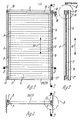
- the blind 1 shown in plan view in FIG. 1 has a frame which consists of a cross member 2 and two side members 3 and 4 and is open on one side, the cross member 2 having a U-profile open to the outside, the two side members 3 and 4, however, are made from a square hollow section. In the area of the corners denoted by 5, these are made, in particular, of spars 2 to 4 made of sheet metal and connected to one another by means of sheet metal screws (not shown in particular).
- FIGS. 2 and 4 there are in the inner walls 6 of these two side bars 3 and 4, each made from an angled sheet metal, a continuous longitudinal slot, designated 7, for holding and guiding the slats labeled 8, which are connected to one another like a chain by means of carrying cords designated by 9 in FIG. 1 and their tilted, the longitudinal direction of the side bars 3 in FIG. 1 and 4 assume approximately parallel closing position.
- a bearing pin designated 11 which, in the manner shown in FIGS. 4 and 5, protrude through the longitudinal slots 7 located in the inner walls 6 of the side rails 3 and 4.
- both the guide pieces 12 and the stop pieces 13 are expediently made of a wear-resistant plastic.
- two pull cords, designated 15, are provided, each accommodated in the side rails 3 and 4 and are laid around deflection rollers designated 16 and 17. While the deflecting rollers 17 facing away from the transverse spar 2 loosely circulate, the deflecting rollers 16 are arranged on a drive shaft 18 mounted in the transverse spar 2, which can be rotated by means of a drive rod 19 and a drive rod (not particularly shown). Depending on whether the drive shaft rotates in one or the other direction, the slats 8 are pulled apart in the direction of arrow 14 or contracted into the package shown in FIG. 5.
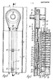
- the lamella 20 facing away from the cross bar 2 is connected to a support box 21 which forms the end of the frame opening facing away from the cross bar 2.
- This support box 21 has on both sides a bore designated 22 for receiving a freely rotatable journal 23.
- This journal 23 is cranked in the manner shown in FIG. 5 and ends in a crank designated 24.
- This crank 24 is connected via a loop 25 to the strand 26 of the pull cord 15 which is guided around the loose deflection roller 17.
- a helical tension spring 28 is further suspended by means of an eyelet 27, the other eyelet 29 of which engages again in the opposite loop 30 of the strand 31 of the same pull cord 15 which is wrapped around the driven deflection roller 16.
- each individual slat 8 and also of the carrying case 21 is determined by the arrangement of the slats 8 and the carrying case 21 on the carrying cords 9.
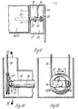
- FIG. 7 and 8 show a somewhat different embodiment of the blind 1, in which in addition to the two side bars 3 and 4 and the upper cross bar 2 there is also a lower cross bar 37 and these four bars form a self-contained frame 38.
- this frame 38 is seated on the upper edge 39 of a window sash designated by 40, which is pivotably mounted about a horizontal axis 41 in a window frame designated by 42.
- This window frame 42 can be arranged in the opening of a vertical wall, in the opening of an inclined roof or else in the opening of a flat roof.
- the blind frame 38 can be pivoted about a horizontal one Axle articulated on the window sash 40, by means of two bearing pins, designated 43, which engage in bores 44 located in the two side rails 3 of the blind frame 38.
- These journals 43 are each again fastened to a tab 45, which is to be inserted into an associated bearing block 47 screwed to the upper side 46 of the window sash 40.
- a bracket designated 49 is attached to the outside 48 of the bearing block 47, which together with the outside 48 of this bearing block 47 forms a narrow opening 50 into which the tab 45 in To be inserted in the direction of arrow 51.
- the free end 52 of this tab 45 must be bent around the bracket 49 in the manner shown in FIG. 11.
- This storage of the blind frame 38 according to the invention by means of these journals 43 and bearing blocks 47 is not only extremely simple, but also has the advantage that when the blind frame 38 is assembled after the two bearing blocks 47 have been attached to the window sash 40, the tabs 45 only have to be inserted into the associated pedestals 47 and the blind frame 38 is initially sufficiently held in this still unsecured state, to carry out the further assembly.
- the distance a between the upper edge 53 of the blind frame 38 and the pivot axis determined by the bearing pin 43 can also be minimized, which facilitates pivoting of the blind frame relative to the window sash 40.
- this second embodiment it is not the upper shaft 18, but the lower shaft 54 that is to be driven manually by means of a rotating crank, designated 55, which is mounted in the lower cross member 37 and projects laterally from the window sash 40. If the window sash 40 together with the blind frame 38 is pivoted outwards in the direction of the arrow 56, this crank 55 can be grasped by the person located on the inside of the window frame 42 and easily rotated.
- a rotating crank designated 55
- These two bow legs 60 are also assigned a sleeve 62 serving as a stop, which is clamped between the two bow legs 60 on the run 26 of the pull cord 15. If, for example, the lower shaft 54 is rotated by means of the rotating crank 55 and thus the strand 26 of the pull cord 15 is fed in the direction of the arrow 63, only the stop sleeve 62 is initially displaced by the distance determined by the distance between the two bow legs 60 to the sleeve length 1 shortened path b before this stop sleeve 62 strikes against the lower bracket leg 60 and takes the bracket 57 and thus the lower bearing pin 23 with it.
- the slats 8, 20 When the slats 8, 20 have been pulled out, the slats 8, 20 can be pivoted into their desired position by pivoting the lower drive shaft 54, the strand 26 of the pull cords 15 in question being displaced in the opposite direction of the arrow 63, the bracket 57 and thus the journal 23 with the lamellae 8, 20 cannot be taken along.
- FIGS. 14 and 15 show another possibility in which a transverse link 65 with a stop 66 is arranged on each of the two outer ends 64 of the lower drive shaft 54.
- This stop 66 is assigned a counter stop 67 located on the opposite, loosely rotating deflection roller 17, in the path of which the abovementioned stop 66 located on the transverse link 65 protrudes.
- the stop 66 takes the counterstop 67 with it, which causes the deflecting roller 17 to pivot and thus advance the strand 26 of the associated pull cord 15 and pull apart or push it together the result of slats 8.20.
- this lower drive shaft 54 is to be given a pivoting movement in the opposite direction of arrow 68, as a result of which the position of the individual lamellae 8, 20 can now be changed.
Landscapes
- Engineering & Computer Science (AREA)
- Structural Engineering (AREA)
- Architecture (AREA)
- Civil Engineering (AREA)
- Blinds (AREA)
Priority Applications (1)
| Application Number | Priority Date | Filing Date | Title |
|---|---|---|---|
| AT82107887T ATE16830T1 (de) | 1981-11-14 | 1982-08-27 | Jalousie. |
Applications Claiming Priority (4)
| Application Number | Priority Date | Filing Date | Title |
|---|---|---|---|
| DE3145358 | 1981-11-14 | ||
| DE3145358 | 1981-11-14 | ||
| DE19823221109 DE3221109A1 (de) | 1981-11-14 | 1982-06-04 | Jalousie |
| DE3221109 | 1982-06-04 |
Publications (2)
| Publication Number | Publication Date |
|---|---|
| EP0079434A1 true EP0079434A1 (fr) | 1983-05-25 |
| EP0079434B1 EP0079434B1 (fr) | 1985-12-04 |
Family
ID=25797337
Family Applications (1)
| Application Number | Title | Priority Date | Filing Date |
|---|---|---|---|
| EP82107887A Expired EP0079434B1 (fr) | 1981-11-14 | 1982-08-27 | Store à lamelles |
Country Status (2)
| Country | Link |
|---|---|
| EP (1) | EP0079434B1 (fr) |
| DE (2) | DE3221109A1 (fr) |
Cited By (1)
| Publication number | Priority date | Publication date | Assignee | Title |
|---|---|---|---|---|
| EP0340815A3 (en) * | 1984-08-07 | 1990-08-22 | Hunter Douglas Industries B.V. | Honeycomb blind constructions |
Families Citing this family (2)
| Publication number | Priority date | Publication date | Assignee | Title |
|---|---|---|---|---|
| DE3444238A1 (de) * | 1984-12-05 | 1986-06-05 | Ehage Jalousie-Fabrik Erich Hinnenberg GmbH & Co KG, 4006 Erkrath | Lamellenjalousie |
| AT501233B1 (de) * | 2004-12-22 | 2006-10-15 | Wo & Wo Gruen Gmbh | Kopfteil |
Citations (5)
| Publication number | Priority date | Publication date | Assignee | Title |
|---|---|---|---|---|
| US1907597A (en) * | 1932-04-21 | 1933-05-09 | Edward F Sibbert | Curtain operating device |
| DK103765C (da) * | 1962-06-28 | 1966-02-14 | Rasmussen & Co V K | Vindue. |
| DE2034321A1 (de) * | 1969-08-25 | 1971-03-04 | Gnesser"AG, Aadorf (Schweiz) | R äff store |
| DE2834268A1 (de) * | 1978-08-04 | 1980-02-28 | Hueppe Justin Fa | Lamellenjalousie |
| DE8133392U1 (de) * | 1981-11-14 | 1982-11-04 | Walter Paul KG, 7252 Weil der Stadt | "jalousie" |
-
1982
- 1982-06-04 DE DE19823221109 patent/DE3221109A1/de not_active Withdrawn
- 1982-08-27 DE DE8282107887T patent/DE3267814D1/de not_active Expired
- 1982-08-27 EP EP82107887A patent/EP0079434B1/fr not_active Expired
Patent Citations (5)
| Publication number | Priority date | Publication date | Assignee | Title |
|---|---|---|---|---|
| US1907597A (en) * | 1932-04-21 | 1933-05-09 | Edward F Sibbert | Curtain operating device |
| DK103765C (da) * | 1962-06-28 | 1966-02-14 | Rasmussen & Co V K | Vindue. |
| DE2034321A1 (de) * | 1969-08-25 | 1971-03-04 | Gnesser"AG, Aadorf (Schweiz) | R äff store |
| DE2834268A1 (de) * | 1978-08-04 | 1980-02-28 | Hueppe Justin Fa | Lamellenjalousie |
| DE8133392U1 (de) * | 1981-11-14 | 1982-11-04 | Walter Paul KG, 7252 Weil der Stadt | "jalousie" |
Cited By (1)
| Publication number | Priority date | Publication date | Assignee | Title |
|---|---|---|---|---|
| EP0340815A3 (en) * | 1984-08-07 | 1990-08-22 | Hunter Douglas Industries B.V. | Honeycomb blind constructions |
Also Published As
| Publication number | Publication date |
|---|---|
| DE3267814D1 (en) | 1986-01-16 |
| DE3221109A1 (de) | 1983-05-26 |
| EP0079434B1 (fr) | 1985-12-04 |
Similar Documents
| Publication | Publication Date | Title |
|---|---|---|
| DE69519764T2 (de) | Jalousierbarer Rolladen | |
| DE2703512C2 (de) | Rolltor für Hallen o.dgl. | |
| CH663063A5 (de) | Lamellenstoren. | |
| DE2729491A1 (de) | Streifenvorhang | |
| DE4101964A1 (de) | Rolladen | |
| DE3736153A1 (de) | Rolladen fuer dachfenster | |
| DE3320947C2 (de) | Bogenförmig verschiebbares Schiebetor | |
| DE2312661A1 (de) | Faltjalousie | |
| CH635164A5 (de) | Raffstore. | |
| DE2655235A1 (de) | Balgartig faltbare jalousie fuer fenster und tueren sowie vorrichtung zum oeffnen und schliessen derselben | |
| AT403829B (de) | Jalousierbarer rolladen | |
| DE2906913A1 (de) | Rolladen fuer dachwohnfenster | |
| DE2844891A1 (de) | Verschlusseinrichtung fuer fenster, tueren o.dgl. oeffnungen | |
| EP3521544B1 (fr) | Volet roulant pourvu d'arbre d'enroulement | |
| EP0716213A1 (fr) | Protection de levage pour volets ou portes roulants | |
| EP0079434A1 (fr) | Store à lamelles | |
| DE3625399A1 (de) | Rollo-vorhang fuer wohnwagenfenster | |
| WO2017109165A1 (fr) | Système de protection solaire | |
| DE814657C (de) | Kippjalousie | |
| EP1243744A1 (fr) | Jalousie avec course ascendante | |
| DE19600949A1 (de) | Rolladen für Fenster, Türen oder dergleichen | |
| DE3115926A1 (de) | Rolladen fuer dachfenster in schwenkfluegelbauweise | |
| EP1118746B1 (fr) | Stores à lamelles | |
| EP1031700B1 (fr) | Volet roulant pour fenêtres ou portes | |
| DE2746739C3 (de) | Lamellenjalousie für Fenster o.dgl. |
Legal Events
| Date | Code | Title | Description |
|---|---|---|---|
| PUAI | Public reference made under article 153(3) epc to a published international application that has entered the european phase |
Free format text: ORIGINAL CODE: 0009012 |
|
| AK | Designated contracting states |
Designated state(s): AT BE CH DE FR LI NL SE |
|
| 17P | Request for examination filed |
Effective date: 19830621 |
|
| GRAA | (expected) grant |
Free format text: ORIGINAL CODE: 0009210 |
|
| AK | Designated contracting states |
Designated state(s): AT BE CH DE FR LI NL SE |
|
| REF | Corresponds to: |
Ref document number: 16830 Country of ref document: AT Date of ref document: 19851215 Kind code of ref document: T |
|
| REF | Corresponds to: |
Ref document number: 3267814 Country of ref document: DE Date of ref document: 19860116 |
|
| ET | Fr: translation filed | ||
| PG25 | Lapsed in a contracting state [announced via postgrant information from national office to epo] |
Ref country code: SE Effective date: 19860131 |
|
| PGFP | Annual fee paid to national office [announced via postgrant information from national office to epo] |
Ref country code: AT Payment date: 19860826 Year of fee payment: 5 |
|
| PGFP | Annual fee paid to national office [announced via postgrant information from national office to epo] |
Ref country code: NL Payment date: 19860831 Year of fee payment: 5 |
|
| PLBE | No opposition filed within time limit |
Free format text: ORIGINAL CODE: 0009261 |
|
| STAA | Information on the status of an ep patent application or granted ep patent |
Free format text: STATUS: NO OPPOSITION FILED WITHIN TIME LIMIT |
|
| 26N | No opposition filed | ||
| BERE | Be: lapsed |
Owner name: WALTER PAUL K.G. Effective date: 19860831 |
|
| BERE | Be: lapsed |
Owner name: WALTER PAUL K.G. Effective date: 19870831 |
|
| PG25 | Lapsed in a contracting state [announced via postgrant information from national office to epo] |
Ref country code: NL Effective date: 19880301 |
|
| NLV4 | Nl: lapsed or anulled due to non-payment of the annual fee | ||
| PG25 | Lapsed in a contracting state [announced via postgrant information from national office to epo] |
Ref country code: FR Free format text: LAPSE BECAUSE OF NON-PAYMENT OF DUE FEES Effective date: 19880429 |
|
| REG | Reference to a national code |
Ref country code: FR Ref legal event code: ST |
|
| PG25 | Lapsed in a contracting state [announced via postgrant information from national office to epo] |
Ref country code: AT Effective date: 19880827 |
|
| PG25 | Lapsed in a contracting state [announced via postgrant information from national office to epo] |
Ref country code: LI Effective date: 19880831 Ref country code: CH Effective date: 19880831 |
|
| REG | Reference to a national code |
Ref country code: CH Ref legal event code: PL |
|
| PG25 | Lapsed in a contracting state [announced via postgrant information from national office to epo] |
Ref country code: BE Effective date: 19890831 |
|
| PGFP | Annual fee paid to national office [announced via postgrant information from national office to epo] |
Ref country code: DE Payment date: 19911231 Year of fee payment: 10 |
|
| PG25 | Lapsed in a contracting state [announced via postgrant information from national office to epo] |
Ref country code: DE Effective date: 19930501 |