EP0079542A2 - Verfahren zur zweidimensionalen digitalen linearen Interpolation - Google Patents
Verfahren zur zweidimensionalen digitalen linearen Interpolation Download PDFInfo
- Publication number
- EP0079542A2 EP0079542A2 EP82110200A EP82110200A EP0079542A2 EP 0079542 A2 EP0079542 A2 EP 0079542A2 EP 82110200 A EP82110200 A EP 82110200A EP 82110200 A EP82110200 A EP 82110200A EP 0079542 A2 EP0079542 A2 EP 0079542A2
- Authority
- EP
- European Patent Office
- Prior art keywords
- data
- input
- interpolated
- line
- output
- Prior art date
- Legal status (The legal status is an assumption and is not a legal conclusion. Google has not performed a legal analysis and makes no representation as to the accuracy of the status listed.)
- Withdrawn
Links
Images





Classifications
-
- G—PHYSICS
- G06—COMPUTING OR CALCULATING; COUNTING
- G06T—IMAGE DATA PROCESSING OR GENERATION, IN GENERAL
- G06T3/00—Geometric image transformations in the plane of the image
- G06T3/40—Scaling of whole images or parts thereof, e.g. expanding or contracting
- G06T3/4007—Scaling of whole images or parts thereof, e.g. expanding or contracting based on interpolation, e.g. bilinear interpolation
-
- G—PHYSICS
- G06—COMPUTING OR CALCULATING; COUNTING
- G06F—ELECTRIC DIGITAL DATA PROCESSING
- G06F17/00—Digital computing or data processing equipment or methods, specially adapted for specific functions
- G06F17/10—Complex mathematical operations
- G06F17/17—Function evaluation by approximation methods, e.g. inter- or extrapolation, smoothing, least mean square method
- G06F17/175—Function evaluation by approximation methods, e.g. inter- or extrapolation, smoothing, least mean square method of multidimensional data
-
- H—ELECTRICITY
- H04—ELECTRIC COMMUNICATION TECHNIQUE
- H04N—PICTORIAL COMMUNICATION, e.g. TELEVISION
- H04N1/00—Scanning, transmission or reproduction of documents or the like, e.g. facsimile transmission; Details thereof
- H04N1/40—Picture signal circuits
- H04N1/40068—Modification of image resolution, i.e. determining the values of picture elements at new relative positions
Definitions
- the present invention relates to an interpolation system for video display devices, and, more particularly, to an interpolation system capable of using a one-dimensional interpolator to perform both the X and Y interpolation.
- Video display systems have been developed which employ digital technology for transmission and storage of display data.
- a display can be stored digitally and retrieved to generate a video image by redintegration of the image pixel to pixel.
- the need for two-dimensional interpolation arises when providing a zoom capability for the display of digitized images required either to reconstruct an image only part of which was actually stored, or to produce an enlarged view of a smaller image.
- a typical method for providing this capability is to add interpolated pixels (picture cells) between the original data pixels. The number of added pixels determines the amount of zoom provided.
- Table 1 An example of a four to one zoom is illustrated in Table 1. In the original data lines 0 and 1 are stored as a series of pixels at points 0, 1, etc., as shown in part (a) of Table 1.
- two-dimensional interpolation lines 0 and 1 are separated by lines whose position is designated 0.1, 0.2 and 0.3 and the original pixels in each line are separated by pixels whose position is designated 0.1, 0.2 and 0.3, as shown in part (b) of Table 1.
- This pattern is repeated for the full extent of the video image, thereby linearly expanding the image in two dimensions.
- an intensity data for each pixel is stored. The intensity determines the shade ranging from white to black that will be displayed by the video display.
- the interpolation between pixels provides a value of intensity for the interpolated pixels.
- a typical method for determining the intensity values of the interpolated pixels based upon the intensity values of the original image pixels is called a bilinear interpolation.
- the formula for obtaining the interpolated pixels is as follows: where I is the intensity of a pixel designated by its subscript, and a and ß represent the x (horizontal and y (vertical) coordinates, respectively, of the image array expressed as fractional distances between the stored pixel values (0 ⁇ a ⁇ 1 and 0 ⁇ S ⁇ 1).
- the terms enclosed in the first set of square brackets represent a linear interpolation in the direction of the two pixels in the top line of the four pixel image represented in Fig. la.
- the terms of the second set of square brackets represent a linear interpolation in the x direction of the two pixels in the bottom line.
- the x direction interpolation creates new pixels between the original pixels as a single line.
- the weighted combination of the quantities in the two square brackets represents an interpolation of the y dimension which creates new interpolation in the x dimension, thus resulting in the four to one bilinear interpolated image having the relative weights of the intensifies along the a and S dimensions shown in Fig. lb.
- the value of a in the x dimension varies in uniform increments from 0 through 1, in that a linear interpolation is produced by the formula above.
- S varies uniformly in the y dimension to produce the linear interpolation in the vertical direction.
- the bilinear interpolator function has typically been accomplished by employing a computer with an image stored in its memory to compute an enlarged image which must also be stored in the computer memory.
- This method of interpolation is slow and results in delays of several seconds between the initiation of a zoom request and display of the image.
- a requirement of many display systems is the need to rapidly switch between many enlarged images, and for these applications a large lead time is required to permit the computation of the many enlarged images required.
- each image is fed into a computer which generates the interpolations necessary to enlarge the image, and then stores the enlarged image into computer memory.
- Each separate image requires a separate memory capable of storing data for each pixel of the image, typically 64,000 cells, and the circuitry necessary to quickly switch between a plurality of stored image memories in order to produce a simulated real time image.
- An alternative approach to realizing a real time interpclator would be tc use three linear interpolators.
- One interpolator would provide interpolation in the x direction for a designated line.
- a second interpolator would compute interpolated pixels in the x direction for a succeeding line to provide sets of pixel data for a y direction interpolation performed by the third interpolator.
- This approach would require many more parts for the additional interpolators and, since two image lines must be read simultaneously from the image memory in order to perform the y direction interpolation, a more complicated memory control circuit with additional parts would be required.
- An object of the present invention is to provide a real time image interpolation system capable of operating at high speed.
- a more particular object of the present invention is to provide a digital linear interpolation system which employs a single one-dimensional interpolator to perform both x and y interpolation for real time video display.
- the present invention includes a video data input providing video data image data to an input register and a data multiplexer.
- a horizontal interpolation is performed for a first line and the output image data stored in a line buffer.
- a horizontal interpolation is performed for the next successive line and the output image data stored in another line buffer.
- the interpolator then performs the vertical interpolation which is outputted to the display without storage.
- Output of the interpolated data is controlled so that the interpolated data for a line stored in one line buffer is provided to an output multiplexer.
- interpolation of the next line and storage in a second line buffer is carried out. Following output from the first line buffer,interpolated data lines are computed and output in real time.
- Output from the second line buffer then takes place while a third line is interpolated and stored in the first line buffer, followed by computation and output of interpolated data lines. This sequence is repeated throughout the remainder of that image.
- the present system can be combined with a variety of image mapping schemes to enhance the image displayed to the user.
- the four interpolator states shown in Table 2 provide all the combinations of a system having two inputs, a and b, needed for a four to one interpolation.
- the four states correspond to the four different combinations of data required to be outputted from the interpolator; namely: b, 3/4 a + 1/4 b, 1/2 a + 1/2b, 1/4 a + 3/4b, to produce a linear interpolation of an image.
- These four sums, one for each state, are the only computations needed for a four-to-one interpolation where a and b represent the image data for stored image pixels.
- Other interpolation expansions can be performed by providing the necessary number of interpolator states. Data can be fed through the interpolator with no change if only state one is used to produce a display image corresponding directly to the stored image.
- FIG. 2 A block diagram of a one-dimensional four-to-one interpolator 10 of the present invention is shown in Fig. 2.
- the one-dimensional interpolator 10 computes the sum of the two multiplexer outputs 12 and 16 plus the b input 17 for each state shown in Table 2.
- Input lineal provides the "a" input data to multiplexers 14 and 18 and input line 13 provides the "b" input data to multiplexers 14, 18 and summer 20.
- Multiplexer 14 provides an output 12 of a or b to to summer 24.
- Multiplexer 18 provides an output 16 of a or b to summer 20.
- Summer 20 provides an output 22 scaled to 1/4 a + 1/4 b or 1/2b.
- the output 26 of summer 24 is scaled to be b; 3/4 + l/4b; 1/2 a + 1/2 b; or 1/4 a + 3/4 b. These quantities are obtained by shifting a or b, respectively, by one bit in summer 20 and one bit in summer 24. No actual shifting occurs at the multiplexer output 12 but instead the data is considered scaled to 1/2 (a or b) which is accounted for by a hardwired upshift of one bit in summer 24.
- the output 16 of the lower multiplexer 18 is scaled by 1/2 or a shift of two bits. One bit of the scaling is accounted for by a hardwired upshift of one bit at the first summer output 20.
- the output 22 of this summer 20 then goes to the second summer 24 which accounts for the second bit of shift.
- the scaling is accounted for by hardwired upshifting of the summer outputs 22, 26 by one bit each, as shown at 28 and 30 in Fig. 3.
- the lsb (least significant bit) 32 of the summer output 22 is ignored.
- the next least significant bit 36 of the summer output 22 is made the lsb of the input to summer 24.
- the lsb 34 of the output of summer 24 is ignored. This results in another bit of scaling of the output. Therefore, the inputs 16 and 17 result in an output from summer 24 scaled by 1/4 to be 1/4 a + 1/4 b or 1/2b. Since the input 12 to summer 24 is scaled once, the lsb 15 of input 12 is ignored, and the output 26 includes 1/2 a or 1/2 b.
- the one-dimensional interpolator is used as a building block to create a two-dimensional interpolator.
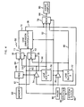
- a block diagram of the logic circuits comprising a two-dimensional interpolator 50 is shown in Fig. 4.
- the one-dimensional interpolator inputs 11 and 13 are obtained from a pair of multiplexers 56, 58, which are switched in unison so that both of the top inputs 60, 62 or both of the bottom inputs 64, 66 are selected together.
- the top inputs 60, 62 are used when inputting a new line of data from a memory unit 52.
- Input register 68 stores the second of two data points being interpolated and ouputs it to the interpolator 10 in conjunction with the data input 62 to provide the two data points necessary to the interpolation.
- the control for the two-dimensional interpolator illustrated in Fig. 4 is obtained from counter 92, which provides the addresses for PROM 94 (Programmable Read Only Memory).
- PROM 94 Program Read Only Memory
- the output of PROM 94 supplies the proper signals to strobe register 68, switch multiplexers 56, 58 and 78, enable gates 74 and 76, control the read or write modes of line buffers 70 and 72 and sequence the one-dimensional interpolator 10 through its states by controlling the outputs of multiplexers 14 and 18.
- the PROM is programmed to provide the control signals in the proper sequence to achieve the bilinear interpolation action.
- the counter is driven from the system clock 90 to insure synchronism with the other functions in the total video processing unit.
- the operation of the interpolator proceeds as follows when the. successive data points P 1 and P 2 are being interpolated.
- the first point P 1 is clocked through the interpolator with no change and input at 61 to input register 68. It enters the one-dimensional interpolator 10 at the input 13 and is processed with the one-dimensional interpolator set in state 1 of Table 2.
- the second point P 2 is then put on the data input lines 61, 62.
- the first point P 1 is now input from input register 68 to a multiplexer 56 and via input 52 to the one-dimensional interpolator 10, and the second point P 2 is input through multiplexer 58 to interpolator 10 via input 13.
- the one-diemsnional interpolator 10 is then stepped through states 2, 3 and 4 of Table 2.
- the output is clocked once for each state, producing three interpolated points between the first and second data pulses.
- the cycle then starts again with the second point being passed unchanged through the one-dimensional interpolator while in state 1.
- the data sequence is shown in Table 3. Clock pulses starting at pulse n and being incremented at each clock interval are employed to time the sequence of steps for the interpolator.
- the b input is the 0 point pixel data from memory to input 13 of interpolator 16. No interpolation occurs, since only one data point is available to the interpolator.
- the data for the 0 point could be output at any of the time periods n through n + 3. However, in order to provide a continuous.data flow, output of the unaltered 0 point data is delayed until time n + 3. At time n + 4, the 0 point data becomes available as the input from the input register and the 1 point data becomes available at input b.
- Interpolation proceeds immediately to produce the interpolated data for the points, 0.1, 0.2 and 0.3 with the interpolator stepping through states 2, 3 and 4 as shown on the line labelled "interpolator states" of Table 3.
- the input from the interpolator is a series of consecutive values for the respective data points as shown in the lines labelled r of-Table 2.
- the data point numbers n.l, etc. are the first interpolated data points between data points n and n + 1.
- Data point numbers n.2 and n.3 are the second and third interpolated points, respectively.
- the one-dimensionally interpolated data stored in the two line buffers 70, 72 are then-used to calculate the interpolated lines, which are the result of interpolation in the Y dimension between corresponding points of the two stored lines.
- Only states 2, 3 and 4 of the one-dimensional interpolator (Table 2) are used for the Y direction interpolation or every fourth line in the sequence is obtained from one of the line buffers 70 or 72 to ensure outputting the lines in a continuous sequence via output multiplexer 78 to video display 80.
- the state of the one-dimensional interpolation is held constant throughout the generation of an entire interpolated line and changes only between lines.
- Table 4 The data sequence for 4-tO-l interpolation in the y dimension is shown in Table 4.
- Line n.l in the column labelled "Line Number Outputted” is the first interpolated line between lines n and n+1.
- Line n.2 and n.3 are the second and third interpolated lines, respectively.
- ALL indicates that the interpolator cycles through all four states while interpolating along a line to produce the x dimension interpolation.
- BLACK indicates the output is held at the intensity value equivalent to black on the display. The black output line will produce a border along the edge of the display image, but this is a small effect which neither interferes with the number of the image nor causes any data handling complexity in the interpolation system.
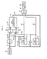
- FIG. 5 depicts the data paths used when interpolating and storing the first line (line 0) of an image.
- Input data is supplied from register 68 via input 60 to multiplexer 56 and via input 11 and from memory 52 via input 62 multiplexer 58 and input 13 to the one-dimensional interpolator 10 where interpolated data is calculated, which is written into line buffer 70 via gate 74 and input 75 as line a.
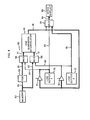
- Fig. 6 shows the data flow as line 1 is inputted, interpolated in the X dimension in the same way as line 0 was handled, and the interpolated data stored in the buffer 72 via gate 76 and input 77. Simultaneously with interpolation of line 1, line 0 is read out of buffer 70 via input line 82 to output multiplexer 78 and line 84 to display 80 as shown in Fig. 6.
- Fig. 8 is similar to Fig. 6 except that the line buffer being written into and read out of are interchanged. As the data from successive interpolated lines is completed, storage of the data must be alternated between the two line buffers. The direction of the interpolation in the Y dimension will go first from line buffer 70 to line buffer 72.
- the image display pattern is shown in Fig. 9, along with the image display pattern of a direct data display.
- Fig. 9a shows the arrangement of pixels in a display system in which each pixel is stored in a memory location and separately read out when a display of the data is required.
- Fig. 9b shows the data pattern which results from a four-to-one interpolation according to the present invention.
- the top three rows and leftmost three pixels in each row of Fig. 9b are black, represented by the "b's", since no interpolated data can be produced until a second data input is received, and output of line 0 is delayed until line n+3, so that no gaps in output occur.
- the black border produced by this waiting causes no significant loss of image and enables the system to be implemented with a minimum of hardware.
- the interpolator When providing real time images the interpolator must perform the complete interpolation of the entire image once during each scan time.
- the present invention allows this to be done with minimum hardware. Since only the stored data has to be inputted to the system, the amount of memory required is reduced, In the example described above the memory required is reduced from a 256 x 256 memory to a 64 x 64 memory, representing a reduction to one-sixteenth of the memory required for direct storage. Also for real time display, the present invention requires inputting of only one-sixteenth the data and can provide full scale display of successive images at the scan rate of the CRT display, so that the limit on real time display is the CRT scan rate rather than the data input equipment speed.
- a single one-dimensional interpolator to achieve two-dimensional interpolaticn in real time results in a substantial reduction in hardware, and simultaneously reduces the time delay between data acquisition by an imaging device, such as a nuclear scanning imager and image display to such extent that successive images are displayed as they are produced.
- an imaging device such as a nuclear scanning imager
- the present invention allows immediate image evaluation, so that need for further images may be determined immediately, and, if needed, accomplished without requiring the patient to return at a separate time.
- Alsq real time imaging allows evaluation of moving parts, such as a beating heart, thereby further facilitating accurate and immediate diagnosis of condition of the patient.
- the data discussed above is described as intensity values.
- the system employs 12 bit data to provide 12 bit variation in intensity data.
- the output data can be used to produce a color display by mapping the intensity data onto a color spectrum. Many variations of the data mapping may be employed to produce a particular desired display, e.g. false color can be used for contrast enhancement.
- the output from the two-dimensional interpolator of the present invention thus offers great flexibility in display system design, allowing the system designer to determine the optimum mapping of the data output by the interpolator system.
- Data in other than 12 bit format may be employed depending on the use to be made of the output data. Therefore, the present invention offers the speed necessary for real time image display with a minimum hardware requirement and at the same time offers great system flexibility.
Landscapes
- Engineering & Computer Science (AREA)
- Physics & Mathematics (AREA)
- General Physics & Mathematics (AREA)
- Theoretical Computer Science (AREA)
- Mathematical Physics (AREA)
- Computational Mathematics (AREA)
- Mathematical Analysis (AREA)
- Mathematical Optimization (AREA)
- Pure & Applied Mathematics (AREA)
- Data Mining & Analysis (AREA)
- Algebra (AREA)
- Databases & Information Systems (AREA)
- Software Systems (AREA)
- General Engineering & Computer Science (AREA)
- Multimedia (AREA)
- Signal Processing (AREA)
- Image Processing (AREA)
- Digital Computer Display Output (AREA)
Applications Claiming Priority (2)
| Application Number | Priority Date | Filing Date | Title |
|---|---|---|---|
| US06/321,890 US4402012A (en) | 1981-11-16 | 1981-11-16 | Two-dimensional digital linear interpolation system |
| US321890 | 1981-11-16 |
Publications (2)
| Publication Number | Publication Date |
|---|---|
| EP0079542A2 true EP0079542A2 (de) | 1983-05-25 |
| EP0079542A3 EP0079542A3 (de) | 1986-06-04 |
Family
ID=23252481
Family Applications (1)
| Application Number | Title | Priority Date | Filing Date |
|---|---|---|---|
| EP82110200A Withdrawn EP0079542A3 (de) | 1981-11-16 | 1982-11-05 | Verfahren zur zweidimensionalen digitalen linearen Interpolation |
Country Status (4)
| Country | Link |
|---|---|
| US (1) | US4402012A (de) |
| EP (1) | EP0079542A3 (de) |
| JP (1) | JPS58105374A (de) |
| IL (1) | IL66863A (de) |
Cited By (9)
| Publication number | Priority date | Publication date | Assignee | Title |
|---|---|---|---|---|
| EP0241424A1 (de) * | 1986-04-08 | 1987-10-14 | Battelle Memorial Institute | Verfahren zur Bestimmung des Durchflusses eines Fluids |
| GB2224410A (en) * | 1988-10-26 | 1990-05-02 | Marconi Gec Ltd | Video image magnification system |
| EP0356224A3 (de) * | 1988-08-25 | 1991-04-17 | Canon Kabushiki Kaisha | Datenverarbeitungsgerät |
| WO1992001260A1 (en) * | 1990-07-09 | 1992-01-23 | Eastman Kodak Company | Selectable power of two coefficient signal combining circuits |
| EP0617554A1 (de) * | 1993-03-24 | 1994-09-28 | miro Computer Products AG | Verfahren zur vergrösserten Wiedergabe von Videobildern |
| DE4442426A1 (de) * | 1993-11-29 | 1995-06-01 | Kokusai Electric Co Ltd | Verfahren und Vorrichtung zum Übertragen von Bilddaten |
| GB2293938A (en) * | 1994-10-04 | 1996-04-10 | Winbond Electronics Corp | Two dimensional spatial interpolator for digital video format converter |
| GB2371459A (en) * | 2001-01-19 | 2002-07-24 | Pixelfusion Ltd | Image scaling |
| CN1110017C (zh) * | 1995-07-31 | 2003-05-28 | 华邦电子股份有限公司 | 可均匀伸缩数字图象尺寸的方法及其装置 |
Families Citing this family (27)
| Publication number | Priority date | Publication date | Assignee | Title |
|---|---|---|---|---|
| JPS57208765A (en) * | 1981-06-18 | 1982-12-21 | Dainippon Screen Mfg Co Ltd | Signal interpolating method for memory device |
| GB8306339D0 (en) * | 1982-03-19 | 1983-04-13 | Quantel Ltd | Video processing systems |
| JPS59214710A (ja) * | 1983-05-23 | 1984-12-04 | Hitachi Ltd | ナビゲ−シヨン装置 |
| GB2160051A (en) * | 1984-04-26 | 1985-12-11 | Philips Electronic Associated | Video signal processing arrangement |
| US4707742A (en) * | 1984-04-26 | 1987-11-17 | U.S. Philips Corporation | Video signal processing arrangement |
| JPS6231482A (ja) * | 1985-08-02 | 1987-02-10 | Canon Inc | 画像処理装置 |
| JP2604711B2 (ja) * | 1985-09-14 | 1997-04-30 | ソニー株式会社 | 画像変換装置 |
| IL80208A0 (en) * | 1985-11-26 | 1987-01-30 | Honeywell Inc | Method and apparatus for increasing vertical resolution on an optical scanner output |
| NL8602493A (nl) * | 1986-10-03 | 1988-05-02 | Philips Nv | Lijnentalhalveerschakeling voor een bemonsterd geinterlineerd televisiesignaal. |
| EP0280932B1 (de) * | 1987-03-04 | 1992-11-19 | Hitachi, Ltd. | Gerät zur Wiedergabe von Videosignalen geringer Auflösung auf Videomonitoren hoher Auflösung |
| US4764805A (en) * | 1987-06-02 | 1988-08-16 | Eastman Kodak Company | Image transmission system with line averaging preview mode using two-pass block-edge interpolation |
| JPS6453274A (en) * | 1987-08-25 | 1989-03-01 | Hitachi Ltd | Interpolation device having line segment processing part running parallel with coordinate axis |
| JP2637438B2 (ja) * | 1987-10-27 | 1997-08-06 | キヤノン株式会社 | 画像処理装置 |
| US4885688A (en) * | 1987-11-25 | 1989-12-05 | General Electric Company | Minimization of directed points generated in three-dimensional dividing cubes method |
| US4908780A (en) * | 1988-10-14 | 1990-03-13 | Sun Microsystems, Inc. | Anti-aliasing raster operations utilizing sub-pixel crossing information to control pixel shading |
| US5170475A (en) * | 1989-03-06 | 1992-12-08 | Motorola, Inc. | Data processor having instructions for interpolating between memory-resident data values respectively |
| US5175701A (en) * | 1989-07-25 | 1992-12-29 | Eastman Kodak Company | System for performing linear interpolation |
| US5025315A (en) * | 1990-09-06 | 1991-06-18 | Chips And Technologies, Inc. | Method and apparatus for scaling interlaced images |
| DE69222102T2 (de) * | 1991-08-02 | 1998-03-26 | Grass Valley Group | Bedienerschnittstelle für Videoschnittsystem zur Anzeige und interaktive Steuerung von Videomaterial |
| JP2732772B2 (ja) * | 1992-05-19 | 1998-03-30 | 松下電器産業株式会社 | デジタル信号処理回路 |
| JP2618156B2 (ja) * | 1992-06-08 | 1997-06-11 | インターナショナル・ビジネス・マシーンズ・コーポレイション | ドット・マトリックス表示パネルの駆動方法、ドット・マトリックス表示パネル用駆動回路、ドット・マトリックス表示装置、及び、ドット・マトリックス表示装置を備えた情報処理システム |
| US5646696A (en) * | 1992-12-23 | 1997-07-08 | Intel Corporation | Continuously changing image scaling performed by incremented pixel interpolation |
| US5469222A (en) * | 1992-12-23 | 1995-11-21 | Intel Corporation | Non-linear pixel interpolator function for video and graphic processing |
| US5677967A (en) * | 1993-03-10 | 1997-10-14 | R. R. Donnelley & Sons Company | Method of and apparatus for converting between a color appearance space and a colorant space |
| US5801678A (en) * | 1996-04-26 | 1998-09-01 | Industrial Technology Research Institute | Fast bi-linear interpolation pipeline |
| WO2010126783A2 (en) * | 2009-04-30 | 2010-11-04 | Roman Gitlin | Method and apparatus for streamlined implementation of interpolation in multiple dimensions |
| US10817493B2 (en) | 2017-07-07 | 2020-10-27 | Raytheon Company | Data interpolation |
Family Cites Families (4)
| Publication number | Priority date | Publication date | Assignee | Title |
|---|---|---|---|---|
| US4068266A (en) * | 1976-06-03 | 1978-01-10 | Xerox Corporation | Statistical resolution conversion technique |
| US4303947A (en) * | 1978-06-21 | 1981-12-01 | Xerox Corporation | Image interpolation system |
| US4193092A (en) * | 1978-06-21 | 1980-03-11 | Xerox Corporation | Image interpolation system |
| GB2046053B (en) * | 1979-03-22 | 1983-06-15 | Micro Consultants Ltd | Digital video processor |
-
1981
- 1981-11-16 US US06/321,890 patent/US4402012A/en not_active Expired - Fee Related
-
1982
- 1982-09-24 IL IL66863A patent/IL66863A/xx unknown
- 1982-11-05 EP EP82110200A patent/EP0079542A3/de not_active Withdrawn
- 1982-11-16 JP JP57199840A patent/JPS58105374A/ja active Pending
Cited By (15)
| Publication number | Priority date | Publication date | Assignee | Title |
|---|---|---|---|---|
| CH667919A5 (fr) * | 1986-04-08 | 1988-11-15 | Battelle Memorial Institute | Procede pour determiner le debit d'un fluide. |
| EP0241424A1 (de) * | 1986-04-08 | 1987-10-14 | Battelle Memorial Institute | Verfahren zur Bestimmung des Durchflusses eines Fluids |
| US5754188A (en) * | 1988-08-25 | 1998-05-19 | Canon Kabushiki Kaisha | Data processing apparatus |
| EP0356224A3 (de) * | 1988-08-25 | 1991-04-17 | Canon Kabushiki Kaisha | Datenverarbeitungsgerät |
| GB2224410A (en) * | 1988-10-26 | 1990-05-02 | Marconi Gec Ltd | Video image magnification system |
| WO1992001260A1 (en) * | 1990-07-09 | 1992-01-23 | Eastman Kodak Company | Selectable power of two coefficient signal combining circuits |
| EP0617554A1 (de) * | 1993-03-24 | 1994-09-28 | miro Computer Products AG | Verfahren zur vergrösserten Wiedergabe von Videobildern |
| DE4442426A1 (de) * | 1993-11-29 | 1995-06-01 | Kokusai Electric Co Ltd | Verfahren und Vorrichtung zum Übertragen von Bilddaten |
| DE4442426C2 (de) * | 1993-11-29 | 2001-02-15 | Kokusai Electric Co Ltd | Verfahren und Vorrichtung zum Übertragen von Bilddaten |
| GB2293938A (en) * | 1994-10-04 | 1996-04-10 | Winbond Electronics Corp | Two dimensional spatial interpolator for digital video format converter |
| GB2293938B (en) * | 1994-10-04 | 1999-01-20 | Winbond Electronics Corp | Apparatus for digital video format conversion |
| CN1110017C (zh) * | 1995-07-31 | 2003-05-28 | 华邦电子股份有限公司 | 可均匀伸缩数字图象尺寸的方法及其装置 |
| GB2371459A (en) * | 2001-01-19 | 2002-07-24 | Pixelfusion Ltd | Image scaling |
| US6825857B2 (en) | 2001-01-19 | 2004-11-30 | Clearspeed Technology Limited | Image scaling |
| GB2371459B (en) * | 2001-01-19 | 2005-05-04 | Pixelfusion Ltd | Image scaling |
Also Published As
| Publication number | Publication date |
|---|---|
| JPS58105374A (ja) | 1983-06-23 |
| IL66863A (en) | 1985-06-30 |
| EP0079542A3 (de) | 1986-06-04 |
| US4402012A (en) | 1983-08-30 |
Similar Documents
| Publication | Publication Date | Title |
|---|---|---|
| US4402012A (en) | Two-dimensional digital linear interpolation system | |
| US5793379A (en) | Method and apparatus for scaling images having a plurality of scan lines of pixel data | |
| US4631750A (en) | Method and system for spacially transforming images | |
| US4858020A (en) | Image sensing device | |
| US4472732A (en) | System for spatially transforming images | |
| US4661987A (en) | Video processor | |
| US5125043A (en) | Image processing with real time zoom logic | |
| EP0201148A2 (de) | Vordezimierungsfilter für Bildveränderungssystem | |
| US4719588A (en) | Matrix multiplication circuit for graphic display | |
| EP0076259A1 (de) | Steuerung für ein gerät zur räumlichen transformation von bildern. | |
| JPH0750810A (ja) | デジタルビデオ特殊効果装置 | |
| US5307167A (en) | Digital zooming system utilizing image buffers and employing an approximated bilinear interpolation method | |
| US4819190A (en) | Video line processor | |
| US5060172A (en) | Method and apparatus for displaying smooth-shaded objects | |
| US5418901A (en) | Shading method and shading apparatus for computer graphics | |
| JPH0812690B2 (ja) | 画像縮尺装置 | |
| EP0511606B1 (de) | Parallelinterpolator für Hochgeschwindigkeits-Digitalbildvergrösserung | |
| US20060170954A1 (en) | Method and system for generating synchronous multidimensional data streams from a one -dimensional data stream | |
| GB2157126A (en) | Controller for system for spatially transforming images | |
| JP2510019B2 (ja) | 画像表示方法および装置 | |
| EP0491036A1 (de) | Signalkombinationsschaltung mit auswählbarem zweierpotenzzugriff | |
| JPH02135880A (ja) | 撮像装置 | |
| JPH06266831A (ja) | 画像処理装置 | |
| JPS63245084A (ja) | インタレ−ス画像デ−タ変換方式 | |
| WO1998043422A1 (en) | Bilinear decimator with error compensation |
Legal Events
| Date | Code | Title | Description |
|---|---|---|---|
| PUAI | Public reference made under article 153(3) epc to a published international application that has entered the european phase |
Free format text: ORIGINAL CODE: 0009012 |
|
| AK | Designated contracting states |
Designated state(s): DE FR GB NL |
|
| PUAL | Search report despatched |
Free format text: ORIGINAL CODE: 0009013 |
|
| AK | Designated contracting states |
Kind code of ref document: A3 Designated state(s): DE FR GB NL |
|
| STAA | Information on the status of an ep patent application or granted ep patent |
Free format text: STATUS: THE APPLICATION HAS BEEN WITHDRAWN |
|
| 18W | Application withdrawn |
Withdrawal date: 19861127 |
|
| RIN1 | Information on inventor provided before grant (corrected) |
Inventor name: KNIGHT, WESLEY WILLARD |