EP0079656A1 - Extrudeuse pour matière plastique - Google Patents
Extrudeuse pour matière plastique Download PDFInfo
- Publication number
- EP0079656A1 EP0079656A1 EP82201429A EP82201429A EP0079656A1 EP 0079656 A1 EP0079656 A1 EP 0079656A1 EP 82201429 A EP82201429 A EP 82201429A EP 82201429 A EP82201429 A EP 82201429A EP 0079656 A1 EP0079656 A1 EP 0079656A1
- Authority
- EP
- European Patent Office
- Prior art keywords
- screw
- cylinder
- extruder according
- thread
- feed chamber
- Prior art date
- Legal status (The legal status is an assumption and is not a legal conclusion. Google has not performed a legal analysis and makes no representation as to the accuracy of the status listed.)
- Granted
Links
Images
Classifications
-
- B—PERFORMING OPERATIONS; TRANSPORTING
- B29—WORKING OF PLASTICS; WORKING OF SUBSTANCES IN A PLASTIC STATE IN GENERAL
- B29C—SHAPING OR JOINING OF PLASTICS; SHAPING OF MATERIAL IN A PLASTIC STATE, NOT OTHERWISE PROVIDED FOR; AFTER-TREATMENT OF THE SHAPED PRODUCTS, e.g. REPAIRING
- B29C48/00—Extrusion moulding, i.e. expressing the moulding material through a die or nozzle which imparts the desired form; Apparatus therefor
- B29C48/25—Component parts, details or accessories; Auxiliary operations
- B29C48/36—Means for plasticising or homogenising the moulding material or forcing it through the nozzle or die
- B29C48/50—Details of extruders
- B29C48/501—Extruder feed section
-
- B—PERFORMING OPERATIONS; TRANSPORTING
- B29—WORKING OF PLASTICS; WORKING OF SUBSTANCES IN A PLASTIC STATE IN GENERAL
- B29C—SHAPING OR JOINING OF PLASTICS; SHAPING OF MATERIAL IN A PLASTIC STATE, NOT OTHERWISE PROVIDED FOR; AFTER-TREATMENT OF THE SHAPED PRODUCTS, e.g. REPAIRING
- B29C48/00—Extrusion moulding, i.e. expressing the moulding material through a die or nozzle which imparts the desired form; Apparatus therefor
- B29C48/25—Component parts, details or accessories; Auxiliary operations
- B29C48/285—Feeding the extrusion material to the extruder
-
- B—PERFORMING OPERATIONS; TRANSPORTING
- B29—WORKING OF PLASTICS; WORKING OF SUBSTANCES IN A PLASTIC STATE IN GENERAL
- B29C—SHAPING OR JOINING OF PLASTICS; SHAPING OF MATERIAL IN A PLASTIC STATE, NOT OTHERWISE PROVIDED FOR; AFTER-TREATMENT OF THE SHAPED PRODUCTS, e.g. REPAIRING
- B29C48/00—Extrusion moulding, i.e. expressing the moulding material through a die or nozzle which imparts the desired form; Apparatus therefor
- B29C48/03—Extrusion moulding, i.e. expressing the moulding material through a die or nozzle which imparts the desired form; Apparatus therefor characterised by the shape of the extruded material at extrusion
Definitions
- the present invention relates to an extruder for plastics material comprising a screw provided with a projecting thread of predetermined diameter, a cylinder arranged horizontally and having a bore adjusted with a predetermined clearance to said diameter and a hopper placed above the cylinder and intended to receive said plastic material in particles in an initial state.
- extruders are machines essentially intended for working the plastic material to bring it into a state allowing it to be shaped by passage through an extrusion tool or by delivery into a mold. They therefore differ from machines which are designed to carry out operations for mixing various constituents or kneading operations. Machines of the latter types are described, for example, in the specification of German Patent No. 880,935 and of published application DOS 2,024,596.
- the hopper communicates with the casing of an upstream zone of the machine, which in one case comprises an arrangement of blades of large dimensions, integral with the upstream part of the screw and in the other case a piston integral with the screw, the latter being movable not only in rotation but also in the axial direction so as to compress the plastic material coming from the hopper, against the upstream wall of the cylinder inlet.
- an upstream zone of the machine which in one case comprises an arrangement of blades of large dimensions, integral with the upstream part of the screw and in the other case a piston integral with the screw, the latter being movable not only in rotation but also in the axial direction so as to compress the plastic material coming from the hopper, against the upstream wall of the cylinder inlet.
- the cylinder In screw extruders of the kind mentioned at the beginning, the cylinder generally has at its upstream end an opening of rectangular, square or round shape or a vertical tubular connection, and the hopper, generally a piece of sheet metal, is fixed in this opening. or this fitting.
- the feed opening is offset laterally with respect to a vertical plane containing the axis of the screw, or else there is provided in the cylinder a spiral-shaped volute intended to guide the mass of plastic particles which is gradually entrained by the screw in the cylinder bore.
- Fig. 1 of patent CH 612 375 shows for example that the internal dimensions of the cylinder in the zone of connection to the hopper are of the same order as those of the bore of the cylinder.
- an extruder known by French Patent No. 1,377,457 has in its upstream part located under the hopper two cylinder elements which are movable laterally relative to the upstream part of the screw. Once the material contained in the hopper has entered between these parts of the cylinder these are moved towards each other by compressing the plastic charge against the core of the screw, between the turns of its thread. The operation of this extruder is therefore essentially discontinuous.
- the pulsations of the flow come from the thread of the screw passing near the walls, in particular from the bottom of the feed opening. Indeed, the mass of granules taken between the core of the screw, the thread of the screw and the bottom of the feed opening is pushed downstream in the cylinder. When, on the contrary, the thread of the screw is at the top of the feed opening, it displaces a mass of granules free to move in any direction. Pressure sensors mounted along the cylinder show periodic variations with the rotation of the screw.
- the object of the present invention is to create an arrangement of a screw extruder of the kind mentioned at the start, which allows a continuous and absolutely regular production of homogenized plastic material while avoiding the defects mentioned above.
- the extruder according to the invention is characterized in that it comprises a feed chamber situated under the hopper, communicating with it and limited by a set of fixed walls, these being arranged symmetrically with respect to to a vertical plane containing the common axis of the screw and of the cylinder, surrounding an upstream part of the screw and having internal faces parallel to said axis and located at a distance from said thread which is at any point greater than said play and sufficient so that said walls have no influence on the plastic particles contained in said supply chamber.
- the granules are pushed downstream under conditions such that, apart from the gravitational forces which are negligible here, the position of the thread of the screw does not play a role. There is thus a regular thrust of the granules downstream, whatever the angular position of the screw.
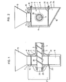
- the extruder comprises a cylinder 1 in which a screw 4 rotates, formed of a core from which projects a thread 3 which in the embodiment described here is a single thread with constant pitch.
- the screw could thus have any arrangement with a single or multiple thread, of constant or variable pitch, the top 29 of the thread or threads delimiting an imaginary cylindrical surface, the diameter of which is less than that of the smooth and cylindrical internal face 2 of the cylinder, so that there are one or more sets of predetermined thickness between the thread or threads of the screw and the internal face 2 of the cylinder 1.
- the cylinder 1 Upstream, the cylinder 1 is ends with a flat wall 5 perpendicular to the common axis of the screw 4 and of the cylinder 1.
- This wall 5 forms the downstream wall of a supply chamber generally designated by 6 and limited on the upstream side by a second wall plane 7 parallel to the wall 5.
- the supply chamber 6 is limited by two vertical walls 8 and 9 plane and parallel to the common axis of the screw 4 and cylinder 1, while an upper wall 10 has an opening e 11 in which is engaged the lower part 12 of a hopper 13 of usual construction which may be of pyramidal or conical shape and made of welded sheet.
- the supply chamber 6 communicates with an evacuation well 14 limited by an oblique bottom 15 and by the lower extensions of the walls 5 and 7.
- a first shutter 16 consisting for example of a flat sheet whose front edge is bent at 17 is engaged in horizontal grooves 18 and 19 formed on the internal side in the walls 5 and 7.
- This shutter 16 closes in its position commitment shown in the drawing the lower opening of the hopper 13, while in the disengaging position, it releases this opening, so that the plastic granules contained in the hopper 13 can flow into the chamber 6.
- the evacuation well 14 can be separated from the supply chamber 6 by a second shutter 20 also constituted by a flat sheet whose front edge is bent at 21, this sheet being engaged in grooves 22 and 23 formed in the walls 5 and 7 below the screw, but above the opening 24 of the evacuation well.
- a second shutter 20 also constituted by a flat sheet whose front edge is bent at 21, this sheet being engaged in grooves 22 and 23 formed in the walls 5 and 7 below the screw, but above the opening 24 of the evacuation well.
- the feed chamber and the hopper 13 define a space which can be completely filled by the plastic material intended to be treated by the extruder.
- This space has a symmetrical shape with respect to a vertical plane containing the axis of the screw and the distance between any of the walls which laterally limit the feed chamber and the top surface of the screw thread is at all points of an order of magnitude greater than the size of the granules. This distance will be, for example, a few centimeters, while the size of the granules is a few millimeters.
- the distance between the walls of the chamber 6 and the top 29 of the thread 3 of the screw must be at least higher licheou e at the depth of the groove of the screw or to the height of the net 3. noticed that, under certain conditions, the walls of the feeding chamber did not influence the behavior of the particles contained in this chamber.
- the particles are driven by the screw in an absolutely regular and symmetrical manner without exerting any lateral thrust on the screw, regardless of its angular position.
- the cylinder of the extruder may comprise upstream of the supply chamber 6 a bearing 25 guiding in rotation the end of the shaft 26 that the screw has at its upstream end.
- This bearing serving above all for sealing, it does not need to absorb a large axial thrust exerted on the screw.
- the thread of the screw 4 extends into the feed chamber 6 without change from the arrangement found in the cylinder 1.
- the top 29 of the thread 3 is contained in the same imaginary cylindrical surface as that which defines the turns of this thread in cylinder 1.
- the thread 3 extends axially to the wall 7, the opening for the passage of the screw is adjusted to the diameter of its core.
- the frame 27 of the drive device encloses, in a normal manner for example a pulley with multiple grooves allowing the drive of the screw 4 from a motor by means of belts or, alternatively, a gear.
- the presence of a large and symmetrically shaped feed chamber upstream of the extruder not only ensures the elimination of lateral thrust on the screw, but also has other advantages.
- the arrangement described makes it possible, thanks to the removable bottom 20 communicating with the evacuation well 14 and the shutter 16 closing the hopper 13, to carry out more easily than until now, certain operations intervening during the operation of the extruder.
- the moment at which this change takes place can be determined with great precision.
- the plastic supply chamber can be completely emptied hold and replace it with the new plastic mixed with the new dye. In this way, the product which is collected in the extrusion head placed at the outlet of the extruder exhibits a color change at a perfectly determined location.
Landscapes
- Engineering & Computer Science (AREA)
- Mechanical Engineering (AREA)
- Processing And Handling Of Plastics And Other Materials For Molding In General (AREA)
- Extrusion Moulding Of Plastics Or The Like (AREA)
Abstract
Description
- La présente invention a pour objet une extrudeuse pour matière plastique comprenant une vis pourvue d'un filetage saillant de diamètre prédéterminé, un cylindre disposé horizontalement et présentant un alésage ajusté avec un jeu prédéterminé au dit diamètre et une trémie placée au-dessus du cylindre et destiné à recevoir ladite matière plastique en particules dans un état intial.
- On sait que les extrudeuses sont des machines essentiellement destinées à travailler la matière plastique pour l'amener dans un état lui permettant d'être mise en forme par passage à travers un outillage d'extrusion ou par refoulement dans un moule. Elles se distinguent donc des machines qui sont conçues pour effectuer des opérations de mélange de divers constituants ou des opérations de pétrissage. Des machines de ces derniers types sont décrites par exemple dans les fascicules du brevet allemand No 880 935 et de la demande publiée DOS 2 024 596.
- Selon ces documents, la trémie communique avec l'enveloppe d'une zone amont de la machine, qui comporte dans un cas un agencement d'aubes de grandes dimensions, solidaires de la partie amont de la vis et dans l'autre cas un piston solidaire de la vis, celle-ci étant mobile non seulement en rotation mais également dans le sens axial de manière à comprimer la matière plastique en provenance de la trémie, contre la paroi amont de l'entrée du cylindre.
- Dans les extrudeuses à vis du genre mentionné au début, le cylindre présente en général à son extrémité amont une ouverture de forme rectangulaire, carrée ou ronde ou un raccord tubulaire vertical, et la trémie, généralement une pièce de tôle, est fixée dans cette ouverture ou ce raccord. Dans certains cas, l'ouverture d'alimentation est décalée latéralement par rapport à un plan vertical contenant l'axe de la vis ou bien on prévoit dans le cylindre une volute en forme de spirale destinée à guider la masse des particules de matière plastique qui est progressivement entraînée par la vis dans l'alésage du cylindre.
- La fig. 1 du brevet CH 612 375 montre par exemple que les dimensions internes du cylindre dans la zone de raccordement à la trémie sont du même ordre que celles de l'alésage du cylindre.
- Du fait de la forme asymétrique de l'espace à partir duquel les granules ou la poudre de la matière plastique à l'état initial, sont entraînés dans le cylindre, la vis est soumise à une poussée latérale qui, dans bien des cas, ne peut pas être absorbée par le ou les paliers, de sorte que les filets de la vis appuient à certains endroits contre la surface interne du cylindre. Cela conduit à une usure progressive des pièces et par conséquent à une variation des jeux existant entre la partie mobile et la partie fixe de l'extrudeuse.
- Pour remédier à ce défaut, une extrudeuse connue par le brevet français no 1 377 457 comporte dans sa partie amont située sous la trémie deux éléments de cylindre qui sont mobiles latéralement par rapport à la partie amont de la vis. Une fois que la matière contenue dans la trémie a pénétré entre ces parties du cylindre celles-ci sont déplacées l'une vers l'autre en comprimant la charge de matière plastique contre le noyau de la vis, entre les spires de son filet. Le fonctionnement de cette extrudeuse est donc essentiellement discontinu.
- Dans les extrudeuses usuelles, à fonctionnement continu, les dimensions restreintes des ouvertures d'alimentation font apparaître un autre phénomène très gênant: Le débit de l'extrudeuse présente des irrégularités dans le temps, qu'on nomme pulsations. A chaque tour de vis, le débit varie si bien que le produit extrudé présente des vagues longitudinales. Or, aujour'hui, dans bien des cas, une grande précision est demandée, ce qui rend les extrudeuses ordinaires impropres.
- Les pulsations du débit proviennent du filet de la vis passant à proximité des parois, notamment du fond de l'ouverture d'alimentation. En effet, la masse de granulés prise entre le noyau de la vis, le filet de la vis et .le fond de l'ouverture d'alimentation est poussée vers l'aval dans le cylindre. Lorsqu'au contraire, le filet de la vis se trouve dans le haut de l'ouverture d'alimentation, il déplace une masse de granulés libre de se mouvoir dans n'importe quelle direction. Des capteurs de pression montés le long du cylindre montrent des variations périodiques avec la rotation de la vis.
- Le but de la présente invention est de créer un agencement d'une extrudeuse à vis du genre mentionné au début, qui permette une production continue et absolument régulière de matière plastique homogénéisée en évitant les défauts mentionnés ci-dessus.
- Pour cela, l'extrudeuse selon l'invention est caractérisée en ce qu'elle comprend une chambre d'alimentation située sous la trémie, communiquant avec celle-ci et limitée par un ensemble de parois fixes, celles-ci étant disposées symétriquement par rapport à un plan vertical contenant l'axe commun de la vis et du cylindre, entourant une partie amont de la vis et présentant des faces internes parallèles audit axe et située à-une-distance dudit filetage qui est en tout point supérieure audit jeu et suffisante pour que lesdites parois n'exercent aucune influence sur les particules de matière plastique contenues dans ladite chambre d'alimentation.
- Dans cette disposition, les granulés sont poussés vers l'aval dans des conditions telles que, mises à part les forces de gravitation qui sont ici négligeables, la position du filet de la vis ne joue pas de rôle. On a ainsi une poussée régulière des granulés vers l'aval, quelle que soit la position angulaire de la vis.
- On va décrire ci-après, à titre d'exemple, une forme d'exécution de l'extrudeuse selon l'invention dont la partie amont est représentée, au dessin annexé.
- à la fig. 1 en coupe longitudinale, et
- à la fig. 2 en coupe transversale.
- L'extrudeuse comporte un cylindre 1 dans lequel tourne une vis 4, formée d'un noyau dont fait saillie un filet 3 qui dans la forme d'exécution décrite ici est un filet unique à pas constant. Cependant, il est bien entendu que la vis pourrait ainsi présenter n'importe quelle disposition avec filet simple ou multiple, de pas constant ou variable, le sommet 29 du ou des filets délimitant une surface cylindrique imaginaire, dont le diamètre est inférieur à celui de la face interne lisse et cylindrique 2 du cylindre, de sorte qu'il existe un ou des jeux d'épaisseur prédéterminée entre le ou les filets de la vis et la face interne 2 du cylindre 1. A l'amont, le cylindre 1 se termine par une paroi plane 5 perpendiculaire à l'axe commun de la vis 4 et du cylindre 1. Cette paroi 5 forme la paroi aval d'une chambre d'alimentation désignée de façon générale par 6 et limitée du côté amont par une seconde paroi plane 7 parallèle à la paroi 5. Dans le sens latéral, comme on le voit à la fig, 2, la chambre d'alimentation 6 est limitée par deux parois verticales 8 et 9 planes et parallèles à l'axe commun de la vis 4 et du cylindre 1, tandis qu'une paroi supérieure 10 comporte une ouverture 11 dans laquelle est engagée la partie inférieure 12 d'une trémie 13 de construction usuelle qui peut être de forme pyramidale ou cônique et constituée en tôle soudée. A sa partie inférieure, la chambre d'alimentation 6 communique avec un puits d'évacuation 14 limité par un fond oblique 15 et par les prolongements inférieurs des parois 5 et 7.
- Un premier obturateur 16, constitué par exemple d'une tôle plane dont le bord avant est coudé en 17 est engagé dans des rainures horizontales 18 et 19 ménagées du côté interne dans les parois 5 et 7. Cet obturateur 16 ferme dans sa position d'engagement représentée au dessin l'ouverture inférieure de la trémie 13, tandis qu'en position de dégagement, il libère cette ouverture, de sorte que les granulés de matière plastique contenus dans la trémie 13 peuvent s'écouler dans la chambre 6.
- D'autre part, le puits d'évacuation 14 peut être séparé de la chambre d'alimentation 6 par un second obturateur 20 également constitué par une tôle plane dont le bord avant est coudé en 21, cette tôle étant engagée dans des rainures 22 et 23 ménagées dans les parois 5 et 7 en dessous de la vis, mais au-dessus de l'ouverture 24 du puits d'évacuation.
- Comme on le voit au dessin, lorsque le fond amovible 20 de la chambre d'alimentation 6 est en place et que l'obturateur 16 est ouvert, la chambre d'alimentation et la trémie 13 délimitent un espace qui peut être entièrement rempli par la matière plastique destinée à être traitée par l'extrudeuse. Cet espace a une forme symétrique par rapport à un plan vertical contenant l'axe de la vis et la distance entre n'importe laquelle des parois qui limitent latéralement la chambre d'alimentation et la surface sommitale du filet de la vis est en tout point d'un ordre de grandeur supérieur à la dimension des granulés. Cette distance sera, par exemple, de quelques centimètres, alors que la dimension des granulés est de quelques millimètres.
- On peut dire aussi que la distance entre les parois de la chambre 6 et le sommet 29 du filet 3 de la vis doit être au moins égaleou supérieureà la profondeur de la rainure de la vis ou encore à la hauteur du filet 3. On a remarqué que, dansées conditions, les parois de la chambre d'alimentation n'influençaient pas le comportement des particules contenues dans cette chambre. L'entraînement des particules par la vis se fait d'une façon absolument régulière et symétrique sans exercer aucune poussée latérale sur la vis, indépendamment de sa position angulaire.
- Ainsi, le cylindre de l'extrudeuse, peut comporter à l'amont de la chambre d'alimentation 6 un palier 25 guidant en rotation le bout d'arbre 26 que la vis présente à son extrémité amont. Ce palier servant avant tout à l'étanchéité, il n'a pas besoin d'absorber une grande poussée axiale s'exerçant sur la vis.
- Le filetage de la vis 4 se prolonge dans la chambre d'alimentation 6 sans changement par rapport à la disposition que l'on trouve dans le cylindre 1. Ainsi, le sommet 29 du filet 3 est contenu dans la même surface cylindrique imaginaire que celle qui définit les spires de ce filet dans le cylindre 1. Comme on le voit à la fig. 1, le filet 3 s'étend dans le sens axial jusqu'à la paroi 7 dont l'ouverture destinée au passage de la vis est ajustée au diamètre de son noyau.
- Le bâti 27 du dispositif d'entraînement enferme, de façon normale par exemple une poulie à gorges multiples permettant l'entraînement de la vis 4 à partir d'un moteur par le moyen de courroies ou, en variante, un engrenage.
- La présence d'une chambre d'alimentation de grandes dimensions et de forme symétrique à l'amont de l'extrudeuse n'assure pas seulement l'élimination de la poussée latérale sur la vis, mais présente encore d'autres avantages. Ainsi, la disposition décrite permet grâce au fond amovible 20 communiquant avec le puits d'évacuation 14 et à l'obturateur 16 fermant la trémie 13, de réaliser plus facilement que jusqu'à maintenant, certaines opérations intervenant au cours du fonctionnement de l'extrudeuse. Ainsi, notamment, lorsqu'il est nécessaire de changer de matière ou de modifier certaines caractéristiques de la matière plastique introduite dans la machine par exemple de changer le colorant qu'elle contient, le moment auquel ce changement a lieu peut être déterminé avec grande précision, étant donné qu'on peut vider entièrement la chambre d'alimentation de la matière plastique qu'elle contient et remplacer celle-ci par la nouvelle matière plastique mélangée au nouveau colorant. De cette façon, le produit que l'on recueille dans la tête d'extrusion placée à la sortie de l'extrudeuse présente un changement de couleur à un endroit parfaitement déterminé.
Claims (8)
Applications Claiming Priority (2)
| Application Number | Priority Date | Filing Date | Title |
|---|---|---|---|
| CH738581 | 1981-11-17 | ||
| CH7385/81 | 1981-11-17 |
Publications (2)
| Publication Number | Publication Date |
|---|---|
| EP0079656A1 true EP0079656A1 (fr) | 1983-05-25 |
| EP0079656B1 EP0079656B1 (fr) | 1985-09-11 |
Family
ID=4324319
Family Applications (1)
| Application Number | Title | Priority Date | Filing Date |
|---|---|---|---|
| EP82201429A Expired EP0079656B1 (fr) | 1981-11-17 | 1982-11-11 | Extrudeuse pour matière plastique |
Country Status (5)
| Country | Link |
|---|---|
| US (1) | US4491418A (fr) |
| EP (1) | EP0079656B1 (fr) |
| JP (1) | JPS5889340A (fr) |
| DE (1) | DE3266229D1 (fr) |
| FI (1) | FI72077C (fr) |
Families Citing this family (3)
| Publication number | Priority date | Publication date | Assignee | Title |
|---|---|---|---|---|
| US6306319B1 (en) | 1999-07-19 | 2001-10-23 | Chroma Corporation | Method of determining wear |
| CN104249418B (zh) * | 2014-07-18 | 2017-01-11 | 江苏绿艳高分子材料有限公司 | 一种tpu生产喂料装置 |
| RU207774U1 (ru) * | 2020-02-18 | 2021-11-16 | Общество с ограниченной ответственностью "ПЛЮС 1" | Устройство по изготовлению пеллетов |
Citations (2)
| Publication number | Priority date | Publication date | Assignee | Title |
|---|---|---|---|---|
| DE880935C (de) * | 1938-08-02 | 1953-06-25 | Werner & Pfleiderer | Knet- und Mischmaschine fuer Rohgummi od. dgl. |
| FR1377457A (fr) * | 1963-09-23 | 1964-11-06 | Grosfillex Sarl | Extrudeuse à grande surface d'alimentation |
Family Cites Families (7)
| Publication number | Priority date | Publication date | Assignee | Title |
|---|---|---|---|---|
| US1326375A (en) * | 1917-06-09 | 1919-12-30 | Spencer Turbine Co | Rubber-working machine. |
| CH515738A (de) * | 1969-05-23 | 1971-11-30 | Henrik Dipl Ing Nielaender | Misch- und Plastifiziervorrichtung sowie Verfahren zum Betrieb derselben |
| GB1369445A (en) * | 1971-03-29 | 1974-10-09 | Baker Perkins Ltd | Method and apparatus for preparing foundry moulds and cores |
| US3901483A (en) * | 1973-07-13 | 1975-08-26 | William Lasar | Method and apparatus for mixing materials, including ground meat |
| GB1553196A (en) * | 1975-08-20 | 1979-09-26 | London Brick Buildings Ltd | Mixer for and method of mixing particulate constituents |
| CH612375A5 (fr) * | 1977-03-29 | 1979-07-31 | Maillefer Sa | |
| DE2721169C2 (de) * | 1977-05-11 | 1985-12-05 | Draiswerke Gmbh, 6800 Mannheim | Verfahren und Anlage zum Aufbereiten von Thermoplasten oder Duroplasten |
-
1982
- 1982-11-09 US US06/440,430 patent/US4491418A/en not_active Expired - Fee Related
- 1982-11-11 DE DE8282201429T patent/DE3266229D1/de not_active Expired
- 1982-11-11 EP EP82201429A patent/EP0079656B1/fr not_active Expired
- 1982-11-12 FI FI823885A patent/FI72077C/fi not_active IP Right Cessation
- 1982-11-16 JP JP57200988A patent/JPS5889340A/ja active Granted
Patent Citations (2)
| Publication number | Priority date | Publication date | Assignee | Title |
|---|---|---|---|---|
| DE880935C (de) * | 1938-08-02 | 1953-06-25 | Werner & Pfleiderer | Knet- und Mischmaschine fuer Rohgummi od. dgl. |
| FR1377457A (fr) * | 1963-09-23 | 1964-11-06 | Grosfillex Sarl | Extrudeuse à grande surface d'alimentation |
Also Published As
| Publication number | Publication date |
|---|---|
| JPS5889340A (ja) | 1983-05-27 |
| JPS6238131B2 (fr) | 1987-08-17 |
| FI823885A0 (fi) | 1982-11-12 |
| US4491418A (en) | 1985-01-01 |
| FI72077B (fi) | 1986-12-31 |
| FI72077C (fi) | 1988-07-12 |
| FI823885L (fi) | 1983-05-18 |
| DE3266229D1 (en) | 1985-10-17 |
| EP0079656B1 (fr) | 1985-09-11 |
Similar Documents
| Publication | Publication Date | Title |
|---|---|---|
| FR2492491A1 (fr) | ||
| CH404942A (fr) | Malaxeur continu | |
| EP2673075B1 (fr) | Dispositif de traitement en continu d'au moins une matiere premiere, installation de traitement et utilisation d'un tel dispositif | |
| WO2018087467A1 (fr) | Ensemble d'extrusion volumetrique pour melanges d'elastomeres | |
| EP0079656B1 (fr) | Extrudeuse pour matière plastique | |
| CH643179A5 (fr) | Dispositif d'injection de matieres plastiques ou elastomeres. | |
| FR2519289A1 (fr) | Appareil rotatif a plusieurs etages, pour le traitement a debit reglable d'une matiere polymere ou plastique | |
| EP0006073B1 (fr) | Extracteur doseur pour produits pulvérulents | |
| EP0592312B1 (fr) | Doseur, robinet doseur, appareil de dosage en cadence de liquide | |
| EP0567367B1 (fr) | Procédé pour le transport pneumatique de matériaux en vrac, tels que mortier de chape, béton, sable ... et transporteur-malaxeur mettant en oeuvre ce procédé | |
| FR2932697A1 (fr) | Dispositif d'agitation et son procede de reglage | |
| WO2017064197A1 (fr) | Machine hydraulique et pompe doseuse reversible equipee d'une telle machine | |
| EP0400496A1 (fr) | Pompe volumétrique et procédé pour pomper volumétriquement | |
| EP3022038B1 (fr) | Dispositif et procédé d'extrusion de mélanges d'élastomères | |
| FR2482874A1 (fr) | Brides de fixation de fermeture d'extremite de bol de centrifugeur | |
| EP0677371B1 (fr) | Ensemble clapet pointe de vis à goupille | |
| FR2942168A1 (fr) | Dispositif de production de granules pour presse de trituration de graines oleagineuses a vis continue | |
| FR2515102A1 (fr) | Dispositif de barrage contre un ecoulement en retour pour un extrudeur a vis sans fin | |
| FR2963781A1 (fr) | Installation de distribution de produits et dispositif de distribution pour une telle installation | |
| FR2496002A1 (fr) | Dispositif melangeur et homogeneiseur pour presses a injecter et extrudeuses pour matieres thermoplastiques | |
| FR3106047A1 (fr) | Machine de preparation de boisson infusee munie d’une carafe agencee sur une base de reception | |
| EP4301981B1 (fr) | Procede et pompe de dosage proportionnel a faible debit | |
| FR2610074A1 (fr) | Attenuateur de bruit pour robinets, en particulier pour mitigeurs a disques ceramiques | |
| WO2003016024A1 (fr) | Pompe volumetrique | |
| FR2730950A1 (fr) | Dispositif pour fabriquer un tuyau nervure |
Legal Events
| Date | Code | Title | Description |
|---|---|---|---|
| PUAI | Public reference made under article 153(3) epc to a published international application that has entered the european phase |
Free format text: ORIGINAL CODE: 0009012 |
|
| AK | Designated contracting states |
Designated state(s): CH DE FR GB IT LI SE |
|
| 17P | Request for examination filed |
Effective date: 19830709 |
|
| ITF | It: translation for a ep patent filed | ||
| GRAA | (expected) grant |
Free format text: ORIGINAL CODE: 0009210 |
|
| AK | Designated contracting states |
Designated state(s): CH DE FR GB IT LI SE |
|
| REF | Corresponds to: |
Ref document number: 3266229 Country of ref document: DE Date of ref document: 19851017 |
|
| PLBI | Opposition filed |
Free format text: ORIGINAL CODE: 0009260 |
|
| 26 | Opposition filed |
Opponent name: OY NOKIA AB Effective date: 19860610 |
|
| PLBM | Termination of opposition procedure: date of legal effect published |
Free format text: ORIGINAL CODE: 0009276 |
|
| STAA | Information on the status of an ep patent application or granted ep patent |
Free format text: STATUS: OPPOSITION PROCEDURE CLOSED |
|
| 27C | Opposition proceedings terminated |
Effective date: 19880213 |
|
| PGFP | Annual fee paid to national office [announced via postgrant information from national office to epo] |
Ref country code: SE Payment date: 19921029 Year of fee payment: 11 |
|
| ITTA | It: last paid annual fee | ||
| PGFP | Annual fee paid to national office [announced via postgrant information from national office to epo] |
Ref country code: FR Payment date: 19931011 Year of fee payment: 12 |
|
| PGFP | Annual fee paid to national office [announced via postgrant information from national office to epo] |
Ref country code: GB Payment date: 19931013 Year of fee payment: 12 |
|
| PGFP | Annual fee paid to national office [announced via postgrant information from national office to epo] |
Ref country code: DE Payment date: 19931020 Year of fee payment: 12 |
|
| PGFP | Annual fee paid to national office [announced via postgrant information from national office to epo] |
Ref country code: CH Payment date: 19931110 Year of fee payment: 12 |
|
| PG25 | Lapsed in a contracting state [announced via postgrant information from national office to epo] |
Ref country code: SE Effective date: 19931112 |
|
| PG25 | Lapsed in a contracting state [announced via postgrant information from national office to epo] |
Ref country code: GB Effective date: 19941111 |
|
| PG25 | Lapsed in a contracting state [announced via postgrant information from national office to epo] |
Ref country code: LI Effective date: 19941130 Ref country code: CH Effective date: 19941130 |
|
| EUG | Se: european patent has lapsed |
Ref document number: 82201429.6 Effective date: 19940610 |
|
| GBPC | Gb: european patent ceased through non-payment of renewal fee |
Effective date: 19941111 |
|
| PG25 | Lapsed in a contracting state [announced via postgrant information from national office to epo] |
Ref country code: FR Effective date: 19950731 |
|
| REG | Reference to a national code |
Ref country code: CH Ref legal event code: PL |
|
| PG25 | Lapsed in a contracting state [announced via postgrant information from national office to epo] |
Ref country code: DE Effective date: 19950801 |
|
| REG | Reference to a national code |
Ref country code: FR Ref legal event code: ST |