EP0079849A2 - Lampe à vapeur à basse pression - Google Patents
Lampe à vapeur à basse pression Download PDFInfo
- Publication number
- EP0079849A2 EP0079849A2 EP82730134A EP82730134A EP0079849A2 EP 0079849 A2 EP0079849 A2 EP 0079849A2 EP 82730134 A EP82730134 A EP 82730134A EP 82730134 A EP82730134 A EP 82730134A EP 0079849 A2 EP0079849 A2 EP 0079849A2
- Authority
- EP
- European Patent Office
- Prior art keywords
- burner
- cladding tube
- low
- flat burner
- flat
- Prior art date
- Legal status (The legal status is an assumption and is not a legal conclusion. Google has not performed a legal analysis and makes no representation as to the accuracy of the status listed.)
- Granted
Links
Images

Classifications
-
- H—ELECTRICITY
- H01—ELECTRIC ELEMENTS
- H01J—ELECTRIC DISCHARGE TUBES OR DISCHARGE LAMPS
- H01J61/00—Gas-discharge or vapour-discharge lamps
- H01J61/02—Details
- H01J61/52—Cooling arrangements; Heating arrangements; Means for circulating gas or vapour within the discharge space
-
- H—ELECTRICITY
- H01—ELECTRIC ELEMENTS
- H01J—ELECTRIC DISCHARGE TUBES OR DISCHARGE LAMPS
- H01J61/00—Gas-discharge or vapour-discharge lamps
- H01J61/70—Lamps with low-pressure unconstricted discharge having a cold pressure < 400 Torr
Definitions
- the invention relates to a low-pressure vapor lamp, especially mercury low-pressure vapor lamp with mixed burner as F formed lamp tube, which is surrounded by a cladding tube.
- low-pressure steam lamps of this type usually consist of a quartz tube filled with metal vapor with a vapor pressure of, for example, 0.1 Torr, with two electrodes at the ends, the lamp tube being designed with an oblong-flat cross section, for which reason the term "flat-burner" is also used.
- Low-pressure vapor lamps have a very large proportion of low-pressure mercury lamps because they are very suitable devices for generating UV radiation.
- the light they emit is namely a pure line spectrum, which has a high UV component and has a particularly strong line at 254 nm.
- the flat burner is usually surrounded by a jacket tube also made of quartz, and the burner arrangement consisting of jacket tube and flat burner can then be immersed in water to be sterilized.
- the cladding tube is designed as a round tube because it provides optimal protection against the surrounding water pressure.
- the flat burner itself located in the cladding tube can therefore be built relatively thin-walled.
- the flat burner also produces a line spectrum - albeit not as intense - with 183 nm, which can be used to generate ozone that supports the sterilization and sterilization process.
- the invention is therefore based on the object, while avoiding the disadvantages described, of creating a low-pressure vapor lamp in which an increase in the radiation intensity is possible with simple means.
- the invention achieves this goal in an astonishingly simple manner in that the flat burner is at least partially in contact with the inner wall of the cladding tube.
- the invention is based on the surprising finding that, by touching the flat burner with the cladding tube, cooling can take place through the medium surrounding the cladding tube and to be sterilized or sterilized. As has been found in experiments, this so-called "contact cooling” can achieve a considerable increase in the radiation intensity. This is all the more surprising since both the cladding tube and the jacket of the flat burner each consist of quartz - a poor heat conductor. The gas in the flat burner obviously cools at the points of contact of the Flat burner with the cladding tube so far that a higher energy supply and thus a higher emitted radiation intensity is possible.
- the contact is linear in the direction of the longitudinal axes of the flat burner and the cladding tube, so that there is practically a contact line along the surface of the flat burner.
- a linear contact with the cladding tube cannot always be realized for manufacturing reasons, since both the inside wall of the cladding tube and the outside wall of the flat burner may have slight unevenness.
- the contact is limited to a large number of discrete points of contact. But here too, tests have led to the astonishing result that even then there is sufficient contact cooling, so that one can do without the complex external cooling.
- the flat burner is provided with several sleeves, which are arranged around the outer wall and brought into contact with the cladding tube.
- the flat burner is arranged to be displaceable transversely to its longitudinal axis within the cladding tube and can be fixed in different positions. In its one position - transport position - the flat burner is located in the middle in a known manner inside the cladding tube, so that contact with the cladding tube is avoided. After transport and commissioning, the flat burner is then moved to the other position and fixed where it is in the desired contact with the cladding tube.
- the novel contact cooling created by the invention can be so effective that when switching on the low pressure lamp u.
- the optimal operating temperature of the gas in the flat burner may not be reached. Therefore, a further expedient embodiment of the invention provides the possibility of not allowing the desired contact cooling to take effect until a certain temperature has been reached.
- a bimetal can be used which, when a predetermined temperature value is reached, causes the flat burner to be moved into a position in which the flat burner is in contact with the cladding tube.
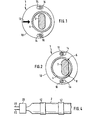
- the low pressure lamp 1 shown in the drawing comprises a flat burner 2 with an elongated flat cross section.
- the flat burner 2 the outer wall of which is made of quartz, is surrounded in the usual way by a round cladding tube 4 - also made of quartz.
- a reaction chamber 28 adjoins the cladding tube (see FIG. 3), which receives the medium, for example water, which is to be subjected to UV radiation for the purpose of disinfection and sterilization.
- the medium for example water
- FIG. 3 a total of four cladding tubes 4, each at an angle of 90 ° to one another, with flat burners 2 located therein are provided, two of which can be seen in the cross-sectional illustration.
- a sensor 18 for the UV radiation occurring at this point.
- the reactor 30, which is constructed in a manner known per se, has a cover 32 and a housing 40.
- the cladding tubes 4 are held within a flange 34 which is connected to a flange ring 36 via a screw connection 38. Seals 24 and 26 are provided for sealing the reaction space 28.
- each flat burner 2 has at its outer ends a base 20 with electrodes 22 for the flat burner 2 (in the figures only one end of the flat burner 2 is in each case) shown, so that only one base 20 'can be seen in each case).
- the flat burners 2 located within the cladding tubes 4 are now held over a disk-shaped burner holder 10, which is arranged at the two ends of the cladding tube 4.
- the flat burner 2 is connected to the two burner holders 10 at the outer ends via the electrodes 2 which engage in corresponding openings in the burner holder 10.
- the burner holder 10 - and thus, of course, the flat burner 2 connected to them - can be displaced both to the left and to the right in a direction indicated by the arrow 12.
- the direction of displacement is preferably selected transversely to the direction in which the flat burner 2 extends with its elongated cross section.
- the burner holders 10 are each provided with two elongated holes 14 which extend in the direction of the arrow 12.
- a pin 16 engages in each elongated hole 14, as a result of which clear guidance is achieved during the displacement of the burner holder 10.
- two different end positions of the burner holder 10 are marked by the pins 16 which are arranged in a fixed position relative to the burner holders 10, namely when the pins 16 are located at one end or at the other end of the elongated hole.
- the burner holder 10 can be fixed in the two end positions by screws, not shown, so that the flat burner is also firmly held in the two different positions.
- the burner holder 10 is in a first fixed position, to which a central arrangement of the flat burner 2 within the tube 4 is assigned.
- transport can also be carried out without any problems, since the flat burner 2 is not in contact with the tubular tube 4.
- the length of the elongated holes 14 is chosen taking into account the diameter of the pins 16 so that - starting from the position in FIG. 1 - when the burner holder 10 is moved in the direction of the arrow 12, the flat burner 2 comes into contact with the cladding tube 4, without causing damage.
- the flat burner 2 is surrounded by sleeves 42 arranged at a distance from one another.
- the flat burner 2 can be shifted so far by means of the burner holder 10 that the sleeves 42 rest against the inner wall of the cladding tube 4, which then also results in the desired contact cooling.
Landscapes
- Vessels And Coating Films For Discharge Lamps (AREA)
- Eye Examination Apparatus (AREA)
- Cold Air Circulating Systems And Constructional Details In Refrigerators (AREA)
- Display Devices Of Pinball Game Machines (AREA)
- Apparatus For Disinfection Or Sterilisation (AREA)
Priority Applications (1)
| Application Number | Priority Date | Filing Date | Title |
|---|---|---|---|
| AT82730134T ATE26769T1 (de) | 1981-11-12 | 1982-11-10 | Niederdruckdampflampe. |
Applications Claiming Priority (2)
| Application Number | Priority Date | Filing Date | Title |
|---|---|---|---|
| DE19813144925 DE3144925A1 (de) | 1981-11-12 | 1981-11-12 | Niederdruckdampflampe |
| DE3144925 | 1981-11-12 |
Publications (3)
| Publication Number | Publication Date |
|---|---|
| EP0079849A2 true EP0079849A2 (fr) | 1983-05-25 |
| EP0079849A3 EP0079849A3 (en) | 1984-04-25 |
| EP0079849B1 EP0079849B1 (fr) | 1987-04-22 |
Family
ID=6146215
Family Applications (1)
| Application Number | Title | Priority Date | Filing Date |
|---|---|---|---|
| EP82730134A Expired EP0079849B1 (fr) | 1981-11-12 | 1982-11-10 | Lampe à vapeur à basse pression |
Country Status (4)
| Country | Link |
|---|---|
| EP (1) | EP0079849B1 (fr) |
| AT (1) | ATE26769T1 (fr) |
| CA (1) | CA1205508A (fr) |
| DE (2) | DE3144925A1 (fr) |
Family Cites Families (2)
| Publication number | Priority date | Publication date | Assignee | Title |
|---|---|---|---|---|
| US4071799A (en) * | 1977-04-01 | 1978-01-31 | Xerox Corporation | Sodium vapor lamp with emission aperture |
| DE2825018C2 (de) * | 1978-06-05 | 1986-07-24 | Georg 4902 Bad Salzuflen Horstmann | Quecksilberdampf-Niederdrucklampe |
-
1981
- 1981-11-12 DE DE19813144925 patent/DE3144925A1/de not_active Withdrawn
-
1982
- 1982-11-10 EP EP82730134A patent/EP0079849B1/fr not_active Expired
- 1982-11-10 AT AT82730134T patent/ATE26769T1/de not_active IP Right Cessation
- 1982-11-10 DE DE8282730134T patent/DE3276144D1/de not_active Expired
- 1982-11-12 CA CA000415483A patent/CA1205508A/fr not_active Expired
Also Published As
| Publication number | Publication date |
|---|---|
| EP0079849A3 (en) | 1984-04-25 |
| DE3276144D1 (en) | 1987-05-27 |
| ATE26769T1 (de) | 1987-05-15 |
| CA1205508A (fr) | 1986-06-03 |
| DE3144925A1 (de) | 1983-06-16 |
| EP0079849B1 (fr) | 1987-04-22 |
Similar Documents
| Publication | Publication Date | Title |
|---|---|---|
| DE3323637C2 (de) | Anordnung zum Betrieb einer langgestreckten elektrodenlosen Lampe | |
| DE3011382C2 (de) | Niederdruckgasentladungslampe | |
| EP0772900B1 (fr) | Systeme de decharge pour lasers a gaz impulsionnels | |
| DE2622993A1 (de) | Uv-lampen-anordnung | |
| DE1298175B (de) | Schaltfunkenstrecke von geringer Eigeninduktivitaet | |
| DE3929285C2 (fr) | ||
| DE2813860A1 (de) | Eintank-roentgengenerator | |
| EP0602505B1 (fr) | Appareil pour le traitement de liquides chargés de polluants par rayonnement UV | |
| EP1525646B1 (fr) | Laser a decharge gazeuse | |
| DE19613468A1 (de) | Quecksilber-Niederdruckentladungslampe | |
| EP0079849B1 (fr) | Lampe à vapeur à basse pression | |
| DE3208519C2 (fr) | ||
| DE8133065U1 (de) | Niederdruckdampflampe | |
| DE2002374A1 (de) | Gasentladungsroehre fuer einen Laser | |
| DE2057125A1 (de) | Verfahren und Vorrichtung zum Stabih sieren eines Lichtbogens | |
| CH660253A5 (de) | Gasisolierter durchfuehrungsisolator. | |
| DE1100167B (de) | Verfahren zum Betrieb einer Entladungslampe grosser Lichtstaerke und Leuchtdichte sowie Hochdruckentladungslampe hierfuer | |
| EP4404985B1 (fr) | Purificateur d'air pour l'irradiation uv d'un air en circulation en particulier chargé de germes ou d'agents infectieux | |
| AT525380B1 (de) | Vorrichtung zur Flüssigkeitsdesinfektion | |
| DE1440661C (de) | Stromdurchführung fur Glimmentaldungs gefäße | |
| DE10130348B4 (de) | Anordnung zur UV-Bestrahlung von Flüssigkeiten und Gasen | |
| EP0315583A2 (fr) | Procédé et dispositif pour la stérilisation de fluides | |
| DE357578C (de) | Vorrichtung zum Behandeln von Fluessigkeiten mit ultravioletten Strahlen | |
| DE19728646C2 (de) | Tauchlampe für die Anregung photochemischer Reaktionen | |
| DE1440661B2 (de) | Stromdurchfuehrung fuer glimmentladungsgefaesse |
Legal Events
| Date | Code | Title | Description |
|---|---|---|---|
| PUAI | Public reference made under article 153(3) epc to a published international application that has entered the european phase |
Free format text: ORIGINAL CODE: 0009012 |
|
| AK | Designated contracting states |
Designated state(s): AT BE CH DE FR GB IT LI LU NL SE |
|
| PUAL | Search report despatched |
Free format text: ORIGINAL CODE: 0009013 |
|
| AK | Designated contracting states |
Designated state(s): AT BE CH DE FR GB IT LI LU NL SE |
|
| 17P | Request for examination filed |
Effective date: 19841023 |
|
| 17Q | First examination report despatched |
Effective date: 19860225 |
|
| GRAA | (expected) grant |
Free format text: ORIGINAL CODE: 0009210 |
|
| AK | Designated contracting states |
Kind code of ref document: B1 Designated state(s): AT BE CH DE FR GB IT LI LU NL SE |
|
| REF | Corresponds to: |
Ref document number: 26769 Country of ref document: AT Date of ref document: 19870515 Kind code of ref document: T |
|
| REF | Corresponds to: |
Ref document number: 3276144 Country of ref document: DE Date of ref document: 19870527 |
|
| ITF | It: translation for a ep patent filed | ||
| ET | Fr: translation filed | ||
| PG25 | Lapsed in a contracting state [announced via postgrant information from national office to epo] |
Ref country code: LU Free format text: LAPSE BECAUSE OF NON-PAYMENT OF DUE FEES Effective date: 19871130 |
|
| BECA | Be: change of holder's address |
Free format text: 870422 *HORSTMANN MARIANNE NEE SCHUBBE;*HORSTMANN INGRID;*HORSTMANN ECKHARD:GEIBELSTRASSE 2, D-4902 BAD SALZUFLEN;ANNABERGSTRASSE 2, D-5600 WUPPERTAL-BARMEN;SPELVAGEN 22, 14200TRANGSUND (SU?DE) |
|
| BECH | Be: change of holder |
Free format text: 870422 *HORSTMANN MARIANNE NEE SCHUBBE;*HORSTMANN INGRID;*HORSTMANN ECKHARD |
|
| PLBE | No opposition filed within time limit |
Free format text: ORIGINAL CODE: 0009261 |
|
| STAA | Information on the status of an ep patent application or granted ep patent |
Free format text: STATUS: NO OPPOSITION FILED WITHIN TIME LIMIT |
|
| REG | Reference to a national code |
Ref country code: CH Ref legal event code: PUE Owner name: MARIANNE HORSTMANN-SCHUEBBE |
|
| 26N | No opposition filed | ||
| GBPC | Gb: european patent ceased through non-payment of renewal fee | ||
| GBDL | Gb: delete "european patent ceased" from journal |
Free format text: 5186,PAGE 2156 |
|
| PGFP | Annual fee paid to national office [announced via postgrant information from national office to epo] |
Ref country code: GB Payment date: 19900823 Year of fee payment: 9 |
|
| PGFP | Annual fee paid to national office [announced via postgrant information from national office to epo] |
Ref country code: DE Payment date: 19901016 Year of fee payment: 9 |
|
| PGFP | Annual fee paid to national office [announced via postgrant information from national office to epo] |
Ref country code: CH Payment date: 19901108 Year of fee payment: 9 |
|
| PGFP | Annual fee paid to national office [announced via postgrant information from national office to epo] |
Ref country code: AT Payment date: 19901126 Year of fee payment: 9 |
|
| PGFP | Annual fee paid to national office [announced via postgrant information from national office to epo] |
Ref country code: SE Payment date: 19901127 Year of fee payment: 9 |
|
| ITTA | It: last paid annual fee | ||
| PGFP | Annual fee paid to national office [announced via postgrant information from national office to epo] |
Ref country code: NL Payment date: 19901130 Year of fee payment: 9 |
|
| PGFP | Annual fee paid to national office [announced via postgrant information from national office to epo] |
Ref country code: BE Payment date: 19901228 Year of fee payment: 9 |
|
| PG25 | Lapsed in a contracting state [announced via postgrant information from national office to epo] |
Ref country code: GB Effective date: 19911110 Ref country code: AT Effective date: 19911110 |
|
| PG25 | Lapsed in a contracting state [announced via postgrant information from national office to epo] |
Ref country code: SE Effective date: 19911111 |
|
| PGFP | Annual fee paid to national office [announced via postgrant information from national office to epo] |
Ref country code: FR Payment date: 19911127 Year of fee payment: 10 |
|
| PG25 | Lapsed in a contracting state [announced via postgrant information from national office to epo] |
Ref country code: LI Effective date: 19911130 Ref country code: CH Effective date: 19911130 Ref country code: BE Effective date: 19911130 |
|
| BERE | Be: lapsed |
Owner name: HORSTMANN ECKHARD Effective date: 19911130 Owner name: HORSTMANN INGRID Effective date: 19911130 Owner name: HORSTMANN MARIANNE NEE SCHUBBE Effective date: 19911130 |
|
| PG25 | Lapsed in a contracting state [announced via postgrant information from national office to epo] |
Ref country code: NL Effective date: 19920601 |
|
| GBPC | Gb: european patent ceased through non-payment of renewal fee | ||
| NLV4 | Nl: lapsed or anulled due to non-payment of the annual fee | ||
| REG | Reference to a national code |
Ref country code: CH Ref legal event code: PL |
|
| PG25 | Lapsed in a contracting state [announced via postgrant information from national office to epo] |
Ref country code: DE Effective date: 19920801 |
|
| PG25 | Lapsed in a contracting state [announced via postgrant information from national office to epo] |
Ref country code: FR Effective date: 19930730 |
|
| REG | Reference to a national code |
Ref country code: FR Ref legal event code: ST |
|
| EUG | Se: european patent has lapsed |
Ref document number: 82730134.2 Effective date: 19920604 |