EP0079882B1 - Dach mit schuppenartig sich überlappenden dachdekungselementen - Google Patents
Dach mit schuppenartig sich überlappenden dachdekungselementen Download PDFInfo
- Publication number
- EP0079882B1 EP0079882B1 EP81901526A EP81901526A EP0079882B1 EP 0079882 B1 EP0079882 B1 EP 0079882B1 EP 81901526 A EP81901526 A EP 81901526A EP 81901526 A EP81901526 A EP 81901526A EP 0079882 B1 EP0079882 B1 EP 0079882B1
- Authority
- EP
- European Patent Office
- Prior art keywords
- roof covering
- elements
- ducts
- covering according
- roof
- Prior art date
- Legal status (The legal status is an assumption and is not a legal conclusion. Google has not performed a legal analysis and makes no representation as to the accuracy of the status listed.)
- Expired
Links
- 229910000831 Steel Inorganic materials 0.000 claims description 10
- 239000010959 steel Substances 0.000 claims description 10
- 229910052751 metal Inorganic materials 0.000 claims description 8
- 239000002184 metal Substances 0.000 claims description 8
- 239000000872 buffer Substances 0.000 claims description 2
- 238000000605 extraction Methods 0.000 claims 1
- 238000001125 extrusion Methods 0.000 claims 1
- 239000012530 fluid Substances 0.000 claims 1
- 239000011449 brick Substances 0.000 description 11
- 229910052782 aluminium Inorganic materials 0.000 description 6
- XAGFODPZIPBFFR-UHFFFAOYSA-N aluminium Chemical compound [Al] XAGFODPZIPBFFR-UHFFFAOYSA-N 0.000 description 6
- 241000499489 Castor canadensis Species 0.000 description 5
- 235000011779 Menyanthes trifoliata Nutrition 0.000 description 5
- 125000006850 spacer group Chemical group 0.000 description 5
- 239000006096 absorbing agent Substances 0.000 description 3
- 238000010276 construction Methods 0.000 description 3
- 239000002826 coolant Substances 0.000 description 2
- 239000011464 hollow brick Substances 0.000 description 2
- 238000007789 sealing Methods 0.000 description 2
- 230000005494 condensation Effects 0.000 description 1
- 238000009833 condensation Methods 0.000 description 1
- 239000004020 conductor Substances 0.000 description 1
- 238000001816 cooling Methods 0.000 description 1
- 239000000110 cooling liquid Substances 0.000 description 1
- 239000000284 extract Substances 0.000 description 1
- 230000020169 heat generation Effects 0.000 description 1
- 239000013529 heat transfer fluid Substances 0.000 description 1
- 238000010438 heat treatment Methods 0.000 description 1
- 239000007788 liquid Substances 0.000 description 1
- 238000004519 manufacturing process Methods 0.000 description 1
- 239000000463 material Substances 0.000 description 1
- 238000005457 optimization Methods 0.000 description 1
- 230000005855 radiation Effects 0.000 description 1
- 238000011084 recovery Methods 0.000 description 1
- XLYOFNOQVPJJNP-UHFFFAOYSA-N water Substances O XLYOFNOQVPJJNP-UHFFFAOYSA-N 0.000 description 1
Images


Classifications
-
- F—MECHANICAL ENGINEERING; LIGHTING; HEATING; WEAPONS; BLASTING
- F24—HEATING; RANGES; VENTILATING
- F24S—SOLAR HEAT COLLECTORS; SOLAR HEAT SYSTEMS
- F24S20/00—Solar heat collectors specially adapted for particular uses or environments
- F24S20/60—Solar heat collectors integrated in fixed constructions, e.g. in buildings
- F24S20/69—Solar heat collectors integrated in fixed constructions, e.g. in buildings in the form of shingles or tiles
-
- F—MECHANICAL ENGINEERING; LIGHTING; HEATING; WEAPONS; BLASTING
- F24—HEATING; RANGES; VENTILATING
- F24S—SOLAR HEAT COLLECTORS; SOLAR HEAT SYSTEMS
- F24S10/00—Solar heat collectors using working fluids
- F24S10/70—Solar heat collectors using working fluids the working fluids being conveyed through tubular absorbing conduits
- F24S10/75—Solar heat collectors using working fluids the working fluids being conveyed through tubular absorbing conduits with enlarged surfaces, e.g. with protrusions or corrugations
- F24S10/753—Solar heat collectors using working fluids the working fluids being conveyed through tubular absorbing conduits with enlarged surfaces, e.g. with protrusions or corrugations the conduits being parallel to each other
-
- F—MECHANICAL ENGINEERING; LIGHTING; HEATING; WEAPONS; BLASTING
- F24—HEATING; RANGES; VENTILATING
- F24S—SOLAR HEAT COLLECTORS; SOLAR HEAT SYSTEMS
- F24S20/00—Solar heat collectors specially adapted for particular uses or environments
- F24S20/60—Solar heat collectors integrated in fixed constructions, e.g. in buildings
- F24S20/67—Solar heat collectors integrated in fixed constructions, e.g. in buildings in the form of roof constructions
-
- F—MECHANICAL ENGINEERING; LIGHTING; HEATING; WEAPONS; BLASTING
- F24—HEATING; RANGES; VENTILATING
- F24S—SOLAR HEAT COLLECTORS; SOLAR HEAT SYSTEMS
- F24S20/00—Solar heat collectors specially adapted for particular uses or environments
- F24S2020/10—Solar modules layout; Modular arrangements
- F24S2020/13—Overlaying arrangements similar to roof tiles
-
- F—MECHANICAL ENGINEERING; LIGHTING; HEATING; WEAPONS; BLASTING
- F24—HEATING; RANGES; VENTILATING
- F24S—SOLAR HEAT COLLECTORS; SOLAR HEAT SYSTEMS
- F24S25/00—Arrangement of stationary mountings or supports for solar heat collector modules
- F24S2025/01—Special support components; Methods of use
- F24S2025/016—Filling or spacing means; Elastic means
-
- Y—GENERAL TAGGING OF NEW TECHNOLOGICAL DEVELOPMENTS; GENERAL TAGGING OF CROSS-SECTIONAL TECHNOLOGIES SPANNING OVER SEVERAL SECTIONS OF THE IPC; TECHNICAL SUBJECTS COVERED BY FORMER USPC CROSS-REFERENCE ART COLLECTIONS [XRACs] AND DIGESTS
- Y02—TECHNOLOGIES OR APPLICATIONS FOR MITIGATION OR ADAPTATION AGAINST CLIMATE CHANGE
- Y02A—TECHNOLOGIES FOR ADAPTATION TO CLIMATE CHANGE
- Y02A30/00—Adapting or protecting infrastructure or their operation
- Y02A30/60—Planning or developing urban green infrastructure
-
- Y—GENERAL TAGGING OF NEW TECHNOLOGICAL DEVELOPMENTS; GENERAL TAGGING OF CROSS-SECTIONAL TECHNOLOGIES SPANNING OVER SEVERAL SECTIONS OF THE IPC; TECHNICAL SUBJECTS COVERED BY FORMER USPC CROSS-REFERENCE ART COLLECTIONS [XRACs] AND DIGESTS
- Y02—TECHNOLOGIES OR APPLICATIONS FOR MITIGATION OR ADAPTATION AGAINST CLIMATE CHANGE
- Y02B—CLIMATE CHANGE MITIGATION TECHNOLOGIES RELATED TO BUILDINGS, e.g. HOUSING, HOUSE APPLIANCES OR RELATED END-USER APPLICATIONS
- Y02B10/00—Integration of renewable energy sources in buildings
- Y02B10/20—Solar thermal
-
- Y—GENERAL TAGGING OF NEW TECHNOLOGICAL DEVELOPMENTS; GENERAL TAGGING OF CROSS-SECTIONAL TECHNOLOGIES SPANNING OVER SEVERAL SECTIONS OF THE IPC; TECHNICAL SUBJECTS COVERED BY FORMER USPC CROSS-REFERENCE ART COLLECTIONS [XRACs] AND DIGESTS
- Y02—TECHNOLOGIES OR APPLICATIONS FOR MITIGATION OR ADAPTATION AGAINST CLIMATE CHANGE
- Y02E—REDUCTION OF GREENHOUSE GAS [GHG] EMISSIONS, RELATED TO ENERGY GENERATION, TRANSMISSION OR DISTRIBUTION
- Y02E10/00—Energy generation through renewable energy sources
- Y02E10/40—Solar thermal energy, e.g. solar towers
- Y02E10/44—Heat exchange systems
Definitions
- the invention relates to a roof covering from scale-like overlapping roof covering elements which are in contact on their underside with separate bearing elements which receive the lines of a heat transfer fluid through which the power system is connected and which is connected to a device for heat recovery and into the covering joints between the roof covering elements intervention.
- a so-called energy tile roof is already known as prior art.
- This energy roof works on the absorber principle.
- the roof covering elements have to be particularly shaped in order to be able to accommodate the lines of the power system on the underside.
- the range of use of these known energy tile roofs has thus far been limited, and the individual roofing elements were also expensive due to their special design.
- a roof covering is known as the state of the art, from which the invention is based, a flange made of a good heat-conducting material being provided on the underside of the roof covering plates, which flange is connected to an internally profiled star tube (DE-GM 7 820 719).
- the available free surface thus acts disadvantageously as a cooling surface and as a condensation surface.
- commercially available, not specially designed, scale-like overlapping roofing sheets are used, but the efficiency for the use of heat is low.
- the state of the art also includes a device for obtaining usable heat from the natural and / or artificial environment (DE-AS 2 853 287).
- the roof covering panels must in turn have a special design to accommodate the corresponding pipes of the piping system. This in turn results in the disadvantage of a special design for the roof covering panels and thus a considerably restricted area of application.
- the object of the present invention is now to design and arrange the bearing elements in the simplest possible manner in a roof covering formed from normal roof covering elements of the type mentioned in the preamble of claim 1 in such a way that a particularly high yield of thermal energy is achieved without being in the roof interior dripping condensate occurs.
- this object is achieved in that the lines of the line system are completely embedded in the bearing elements, that they are arranged exclusively in the area of the covering joints and that the bearing elements are in contact with the respective roof covering elements. This advantageously results in an optimization of the heat generation when using normal roof covering elements, the lines of the line system also being simple.
- the bearing element can each consist of a U-shaped sheet metal part, in the legs of which open grooves are received towards the roofing elements for receiving the lines of the line system.
- the web connecting the two legs of the sheet metal part can be resilient, spacers being provided between the free ends of the two legs of the sheet metal part.
- steel springs or rubber buffers can be used as spacers. This results in a simply constructed and already prefabricated part for this bearing part, which guides the lines of the pipe system perfectly and adapts to the space between the two roofing elements. The spacers easily compensate for the tolerances.
- the bearing elements each consist of an extruded profile, into which the lines of the line system are molded.
- cavities can be provided here.
- the entire bearing element can be made from extruded aluminum. This also results in simple manufacture of the bearing element with a further simplification in that the lines are already molded into the profile.
- the bearing elements can each consist of a profiled steel sheet and a flat sheet welded onto it, the lines formed between the two sheets being closed at the end and provided with connecting lines. Again, these bearing elements form simply constructed and quickly manufactured parts.
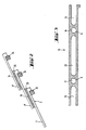
- the fragmentary roof shown in Fig. 1 has several, overlapping one another like a scale de roof covering elements 2, 2 'and 2 ", which rest on roof battens 24 which are fastened on rafters 23.
- the roof covering elements 2 and 2' are arranged in such a way that there is an overlap 3 for the roof 1.
- This overlap 3 forms one Gap 4 between the top of the roofing element 2 and the bottom of the roofing element 2 ', or between the top of the roofing element 2' and the bottom of the roofing element 2 ".
- Lines 17 and 18 of a line system 6 are arranged in this intermediate space 4.
- a heat pump not shown, extracts this heat from the cooling liquid and cools it down again.
- the heat energy extracted by the heat pump is brought to a higher temperature level and is then available as domestic heat for heating and hot water supply.
- the lines 17 and 18 of the line system 6 are embedded in grooves 8, which are formed in a bearing element 5.
- This bearing element 5 made of sheet metal is U-shaped with the two legs 9 and 10, and with the web 11, which can be designed as a bellows.
- the grooves 8 are formed in the two legs 9 and 10, in such a way that they each extend against the other leg 8.
- the lines 17 and 18 are located within these grooves.
- the legs 9 and 10 are in close contact with the underside or the top of the respective roofing elements 2 and 2 ', so that there is a very good contact surface and thus a very good heat transfer . Since the bearing element 5 is arranged in the intermediate space, it also serves as a seal within the intermediate space 4.
- the bearing element 5 is provided with at least one spacer 12, which can be designed, for example, as a steel spring or as a rubber element.
- This resilient spacer and the resilient web 11 make it possible to compensate for tolerances such as can occur due to the downward facing fold 13 and the rearward, upward facing fold 14 of the roofing element 2.
- the bearing element 5 can in this case be produced in advance in the form shown and provided with the lines, after which the entire arrangement is correspondingly arranged in the intermediate space when the roof is built up.
- the roof covering elements 2, 2 'and 2 " which are designed as bricks, can be provided with drip ribs 15 and 15' on the top and bottom sides. Furthermore, as shown in FIG. 1, the roof covering element 2 'rests on the bearing element 5, so that not only does a very good contact surface result, but also the tolerances due to the upward or downward folds 14 and 13. No further sealing is required in this case for flat bricks.
- the bearing element 5 has a height H, which determines the height of the space 4.
- the roofing elements can be in the form of bricks 2, 2 'and 2 ", these bricks being of a commercially available shape.
- the extruded aluminum profile 16 In front of, between and behind the lines 17 and 18 8, the extruded aluminum profile 16 has cavities 19, 20 and 21. 2, this extruded aluminum profile is introduced into the covering 3 between the respective roofing elements 2, 2 'and 2 ", ie the beaver tail tiles, which rest on the roof battens 24 in a manner known per se. Since the bearing element 16 has very good surface contact the beaver tail bricks, very good heat transfer is guaranteed.
- tiled roof elements which are known per se, the scale-like covering being such that an intermediate space is created into which a bearing element, for example shown in FIGS. 1 and 3, can be introduced, which is equipped with the lines of the line system.
- the bearing element can be formed in two pieces, and consist of a steel profile 30 and a flat sheet 31. At the edges and in the central area, the two parts 30 and 31 are tightly welded together.
- the steel profile 30 has two profile tracks 32 and 33, which are used for transporting and guiding the liquid medium.
- the profiled sheets 32 and 33 are closed on one side by end walls 34, the right profiled sheet 33 according to FIG. 5 being provided with a tube which serves as an end line 35. 4 can have a pipe opening 36, to which a drain pipe, not shown, can be connected.
- the construction of the bearing element with the steel profile 30 and the flat sheet metal part 31 creates a bearing element in a simple manner, which also already exists integrates the lines in the form of profile tracks 32 and 33.
- the troughs 41 and 42 of a trough brick 40 can be provided with labyrinth seals 43 in the form of webs 50 according to FIG in the front area of the brick.
- labyrinth seals result in a good sealing effect, so that the intermediate space 4 is perfectly protected from the weather.
- the bricks are provided with holding knobs on the upper side in the area of the intermediate space.
- the lines of the line system can rest against these retaining knobs and can be clamped in by the overlapping regions of the roofing elements, so that the lines of the line system can be easily held further.
- a roof with known tile roof shapes and other roof covering elements is used, the lines of the line system being able to be introduced into the intermediate space via a simply designed bearing element.
Landscapes
- Engineering & Computer Science (AREA)
- Chemical & Material Sciences (AREA)
- Physics & Mathematics (AREA)
- Life Sciences & Earth Sciences (AREA)
- Sustainable Development (AREA)
- Sustainable Energy (AREA)
- Thermal Sciences (AREA)
- Combustion & Propulsion (AREA)
- Mechanical Engineering (AREA)
- General Engineering & Computer Science (AREA)
- Dispersion Chemistry (AREA)
- Roof Covering Using Slabs Or Stiff Sheets (AREA)
Applications Claiming Priority (1)
| Application Number | Priority Date | Filing Date | Title |
|---|---|---|---|
| DE3014075A DE3014075C2 (de) | 1980-04-11 | 1980-04-11 | Dacheindeckung aus schuppenartig einander überlappenden Dacheindeckungsplatten |
Publications (2)
| Publication Number | Publication Date |
|---|---|
| EP0079882A1 EP0079882A1 (de) | 1983-06-01 |
| EP0079882B1 true EP0079882B1 (de) | 1985-09-25 |
Family
ID=6099828
Family Applications (1)
| Application Number | Title | Priority Date | Filing Date |
|---|---|---|---|
| EP81901526A Expired EP0079882B1 (de) | 1980-04-11 | 1981-05-27 | Dach mit schuppenartig sich überlappenden dachdekungselementen |
Country Status (7)
| Country | Link |
|---|---|
| EP (1) | EP0079882B1 (da) |
| AT (1) | AT386479B (da) |
| CH (1) | CH661084A5 (da) |
| DE (2) | DE3014075C2 (da) |
| DK (1) | DK522681A (da) |
| NL (1) | NL8120188A (da) |
| WO (1) | WO1982004305A1 (da) |
Families Citing this family (6)
| Publication number | Priority date | Publication date | Assignee | Title |
|---|---|---|---|---|
| WO1999014536A1 (de) * | 1997-09-18 | 1999-03-25 | Icec Ag | Sonnenkollektor |
| US6718703B2 (en) * | 2000-10-03 | 2004-04-13 | Lukley Holdings Pty Ltd. | Roofing tile assembly |
| WO2008128537A1 (en) * | 2007-04-18 | 2008-10-30 | Stobbe Tech A/S | An energy transmitting panel for invisible incorporation into a building and a cassette comprising such panel |
| AT505553B1 (de) * | 2007-08-02 | 2009-02-15 | Deutsch Wolfgang | Dachziegel |
| GB0812810D0 (en) * | 2008-07-12 | 2008-08-20 | Maskell Richard A M | Heat exchange plate for roofing applications |
| WO2010083988A2 (en) * | 2009-01-20 | 2010-07-29 | Cupa Innovacion, S.L.U. | An energy transmitting sheet profile for invisible incorporation into a building climate shield, and a method and sheet profile for such incorporation |
Citations (1)
| Publication number | Priority date | Publication date | Assignee | Title |
|---|---|---|---|---|
| DE7820719U1 (de) * | 1978-07-10 | 1978-10-12 | Assmann, Karl, Dipl.-Ing., 8000 Muenchen | Vorrichtung zur waermegewinnung aus der dachflaeche im nieder-temperatur-bereich (nt-dach-kollektor) |
Family Cites Families (8)
| Publication number | Priority date | Publication date | Assignee | Title |
|---|---|---|---|---|
| DE2336247A1 (de) * | 1973-07-17 | 1975-02-06 | Schoell Guenter | Sonnenkollektor |
| DE2702939C3 (de) * | 1977-01-25 | 1981-01-15 | Wohlwend, Gertraud, Triesenberg (Liechtenstein) | Dacheindeckung aus Blechtafeln |
| CH622339A5 (en) * | 1977-04-21 | 1981-03-31 | Concordia Dev Ab | Method for collecting solar energy for heating purposes as well as device for implementing the method |
| DE2722206A1 (de) * | 1977-05-17 | 1978-11-23 | Maschf Augsburg Nuernberg Ag | Solarflachkollektor |
| US4204520A (en) * | 1978-03-02 | 1980-05-27 | David Rosenberg | Roof comprising roofing tiles with solar water heating system therein |
| US4197834A (en) * | 1978-04-14 | 1980-04-15 | Nevins Robert L | Solar energy collector and associated methods adapted for use with overlapped roof shingles on the roof of a building |
| DE2853287A1 (de) * | 1978-12-09 | 1980-06-12 | Wolf Dipl Ing Hoffmann | Vorrichtung zur gewinnung nutzbarer waerme aus der natuerlichen und/oder kuenstlichen umwelt |
| NO802754L (no) * | 1979-10-09 | 1981-04-10 | Michael Christian Ludowici | Anordning for utnyttelse av omgivelsesenergi til oppvarming |
-
1980
- 1980-04-11 DE DE3014075A patent/DE3014075C2/de not_active Expired
- 1980-05-22 DE DE19803019639 patent/DE3019639A1/de not_active Withdrawn
-
1981
- 1981-05-27 EP EP81901526A patent/EP0079882B1/de not_active Expired
- 1981-05-27 WO PCT/DE1981/000077 patent/WO1982004305A1/de not_active Ceased
- 1981-05-27 CH CH519/83A patent/CH661084A5/de not_active IP Right Cessation
- 1981-05-27 AT AT0902781A patent/AT386479B/de active
- 1981-05-27 NL NL8120188A patent/NL8120188A/nl not_active Application Discontinuation
- 1981-11-25 DK DK522681A patent/DK522681A/da not_active Application Discontinuation
Patent Citations (1)
| Publication number | Priority date | Publication date | Assignee | Title |
|---|---|---|---|---|
| DE7820719U1 (de) * | 1978-07-10 | 1978-10-12 | Assmann, Karl, Dipl.-Ing., 8000 Muenchen | Vorrichtung zur waermegewinnung aus der dachflaeche im nieder-temperatur-bereich (nt-dach-kollektor) |
Also Published As
| Publication number | Publication date |
|---|---|
| ATA902781A (de) | 1988-01-15 |
| DK522681A (da) | 1982-12-09 |
| CH661084A5 (de) | 1987-06-30 |
| AT386479B (de) | 1988-08-25 |
| DE3019639A1 (de) | 1981-11-26 |
| WO1982004305A1 (fr) | 1982-12-09 |
| DE3014075A1 (de) | 1981-10-15 |
| NL8120188A (nl) | 1983-04-05 |
| DE3014075C2 (de) | 1984-06-07 |
| EP0079882A1 (de) | 1983-06-01 |
Similar Documents
| Publication | Publication Date | Title |
|---|---|---|
| DE3042952C2 (da) | ||
| EP0000543B1 (de) | Bausatz für Klimadächer oder Klimafassaden und seine Verwendung als Verdampfer | |
| DE2816970A1 (de) | Dach- oder wandteil mit waermeaustauscher | |
| DE3048499A1 (de) | Einrichtung zur umsetzung von sonnenenergie in waerme | |
| EP0006585A1 (de) | Solarabsorber | |
| CH661084A5 (de) | Dach mit sich schuppenartig ueberdeckend angeordneten dachdeckungselementen. | |
| DE2750602A1 (de) | Tafel zur ausnutzung der sonnenenergie | |
| DE2558612A1 (de) | Transparente kunststoffplatte | |
| EP0018543B1 (de) | Absorberelement zur Aufnahme von Solarenergie | |
| DE2702938A1 (de) | Waermeaustauschvorrichtung fuer gebaeude | |
| DE19745883C1 (de) | Sonnenkollektor | |
| DE2953533A1 (de) | Fassadenklappe fuer gebaeudefassaden | |
| DE2950045C2 (de) | Dacheindeckungsplatte mit Wärmeleitblech | |
| DE3205121C2 (de) | Heizungskessel | |
| DE2614145A1 (de) | Installationskanal, zur ableitung der aufgefangenen sonnenenergie | |
| DE19600579C1 (de) | Dachabdeckelement | |
| EP0045491A1 (de) | Raumheizgerät für Kleinräume | |
| DE102008050833A1 (de) | Klimatisierungssystem zur Anbringung auf einem Dach | |
| DE2633862A1 (de) | Sonnenkollektor | |
| DE19840544C5 (de) | Solarkollektorgehäuse | |
| DE2928482A1 (de) | Empfangs- und kollektorvorrichtung fuer sonnenenergie | |
| DE102006036000B3 (de) | Solarempfänger | |
| DE102010015851A1 (de) | Solarheizung | |
| DE20121297U1 (de) | Solarkollektor-Gehäuse | |
| DE2917098A1 (de) | Waermekollektor |
Legal Events
| Date | Code | Title | Description |
|---|---|---|---|
| PUAI | Public reference made under article 153(3) epc to a published international application that has entered the european phase |
Free format text: ORIGINAL CODE: 0009012 |
|
| 17P | Request for examination filed |
Effective date: 19820922 |
|
| AK | Designated contracting states |
Kind code of ref document: A1 Designated state(s): FR |
|
| RAP1 | Party data changed (applicant data changed or rights of an application transferred) |
Owner name: JOSEF MEINDL BETEILIGUNGS-OHG DORFEN |
|
| GRAA | (expected) grant |
Free format text: ORIGINAL CODE: 0009210 |
|
| AK | Designated contracting states |
Kind code of ref document: B1 Designated state(s): FR Designated state(s): FR |
|
| ET | Fr: translation filed | ||
| PLBE | No opposition filed within time limit |
Free format text: ORIGINAL CODE: 0009261 |
|
| STAA | Information on the status of an ep patent application or granted ep patent |
Free format text: STATUS: NO OPPOSITION FILED WITHIN TIME LIMIT |
|
| 26N | No opposition filed | ||
| PG25 | Lapsed in a contracting state [announced via postgrant information from national office to epo] |
Ref country code: FR Free format text: LAPSE BECAUSE OF NON-PAYMENT OF DUE FEES Effective date: 19870130 |
|
| REG | Reference to a national code |
Ref country code: FR Ref legal event code: ST |