EP0079930B1 - Systeme optique - Google Patents
Systeme optique Download PDFInfo
- Publication number
- EP0079930B1 EP0079930B1 EP82901817A EP82901817A EP0079930B1 EP 0079930 B1 EP0079930 B1 EP 0079930B1 EP 82901817 A EP82901817 A EP 82901817A EP 82901817 A EP82901817 A EP 82901817A EP 0079930 B1 EP0079930 B1 EP 0079930B1
- Authority
- EP
- European Patent Office
- Prior art keywords
- holographic
- screen
- pupil
- diffusing screen
- liquid crystal
- Prior art date
- Legal status (The legal status is an assumption and is not a legal conclusion. Google has not performed a legal analysis and makes no representation as to the accuracy of the status listed.)
- Expired
Links
- 230000003287 optical effect Effects 0.000 title claims abstract description 44
- 210000001747 pupil Anatomy 0.000 claims abstract description 44
- 238000005286 illumination Methods 0.000 claims abstract description 19
- 239000004973 liquid crystal related substance Substances 0.000 claims description 20
- 230000005540 biological transmission Effects 0.000 claims description 2
- 239000005337 ground glass Substances 0.000 abstract description 7
- 238000010586 diagram Methods 0.000 description 5
- 238000009792 diffusion process Methods 0.000 description 4
- 230000001427 coherent effect Effects 0.000 description 3
- 239000013598 vector Substances 0.000 description 3
- 238000010276 construction Methods 0.000 description 2
- 230000005855 radiation Effects 0.000 description 2
- 230000007423 decrease Effects 0.000 description 1
- 230000007812 deficiency Effects 0.000 description 1
- 230000001419 dependent effect Effects 0.000 description 1
- 238000007687 exposure technique Methods 0.000 description 1
- 230000002452 interceptive effect Effects 0.000 description 1
- 238000004519 manufacturing process Methods 0.000 description 1
- 238000000034 method Methods 0.000 description 1
- 238000012986 modification Methods 0.000 description 1
- 230000004048 modification Effects 0.000 description 1
- 238000002310 reflectometry Methods 0.000 description 1
- 230000035945 sensitivity Effects 0.000 description 1
- 239000000126 substance Substances 0.000 description 1
- 230000000007 visual effect Effects 0.000 description 1
Images


Classifications
-
- G—PHYSICS
- G02—OPTICS
- G02B—OPTICAL ELEMENTS, SYSTEMS OR APPARATUS
- G02B27/00—Optical systems or apparatus not provided for by any of the groups G02B1/00 - G02B26/00, G02B30/00
- G02B27/10—Beam splitting or combining systems
- G02B27/1086—Beam splitting or combining systems operating by diffraction only
- G02B27/1093—Beam splitting or combining systems operating by diffraction only for use with monochromatic radiation only, e.g. devices for splitting a single laser source
-
- G—PHYSICS
- G02—OPTICS
- G02B—OPTICAL ELEMENTS, SYSTEMS OR APPARATUS
- G02B5/00—Optical elements other than lenses
- G02B5/02—Diffusing elements; Afocal elements
- G02B5/0205—Diffusing elements; Afocal elements characterised by the diffusing properties
- G02B5/0252—Diffusing elements; Afocal elements characterised by the diffusing properties using holographic or diffractive means
-
- G—PHYSICS
- G02—OPTICS
- G02B—OPTICAL ELEMENTS, SYSTEMS OR APPARATUS
- G02B5/00—Optical elements other than lenses
- G02B5/32—Holograms used as optical elements
-
- G—PHYSICS
- G03—PHOTOGRAPHY; CINEMATOGRAPHY; ANALOGOUS TECHNIQUES USING WAVES OTHER THAN OPTICAL WAVES; ELECTROGRAPHY; HOLOGRAPHY
- G03H—HOLOGRAPHIC PROCESSES OR APPARATUS
- G03H1/00—Holographic processes or apparatus using light, infrared or ultraviolet waves for obtaining holograms or for obtaining an image from them; Details peculiar thereto
- G03H1/04—Processes or apparatus for producing holograms
- G03H1/0402—Recording geometries or arrangements
- G03H2001/0428—Image holography, i.e. an image of the object or holobject is recorded
-
- G—PHYSICS
- G03—PHOTOGRAPHY; CINEMATOGRAPHY; ANALOGOUS TECHNIQUES USING WAVES OTHER THAN OPTICAL WAVES; ELECTROGRAPHY; HOLOGRAPHY
- G03H—HOLOGRAPHIC PROCESSES OR APPARATUS
- G03H1/00—Holographic processes or apparatus using light, infrared or ultraviolet waves for obtaining holograms or for obtaining an image from them; Details peculiar thereto
- G03H1/04—Processes or apparatus for producing holograms
- G03H1/0402—Recording geometries or arrangements
- G03H2001/0439—Recording geometries or arrangements for recording Holographic Optical Element [HOE]
-
- G—PHYSICS
- G03—PHOTOGRAPHY; CINEMATOGRAPHY; ANALOGOUS TECHNIQUES USING WAVES OTHER THAN OPTICAL WAVES; ELECTROGRAPHY; HOLOGRAPHY
- G03H—HOLOGRAPHIC PROCESSES OR APPARATUS
- G03H1/00—Holographic processes or apparatus using light, infrared or ultraviolet waves for obtaining holograms or for obtaining an image from them; Details peculiar thereto
- G03H1/22—Processes or apparatus for obtaining an optical image from holograms
- G03H1/2249—Holobject properties
- G03H2001/2284—Superimposing the holobject with other visual information
Definitions
- This invention is directed to an optical system comprising:
- Such an optical system which forms a head-up display is disclosed in US-A-3 915 548.
- the performance of such a display for viewing by an observer is limited by the brightness and resolui tion of the image as perceived by a person in the viewing zone.
- the brightness of the image in a particular portion of a screen varies with the viewer's position.
- the screen is not at the same brightness over the whole area, and the distribution of the light is dependent upon the viewer's position within the viewing zone.
- This type of distribution of light on the screen makes it difficult for the viewer to observe all parts of the viewing screen and extract information thdrefrom with reliability. Therefore, in many cases a screen of uniform brightness is desirable. In other cases a selected variation of brightness over the viewing area or pupil may be desired.
- a display screen which is made by holographic exposure techniques which provide a diffusing screen of uniquely different characteristics as compared to a conventional ground glass diffusing screen.
- the directional diffusing screen so constructed is in essence a hologram that reconstructs a real image of a diffuse disc when illuminated by the appropriate reference beam. The parts of the hologram which are illuminated by the reference beam will themselves appear bright when viewed from the viewing pupil.
- a holographic directional diffusing screen is positioned at the second image focal plane for diffracting a substantial portion of the incoming substantially monochromatic light via the holographic optical element combiner to a viewing pupil by means of which a ray of light incident on any particular point on said holographic directional diffusing screen from the lens means is redirected and diffused into a predetermined directional range intercepting a designated pupil region in space, whereby the light diffracted from said incident beam by said holographic directional diffusing screen is substantially directed within and illuminates said pupil region with selected intensity distribution so that the information at said information carrying liquid crystal screen is viewable at said viewing pupil as diffused information with substantially uniform illumination across said pupil.
- a special advantage of this optical system consists in that it allows to select the output pupil position which defines the viewing zone independently of the input illumination angle and to direct substantially all of the illumination energy to the viewing pupil so that the entire diffusion screen is selectively illuminated.
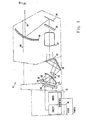
- the display system 10 illustrated in FIG. 1, is a system by which a real image and a data display image can be combined for simultaneous seeing by a viewer. This is accomplished by providing an electronic system 12 which receives data through data line 14 to drive liquid crystal display 16. The information on the surface of liquid crystal display 16 can be viewed by reflected light.
- Lamp 18 with its reflector 20 projects substantially monochromatic light through filter 22 onto reflecting mirror 24 which delivers light to the liquid crystal display 16 by which the liquid crystal display is illuminated.
- the liquid crystal display is of such nature that data thereon occurs as different reflectivity so that the data may be visually observed.
- the illumination of liquid crystal display 16 is projected through viewing port 26 and through a projection lens 28.
- Mirror 30 folds the optical path and the light is delivered to the directional diffusing screen 32 of this invention at the focal plane.
- Light from diffusing screen 32 is delivered through relay optics 34 and through filter 36 to mirror 38.
- Mirror 38 delivers the energy to holographic optical element combiner 40.
- Viewer 42 sees a first set of information along optical path 44 in which the diffuse image of information on liquid crystal display 16 is seen.
- 'he sees a second set of information along the second optical path 46 which may be a view of the real world. Since the holographic optical element combiner 40 reflects only in the specified wavelength, it is virtually transparent to optical information along the second path 46, which presumably is on a broad spectrum, for example a real world view. Viewer 42 thus sees the information displayed on liquid crystal display 16 as superimposed upon real world information.
- Directional diffusing screen 32 which is a holographic optical element, has properties which provide illumination of selected intensity distribution such as uniform into a pupil.
- the pupil is the entrance pupil to relay optics 34.
- FIG. 2 illustrates the function of the directional diffusing screen 32 of this invention.
- Light is projected through aperture 47 by lens 49 from focal plane 48 onto directional diffusing screen 32.
- the projection from the focal plane 48 through lens 49 includes a central ray 50, which need not be normal to the plane of directional diffusing screen 32.
- Directional diffusing screen 32 has two properties. First it diffuses substantially all of the incoming energy into a predetermined viewing pupil 52 which is illustrated as being of circular configuration and has a selected pupil diameter.
- the central ray 54 from directional diffusing screen 32 to the center of pupil 52 also need not be normal to the surface of directional diffusing screen 32. In the illustration shown in FIG. 2, neither of the central rays 50 or 54 are normal to screen 32, and they are not parallel or coincident to each other. This is one of the properties of directional diffusing screen 32.
- the other property is that substantially all of the energy from the directional diffusing screen appears at pupil 52.
- FIGS. 3 and 4 illustrate these features with more particularity.
- Diffusing screen 56 is a prior art structure, such as ground glass.
- Incoming ray 58 is diffused into an energy envelope 60 which is of a typical shape similar to a tear drop or an ellipse depending on the characteristics of screen 56.
- the shape of the energy envelope 60 represents the tips of the illumination vectors.
- the intensity is less.
- illumination intensity decreases as is indicated by the shape of envelope 60.
- the dashed lines in FIG. 3 illustrate the intensity distribution if the diffused energy was restricted to a cone.
- the directional diffusing screen 32 of this invention is shown in FIG. 4.
- Incoming ray 66 is diffused by screen 32 into a conical envelope 68 with a ' viewing or output pupil 70.
- the envelope 68 is structured in the same way as envelope 60, in that each of the vectors in the envelope represents the direction of illumination and intensity of illumination in that direction.
- Each of the vectors directed toward the pupil 70 is of the same length, so that when viewed anywhere in the pupil 70, the light intensity remains the same. Uniform intensity across the pupil is selected as preferred in the present illustrative use.
- the holographic optical element diffusing screen can be configured to give a different energy distribution, if desired.
- the directional diffusing screen 32 has the property that little energy is dissipated outside of the envelope 68.
- the central ray 72 in the envelope need not be parallel to or coincident with incoming ray 66. Neither the incoming ray nor the central ray 72 need be normal to the directional diffusing screen 32. If desired, either or both may be normal to that su rface.
- FIGS. 5 and 6 illustrate the manner in which the directional diffusing screen 32, can be made.
- point sources of focused coherent monochromatic light are shown at 74 and 76. Preferably they are the same source, suitably optically connected.
- Holographic sensitive plate 78 is to be exposed and developed to become the directional diffusing screen 32.
- Holographic sensitive plate 78 can be any conventional holographic recording medium and technique. A particular example is described in more detail in U.S.-A-4 318 970, filed April 4, 1980 by I. J. Kurland et al. In that patent application, the chemical character of the plate, its exposure and exposure sensitivity and its development are described in detail. The disclosure of that patent is incorporated herein in its entirety by this reference.
- Point source 74 illuminates plate 78 and represents the direction of incoming light from the source which will later illuminate the developed directional diffusing screen 32.
- the central ray 90 from point source 74 to the plate 78 represents the central ray 50 to the screen 32 in FIG. 2.
- Point source 76 illuminates diffusing screen 80 which is of ordinary characteristics. For example, it may be of ground glass.
- the image of the illuminated diffusing screen 80 is focused by mirror 82 toward an image plane 84, which represents the output pupil 52 of FIG. 2.
- image plane 84 which represents the output pupil 52 of FIG. 2.
- mirror 80 images point source 76 at the region of plate 78.
- the central ray 86 from the center of diffusing screen 80 reflects on projection mirror 82.
- the reflected central ray 88 impinges on the center of hologram sensitive plate 78 and is directed toward image plane 84 which corresponds to the later viewing pupil (or entrance pupil of relay optics).
- the central ray 90 from point source 74 is also illustrated.
- the illumination from diffusing screen 80 and from point source 74 cause the production of a latent image on holographic sensitive plate 78. This plate is then developed to become directional diffusing screen 32. When the directional diffusing screen 32 is illuminated from a monochromatic source, then at pupil 52 is seen an image of the ground glass diffusing screen 80. Due to the uniform illumination of diffusing screen 80 in the preferred embodiment, illumination is uniform across the pupil 52.
- the schematic exposure assembly illustrated in . FIG. 6 is quite similar.
- point source 74 of coherent monochromatic light illuminates holographic sensitive plate 78.
- point source 76 of monochromatic coherent light illuminates diffusing screen 80.
- the two point sources are of related coherence or are preferably the same source, optically connected.
- lens 92 focuses the image of diffusing screen 80 through sensitive plate 78 to image plane 94.
- the interference of the wavefronts passing through the sensitive plate 78 creates a latent image therein which is then developed to provide the directional diffusing screen 32.
- the image of the ground glass is seen at the image plane or pupil 94. It is apparent from Figs. 5 and 6 that the large lens 92 is difficult to provide and the mirror 82 is the optical equivalent thereof.
- screen 32 is a transmission holographic optical elements.
- a reflection holographic optical element can be produced to have similar characteristics.
- Directional diffusing screen 32 is of such nature that it presents a predefined pupil through which is seen the image of a diffusing screen, and the angle of entrance illumination may be different than the central ray to the pupil.
- FIG. 7 illustrates holographic optical element 96 which is in the form of a directional screen and holographic optical element 98 which is in the form of the image of a diffusing screen.
- the two holdgraphic optical elements 96 and 98 then separately have the directional screen function and the diffusing screen function. Elements 96 and 98 lie closely together. These functions are combined in the directional diffusing screen holographic optical element 32.
- the illuminated focal plane 100 which may be a visual information source, is focused onto directional screen 98. Its central ray is indicated at 102.
- Directional screen holographic optical element 96 is formed so that the incoming illumination is redirected so that central ray 104 is at an angle to central ray 102.
- the redirected image information from directional screen 96 is directed onto holographic element diffusion screen 98 which diffuses the optical information into a ray pattern which uniformly illuminates pupil 106, similar to pupil 52.
- the directional function and the diffusion function can be separated in separate holographic optical elements adjacent to each other.
Landscapes
- Physics & Mathematics (AREA)
- General Physics & Mathematics (AREA)
- Optics & Photonics (AREA)
- Diffracting Gratings Or Hologram Optical Elements (AREA)
- Holo Graphy (AREA)
- Overhead Projectors And Projection Screens (AREA)
- Optical Elements Other Than Lenses (AREA)
Claims (3)
Applications Claiming Priority (2)
| Application Number | Priority Date | Filing Date | Title |
|---|---|---|---|
| US06/270,159 US4372639A (en) | 1981-06-03 | 1981-06-03 | Directional diffusing screen |
| US270159 | 1999-03-16 |
Publications (3)
| Publication Number | Publication Date |
|---|---|
| EP0079930A1 EP0079930A1 (fr) | 1983-06-01 |
| EP0079930A4 EP0079930A4 (fr) | 1983-10-04 |
| EP0079930B1 true EP0079930B1 (fr) | 1986-03-12 |
Family
ID=23030154
Family Applications (1)
| Application Number | Title | Priority Date | Filing Date |
|---|---|---|---|
| EP82901817A Expired EP0079930B1 (fr) | 1981-06-03 | 1982-05-03 | Systeme optique |
Country Status (6)
| Country | Link |
|---|---|
| US (1) | US4372639A (fr) |
| EP (1) | EP0079930B1 (fr) |
| JP (1) | JPS58500875A (fr) |
| DE (1) | DE3269782D1 (fr) |
| IL (1) | IL65476A (fr) |
| WO (1) | WO1982004327A1 (fr) |
Families Citing this family (69)
| Publication number | Priority date | Publication date | Assignee | Title |
|---|---|---|---|---|
| US4500163A (en) * | 1981-07-29 | 1985-02-19 | The Singer Company | Holographic projection screen |
| US4613200A (en) * | 1984-07-09 | 1986-09-23 | Ford Motor Company | Heads-up display system with holographic dispersion correcting |
| US4610499A (en) * | 1984-11-01 | 1986-09-09 | The United States Of America As Represented By The Secretary Of The Air Force | Diffraction diffusion screen with holographically suppressed zero-order beam |
| JPH0623817B2 (ja) * | 1985-07-18 | 1994-03-30 | 旭光学工業株式会社 | 液晶投写型画像表示装置 |
| US4799765A (en) * | 1986-03-31 | 1989-01-24 | Hughes Aircraft Company | Integrated head-up and panel display unit |
| US4976536A (en) * | 1987-04-30 | 1990-12-11 | Nview Corporation | Liquid crystal display for projection systems |
| US5187510A (en) * | 1987-04-30 | 1993-02-16 | Nview Corporation | Liquid crystal display for projection systems |
| US5255029A (en) * | 1987-04-30 | 1993-10-19 | Nview Corporation | Liquid crystal display for projection systems |
| US4763993A (en) * | 1987-04-30 | 1988-08-16 | N-View Corporation | Liquid crystal display for projection systems |
| US5227821A (en) * | 1987-04-30 | 1993-07-13 | Nview Corporation | Liquid crystal display for projection systems |
| FR2614998B1 (fr) * | 1987-05-07 | 1989-12-29 | Thomson Csf | Dispositif optique holographique constituant un diffuseur et procede d'obtention |
| US4807978A (en) * | 1987-09-10 | 1989-02-28 | Hughes Aircraft Company | Color display device and method using holographic lenses |
| US5278532A (en) * | 1987-09-14 | 1994-01-11 | Hughes Aircraft Company | Automotive instrument virtual image display |
| GB2222000A (en) * | 1988-06-22 | 1990-02-21 | Dimplex Ltd Glen | Optical component used for flame effect in heating apparatus |
| US5016950A (en) * | 1988-07-05 | 1991-05-21 | Hughes Aircraft Company | Full-color zero-order suppressed diffraction optics diffusing screen/louver filter laminate |
| US4960314A (en) * | 1988-07-05 | 1990-10-02 | Hughes Aircraft Company | Diffraction optics diffusing screen laminate for full color on-axis viewing |
| US4896929A (en) * | 1988-07-15 | 1990-01-30 | Xerox Corporation | Holographic display module for displaying machine status |
| US4944578A (en) * | 1988-07-21 | 1990-07-31 | Telex Communications | Color graphic imager utilizing a liquid crystal display |
| US5044709A (en) * | 1988-11-30 | 1991-09-03 | Hughes Aircraft Company | LED array polarized image source/0 degree hologram virtual image head up display |
| US5011244A (en) * | 1988-12-16 | 1991-04-30 | Hughes Aircraft Company | Holographic full color data retrieval and projection system |
| US5046793A (en) * | 1989-05-26 | 1991-09-10 | Litton Systems, Inc. | Chromatically corrected directional diffusing screen |
| GB8924831D0 (en) * | 1989-11-03 | 1990-04-25 | Marconi Gec Ltd | Helmet mounted display |
| US5103325A (en) * | 1990-10-01 | 1992-04-07 | Xerox Corporation | Segmented hologram for multi-image display |
| EP0479490A3 (en) * | 1990-10-02 | 1992-08-12 | Physical Optics Corporation | Volume holographic diffuser |
| US5257094A (en) * | 1991-07-30 | 1993-10-26 | Larussa Joseph | Helmet mounted display system |
| US5291316A (en) * | 1991-09-27 | 1994-03-01 | Astronautics Corporation Of America | Information display system having transparent holographic optical element |
| DE4234191C2 (de) * | 1992-10-10 | 1995-09-28 | Hoerdum Martin | Anzeigevorrichtung für Informationsdarstellung mittels Hologramm |
| US5757544A (en) * | 1993-03-09 | 1998-05-26 | Olympus Optical Co., Ltd. | Image display apparatus |
| US5471327A (en) * | 1993-05-14 | 1995-11-28 | Kaiser Optical Systems, Inc. | Holographic diffuser for back-lit display |
| US5418631A (en) * | 1993-05-14 | 1995-05-23 | Kaiser Optical Systems, Inc. | Edge-lit holographic diffusers for flat-panel displays |
| EP0714348A4 (fr) * | 1993-07-27 | 1998-05-06 | Physical Optics Corp | Dispositif de destructuration et de mise en forme d'une source de lumiere |
| FR2716983B1 (fr) * | 1994-03-03 | 1996-05-24 | Hologram Ind Sarl | Procédé pour réaliser une image optiquement variable. |
| JPH07253621A (ja) * | 1994-03-16 | 1995-10-03 | Fujitsu Ltd | スクリーン及びこれを用いた投写型表示装置 |
| GB9411561D0 (en) * | 1994-06-07 | 1994-08-03 | Richmond Holographic Res | Stereoscopic display |
| US6123877A (en) * | 1994-12-28 | 2000-09-26 | Nashua Corporation | Asymmetric light diffusing material |
| EP0726681B1 (fr) * | 1995-02-10 | 2003-04-23 | Sharp Kabushiki Kaisha | Appareil d'affichage d'image par projection |
| US5659408A (en) * | 1995-05-24 | 1997-08-19 | Polaroid Corporation | Reflective image-providing display viewed with holographically diffused ambient light |
| EP0772103A3 (fr) * | 1995-10-30 | 1998-01-21 | Denso Corporation | Procédé pour la réalisation d'un hologramme et dispositif d'affichage l'utilisant |
| JP3700948B2 (ja) * | 1995-11-30 | 2005-09-28 | 大日本印刷株式会社 | ホログラムを用いた液晶ディスプレイ装置 |
| JPH10133283A (ja) * | 1996-09-05 | 1998-05-22 | Denso Corp | 透過型ホログラムスクリーンの製造方法 |
| US5890796A (en) * | 1997-01-16 | 1999-04-06 | Ford Global Technologies, Inc. | Laser illuminated lighting system utilizing a diffractive optical element |
| US5796499A (en) * | 1997-02-28 | 1998-08-18 | Polaroid Corporation | Transmission holographic diffuser made and used to effect lateral color constancy in rear screen projection display systems |
| US5999281A (en) * | 1997-02-28 | 1999-12-07 | Polaroid Corporation | Holographic projection screen combining an elliptical holographic diffuser and a cylindrical light-collimator |
| DE19730563A1 (de) * | 1997-07-17 | 1999-02-11 | Daimler Benz Ag | Verwendung eines holographischen Bildschirmes als Darstellungsfläche in einem Fahrzeug |
| US6288803B1 (en) | 1997-10-27 | 2001-09-11 | Denso Corporation | Hologram display |
| JP4081838B2 (ja) * | 1997-12-26 | 2008-04-30 | ノーリツ鋼機株式会社 | 特定視点画像表示装置及び多視点画像表示装置 |
| US6036340A (en) * | 1998-03-03 | 2000-03-14 | Ford Global Technologies, Inc. | Dimpled manifold optical element for a vehicle lighting system |
| EP0971247A1 (fr) * | 1998-07-07 | 2000-01-12 | Denso Corporation | Ecran holographique et méthode de sa fabrication |
| US6175431B1 (en) | 1999-07-09 | 2001-01-16 | Digilens, Inc. | Projection systems based on reconfigurable holographic optics |
| AU5231699A (en) * | 1998-07-29 | 2000-02-21 | Digilens Inc. | Projection screen based on reconfigurable holographic optics for implementation in head-mounted displays |
| US6082862A (en) * | 1998-10-16 | 2000-07-04 | Digilens, Inc. | Image tiling technique based on electrically switchable holograms |
| US6191876B1 (en) * | 1998-10-16 | 2001-02-20 | Digilens, Inc. | Light diffusion control by electrically reconfigurable holographic optical elements |
| US6040928A (en) * | 1998-11-16 | 2000-03-21 | Digilens, Inc. | Holographic desktop monitor |
| US6301027B1 (en) | 1998-11-16 | 2001-10-09 | Digilens, Inc. | Holographic desktop monitor |
| EP1006375A1 (fr) * | 1998-12-02 | 2000-06-07 | HSM Holographic Systems München GmbH | Système holographique d'affichage d'information comportant un écran holographique d'image intermédiaire et méthode de production dudit écran holographique |
| IL157838A (en) * | 2003-09-10 | 2013-05-30 | Yaakov Amitai | High-brightness optical device |
| US7069685B2 (en) * | 2003-09-12 | 2006-07-04 | Lasermax, Inc. | Diffractive head up display for firearms |
| US10073264B2 (en) | 2007-08-03 | 2018-09-11 | Lumus Ltd. | Substrate-guide optical device |
| US8004759B2 (en) * | 2009-02-02 | 2011-08-23 | Microsoft Corporation | Diffusing screen |
| US20110032587A1 (en) * | 2009-03-20 | 2011-02-10 | Absolute Imaging LLC | System and Method for Autostereoscopic Imaging |
| IL232197B (en) | 2014-04-23 | 2018-04-30 | Lumus Ltd | Compact head-up display system |
| JP7187022B2 (ja) | 2016-10-09 | 2022-12-12 | ルムス エルティーディー. | 長方形導波路を使用する開口乗算器 |
| KR102541662B1 (ko) | 2016-11-08 | 2023-06-13 | 루머스 리미티드 | 광학 컷오프 에지를 구비한 도광 장치 및 그 제조 방법 |
| WO2019016813A1 (fr) | 2017-07-19 | 2019-01-24 | Lumus Ltd. | Éclairage à cristaux liquides sur silicium par l'intermédiaire d'un élément optique guide de lumière |
| IL259518B2 (en) | 2018-05-22 | 2023-04-01 | Lumus Ltd | Optical system and method for improving light field uniformity |
| US11415812B2 (en) | 2018-06-26 | 2022-08-16 | Lumus Ltd. | Compact collimating optical device and system |
| KR102651647B1 (ko) | 2019-03-12 | 2024-03-26 | 루머스 리미티드 | 이미지 프로젝터 |
| KR20250172729A (ko) | 2019-09-16 | 2025-12-09 | 루머스 리미티드 | 헤드 마운트 디스플레이용 컴팩트 프로젝터 |
| JP7497079B2 (ja) | 2019-12-08 | 2024-06-10 | ルーマス リミテッド | コンパクト画像プロジェクタを備える光学系 |
Family Cites Families (7)
| Publication number | Priority date | Publication date | Assignee | Title |
|---|---|---|---|---|
| DE1918375A1 (de) * | 1969-04-11 | 1970-10-15 | Agfa Gevaert Ag | Anordnung zur Herstellung eines Lichtwellenfeldes |
| US3708217A (en) * | 1971-04-28 | 1973-01-02 | Sperry Rand Corp | Holographic non-isotropic diffusing screen |
| US3915548A (en) * | 1973-04-30 | 1975-10-28 | Hughes Aircraft Co | Holographic lens and liquid crystal image source for head-up display |
| US3909111A (en) * | 1974-02-27 | 1975-09-30 | Rca Corp | Controlled angle viewing screens by interference techniques |
| US3901578A (en) * | 1974-03-18 | 1975-08-26 | Rca Corp | Illuminator employing holographic technique |
| GB1579214A (en) * | 1978-05-26 | 1980-11-12 | Central Electr Generat Board | Screens for optical imaging systems |
| US4218111A (en) * | 1978-07-10 | 1980-08-19 | Hughes Aircraft Company | Holographic head-up displays |
-
1981
- 1981-06-03 US US06/270,159 patent/US4372639A/en not_active Expired - Lifetime
-
1982
- 1982-04-12 IL IL65476A patent/IL65476A/xx not_active IP Right Cessation
- 1982-05-03 WO PCT/US1982/000585 patent/WO1982004327A1/fr not_active Ceased
- 1982-05-03 EP EP82901817A patent/EP0079930B1/fr not_active Expired
- 1982-05-03 DE DE8282901817T patent/DE3269782D1/de not_active Expired
- 1982-05-03 JP JP57501843A patent/JPS58500875A/ja active Pending
Also Published As
| Publication number | Publication date |
|---|---|
| EP0079930A1 (fr) | 1983-06-01 |
| US4372639A (en) | 1983-02-08 |
| JPS58500875A (ja) | 1983-05-26 |
| IL65476A (en) | 1985-11-29 |
| IL65476A0 (en) | 1982-07-30 |
| EP0079930A4 (fr) | 1983-10-04 |
| DE3269782D1 (en) | 1986-04-17 |
| WO1982004327A1 (fr) | 1982-12-09 |
Similar Documents
| Publication | Publication Date | Title |
|---|---|---|
| US4372639A (en) | Directional diffusing screen | |
| US4586780A (en) | Directional diffusing screen with suppressed zero-order light | |
| US4799765A (en) | Integrated head-up and panel display unit | |
| US4586781A (en) | Diffraction optics diffusing screen | |
| US6542265B2 (en) | Method for producing a hologram and a display device using the same | |
| US5600454A (en) | Viewing apparatus | |
| AU590835B2 (en) | Integrated head-up and panel display unit | |
| EP0605652A1 (fr) | Systeme d'affichage d'informations a element optique holographique transparent | |
| US5499116A (en) | Encoded hologram for producing a machine readable image and a human readable image | |
| US4598973A (en) | Apparatus and method for recording and displaying a three-dimensional image | |
| US6643039B1 (en) | Holographic reflector and reflectiver liquid crystal display using it | |
| US6211977B1 (en) | Method of producing a holographic projection screen for displaying a three-dimensional color images | |
| JPH0928530A (ja) | ホログラムを用いた情報表示展示装置 | |
| Pawluczyk | Holographic diffusers | |
| JP3346296B2 (ja) | ホログラムスクリーンの製造方法 | |
| WO2022113614A1 (fr) | Dispositif d'affichage | |
| JPH0311422B2 (fr) | ||
| JP3580920B2 (ja) | ホログラムの作製方法 | |
| JPH11258427A (ja) | ホログラム反射板とそれを用いた反射型液晶表示装置 | |
| JPH09127612A (ja) | ホログラムの作製方法 | |
| JPH11316538A (ja) | ホログラムの作製方法 | |
| JPH09258642A (ja) | ホログラムの製造方法および露光装置 |
Legal Events
| Date | Code | Title | Description |
|---|---|---|---|
| PUAI | Public reference made under article 153(3) epc to a published international application that has entered the european phase |
Free format text: ORIGINAL CODE: 0009012 |
|
| AK | Designated contracting states |
Designated state(s): DE GB SE |
|
| 17P | Request for examination filed |
Effective date: 19830528 |
|
| RAP1 | Party data changed (applicant data changed or rights of an application transferred) |
Owner name: HUGHES AIRCRAFT COMPANY |
|
| GRAA | (expected) grant |
Free format text: ORIGINAL CODE: 0009210 |
|
| AK | Designated contracting states |
Kind code of ref document: B1 Designated state(s): DE GB SE |
|
| REF | Corresponds to: |
Ref document number: 3269782 Country of ref document: DE Date of ref document: 19860417 |
|
| PLBE | No opposition filed within time limit |
Free format text: ORIGINAL CODE: 0009261 |
|
| STAA | Information on the status of an ep patent application or granted ep patent |
Free format text: STATUS: NO OPPOSITION FILED WITHIN TIME LIMIT |
|
| 26N | No opposition filed | ||
| EAL | Se: european patent in force in sweden |
Ref document number: 82901817.5 |
|
| REG | Reference to a national code |
Ref country code: GB Ref legal event code: 732E |
|
| PGFP | Annual fee paid to national office [announced via postgrant information from national office to epo] |
Ref country code: DE Payment date: 20010430 Year of fee payment: 20 |
|
| PGFP | Annual fee paid to national office [announced via postgrant information from national office to epo] |
Ref country code: GB Payment date: 20010502 Year of fee payment: 20 |
|
| PGFP | Annual fee paid to national office [announced via postgrant information from national office to epo] |
Ref country code: SE Payment date: 20010504 Year of fee payment: 20 |
|
| REG | Reference to a national code |
Ref country code: GB Ref legal event code: IF02 |
|
| PG25 | Lapsed in a contracting state [announced via postgrant information from national office to epo] |
Ref country code: GB Free format text: LAPSE BECAUSE OF EXPIRATION OF PROTECTION Effective date: 20020502 |
|
| REG | Reference to a national code |
Ref country code: GB Ref legal event code: 732E |
|
| REG | Reference to a national code |
Ref country code: GB Ref legal event code: PE20 Effective date: 20020502 |
|
| EUG | Se: european patent has lapsed |
Ref document number: 82901817.5 |