EP0079977B1 - Pièce de contact pour interrupteur électrique, en particulier pour interrupteur de protection - Google Patents
Pièce de contact pour interrupteur électrique, en particulier pour interrupteur de protection Download PDFInfo
- Publication number
- EP0079977B1 EP0079977B1 EP81109823A EP81109823A EP0079977B1 EP 0079977 B1 EP0079977 B1 EP 0079977B1 EP 81109823 A EP81109823 A EP 81109823A EP 81109823 A EP81109823 A EP 81109823A EP 0079977 B1 EP0079977 B1 EP 0079977B1
- Authority
- EP
- European Patent Office
- Prior art keywords
- contact
- supporting member
- arc
- arc conducting
- intermediate part
- Prior art date
- Legal status (The legal status is an assumption and is not a legal conclusion. Google has not performed a legal analysis and makes no representation as to the accuracy of the status listed.)
- Expired
Links
- 239000003302 ferromagnetic material Substances 0.000 claims abstract description 6
- 239000004020 conductor Substances 0.000 claims abstract description 5
- 239000000463 material Substances 0.000 claims abstract description 5
- 229910000831 Steel Inorganic materials 0.000 abstract description 5
- 239000010959 steel Substances 0.000 abstract description 5
- 230000006378 damage Effects 0.000 abstract description 4
- RYGMFSIKBFXOCR-UHFFFAOYSA-N Copper Chemical compound [Cu] RYGMFSIKBFXOCR-UHFFFAOYSA-N 0.000 abstract description 2
- 229910052802 copper Inorganic materials 0.000 abstract description 2
- 239000010949 copper Substances 0.000 abstract description 2
- 229910000881 Cu alloy Inorganic materials 0.000 abstract 1
- 230000003628 erosive effect Effects 0.000 description 5
- 238000005219 brazing Methods 0.000 description 3
- 239000011324 bead Substances 0.000 description 2
- 230000015572 biosynthetic process Effects 0.000 description 1
- 238000010276 construction Methods 0.000 description 1
- 230000000694 effects Effects 0.000 description 1
- 238000004519 manufacturing process Methods 0.000 description 1
- 230000005012 migration Effects 0.000 description 1
- 238000013508 migration Methods 0.000 description 1
- 230000007704 transition Effects 0.000 description 1
Images
Classifications
-
- H—ELECTRICITY
- H01—ELECTRIC ELEMENTS
- H01H—ELECTRIC SWITCHES; RELAYS; SELECTORS; EMERGENCY PROTECTIVE DEVICES
- H01H9/00—Details of switching devices, not covered by groups H01H1/00 - H01H7/00
- H01H9/30—Means for extinguishing or preventing arc between current-carrying parts
- H01H9/46—Means for extinguishing or preventing arc between current-carrying parts using arcing horns
-
- H—ELECTRICITY
- H01—ELECTRIC ELEMENTS
- H01H—ELECTRIC SWITCHES; RELAYS; SELECTORS; EMERGENCY PROTECTIVE DEVICES
- H01H1/00—Contacts
- H01H1/12—Contacts characterised by the manner in which co-operating contacts engage
- H01H1/14—Contacts characterised by the manner in which co-operating contacts engage by abutting
- H01H1/20—Bridging contacts
Definitions
- the present invention relates to a contact piece, preferably a contact bridge, for an electrical switching device, in particular for a contactor, according to the preamble of claim 1.
- a contact bridge with a trough-shaped carrier is known, to which an intermediate part made of electrically conductive material is attached. Two contact pads are soldered onto this intermediate part.
- the intermediate part has end parts which extend away from the contact pads and adjoin the end faces of the carrier. These end parts serve as arcing pieces.
- a contact bridge in which the contact pads are attached directly to the bottom part of a U-shaped support and are connected to one another in an electrically conductive manner by means of a web (DE-AS 1 175776).
- Arc guide pieces are attached to the end faces of the carrier and protrude from the base part of the carrier in the direction away from the contact pads. Since these arc guide pieces are made of steel, the arc base points move away from the contact pads more quickly than in the case of the contact bridge mentioned above.
- the connection point between the contact pads and the carrier is attacked by the arcs, which migrate with their base points along the side of the contact pads to the arc guide pieces. The damage caused as a result, which is particularly significant with high switch-off currents, makes it necessary to replace the contact bridge after a relatively short period of use.
- a contact bridge which has a contact bridge support with two contact pads attached to it at a mutual distance. These contact pads are connected to one another in an electrically conductive manner via the contact bridge carrier.
- This contact bridge support is provided with beads which lie laterally on the contact supports and extend against the contact surface of the contact supports and end at a distance from these contact surfaces. These beads are formed in one piece with the contact bridge support and therefore, like this, consist of an electrically conductive material.
- the object of the present invention is to create a contact piece of the type mentioned at the beginning which is simple in construction and manufacture and which, with the smallest possible mass, permits high switching numbers even with large breaking currents.
- the arc guide piece extends to the height of the contact surface of the associated contact support, this contact surface and the end of the arc guide piece lie approximately in one plane, which is a prerequisite for the fastest possible passage of the arc base points onto the arc guide piece.
- This rapid commutation of the arc foot arcs from the contact pad to the arc guide is effectively supported by the fact that the arc guide is made of ferromagnetic material and comes very close to the contact surface.
- the arc guide made of ferromagnetic material is also resistant to erosion and has good arc running properties, so that the arcs are quickly guided away from the contact pad. Since the arc base points quickly move away from the contact surface, the erosion of the contact pads is reduced to a minimum. Accordingly, the wear of the contact piece according to the invention is low even with relatively large breaking currents, which enables the contact piece to be used for a correspondingly long time.
- the carrier can be made of a material of high mechanical strength, so that the intermediate part essentially only has to ensure a good electrically conductive connection between the contact pads. This makes it possible to create a contact piece that is as small as possible and that can withstand strong electrical and mechanical stresses both when the contacts are closed and when the contacts are opened and closed.
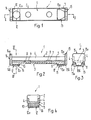
- the contact bridge 1 shown in the figures has a U-shaped carrier 2, which consists for example of steel.
- the bottom part of the carrier 2 is designated 3 and its flanges 4.
- An intermediate part 5 is fastened to the bottom part 3 of the carrier 2, preferably by brazing.
- This intermediate part 5 consists of an electrically conductive material, preferably copper, and is provided on its side facing the carrier 2 with projections 6 and 7, each of which engages in a centering hole 8 or 9 in the base part 3. Through this zen Trierlöcher 8 and 9, the intermediate part 5 is positioned during its attachment to the carrier 2.
- the intermediate part 5 On the side opposite the projections 6 and 7, the intermediate part 5 is provided in the region of its ends with elevations 10 and 11, respectively, on which contact supports 12, 13 are arranged, which are connected to the intermediate part 5 in a suitable manner, for example by brazing .
- the contact pads 12 and 13 consist of a suitable contact material, for example AgCdO.
- the carrier 2 gives the contact bridge 1 good mechanical strength, while the intermediate part 5 essentially only has the task of ensuring a good electrically conductive connection between the two contact pads 12 and 13. With a suitable design and / or choice of material, it is consequently possible to obtain a contact bridge 1 of low mass, which can withstand heavy electrical and mechanical loads.
- plate-shaped arc guide pieces 14 and 15 are connected to it, for example also by brazing.
- These arc guide pieces 14 and 15 consist of a ferromagnetic material, for example steel.
- the arcs pass directly from the contact surface 12a or 13a of the contact pads 12, 13 to the associated arc guide piece 14 or 15, the arc base points are prevented from moving laterally along the contact pads to their connection points 16, 17, which is a undesired erosion of the contact pads 12, 13 and damage to the connection points 16, 17 would result.
- the contact bridge 1 is thus protected against rapid wear by the formation of the arc guide pieces 14 and 15 even at high breaking currents, which has an advantageous effect on the service life of the contact bridge 1.
- the contact bridge can also be designed differently than described as different parts.
- the contact bridge described is particularly, if not exclusively, suitable for a contactor.
- a preferred embodiment of such a contactor is the subject of the simultaneously filed European Patent Application No. 81 109 824.3 (EP-A-79978).
Landscapes
- Arc-Extinguishing Devices That Are Switches (AREA)
- Contacts (AREA)
- Push-Button Switches (AREA)
Claims (7)
Priority Applications (5)
| Application Number | Priority Date | Filing Date | Title |
|---|---|---|---|
| EP81109823A EP0079977B1 (fr) | 1981-11-21 | 1981-11-21 | Pièce de contact pour interrupteur électrique, en particulier pour interrupteur de protection |
| AT81109823T ATE21298T1 (de) | 1981-11-21 | 1981-11-21 | Kontaktstueck fuer ein elektrisches schaltgeraet, insbesondere fuer ein schuetz. |
| DE8181109823T DE3175072D1 (en) | 1981-11-21 | 1981-11-21 | Contact piece for an electric switch apparatus, in particular for a protrective switch |
| JP57139089A JPS5889721A (ja) | 1981-11-21 | 1982-08-10 | 電気回路開閉装置の接触片 |
| US06/436,308 US4472613A (en) | 1981-11-21 | 1982-10-25 | Contact element arrangement for an electrical switching device, especially for a contactor |
Applications Claiming Priority (1)
| Application Number | Priority Date | Filing Date | Title |
|---|---|---|---|
| EP81109823A EP0079977B1 (fr) | 1981-11-21 | 1981-11-21 | Pièce de contact pour interrupteur électrique, en particulier pour interrupteur de protection |
Publications (2)
| Publication Number | Publication Date |
|---|---|
| EP0079977A1 EP0079977A1 (fr) | 1983-06-01 |
| EP0079977B1 true EP0079977B1 (fr) | 1986-08-06 |
Family
ID=8188026
Family Applications (1)
| Application Number | Title | Priority Date | Filing Date |
|---|---|---|---|
| EP81109823A Expired EP0079977B1 (fr) | 1981-11-21 | 1981-11-21 | Pièce de contact pour interrupteur électrique, en particulier pour interrupteur de protection |
Country Status (5)
| Country | Link |
|---|---|
| US (1) | US4472613A (fr) |
| EP (1) | EP0079977B1 (fr) |
| JP (1) | JPS5889721A (fr) |
| AT (1) | ATE21298T1 (fr) |
| DE (1) | DE3175072D1 (fr) |
Families Citing this family (8)
| Publication number | Priority date | Publication date | Assignee | Title |
|---|---|---|---|---|
| DE8500850U1 (de) * | 1985-01-15 | 1985-04-25 | Siemens AG, 1000 Berlin und 8000 München | Kontaktbrücke |
| SE460812B (sv) * | 1988-02-08 | 1989-11-20 | Asea Brown Boveri | Elkopplare |
| CH678989A5 (fr) * | 1989-10-04 | 1991-11-29 | Sprecher & Schuh Ag | |
| EP0736887B1 (fr) * | 1995-03-30 | 2002-05-29 | Tyco Electronics Corporation | Assemblage de contacts électriques |
| JP6213035B2 (ja) * | 2013-08-12 | 2017-10-18 | 富士電機機器制御株式会社 | 電磁接触器 |
| DE102013114401A1 (de) * | 2013-12-18 | 2015-06-18 | Eaton Industries Austria Gmbh | Schaltbrücke für Schaltgerät |
| CN104766770B (zh) | 2014-01-07 | 2017-09-08 | 西门子公司 | 断路器的静触头支架及其断路器 |
| CN107452549B (zh) * | 2016-05-31 | 2020-03-31 | 比亚迪股份有限公司 | 继电器 |
Family Cites Families (11)
| Publication number | Priority date | Publication date | Assignee | Title |
|---|---|---|---|---|
| US2340682A (en) * | 1942-05-06 | 1944-02-01 | Gen Electric | Electric contact element |
| DE1175776B (de) * | 1962-01-31 | 1964-08-13 | Siemens Ag | Kontaktbruecke fuer elektrische Schaltgeraete |
| DE1527353B2 (de) * | 1963-10-04 | 1971-06-03 | Licentia Patent Verwaltungs GmbH, 6000 Frankfurt | Schaltstueck fuer ein elektrisches schaltgeraet |
| DE1202378B (de) * | 1964-01-22 | 1965-10-07 | Siemens Ag | Elektrisches Schaltgeraet mit Schaltbruecke und Lichtbogenloeschkammer |
| JPS4216195Y1 (fr) * | 1965-05-22 | 1967-09-19 | ||
| DE1665849A1 (de) * | 1967-01-16 | 1971-04-15 | Siemens Ag | Elektrisches Schaltgeraet mit einer um ihre Querachse kippbar gelagerten Kontaktbruecke |
| FR1544754A (fr) * | 1967-09-22 | 1968-11-08 | Merlin Gerin | Dispositif de contact à pression directe |
| DE2161616C2 (de) * | 1971-12-11 | 1973-12-20 | Siemens Ag, 1000 Berlin U. 8000 Muenchen | Wannenförmige Kontaktbrücke |
| DE2647888C3 (de) * | 1976-10-22 | 1984-08-30 | Siemens AG, 1000 Berlin und 8000 München | Wannenförmige Kontaktbrücke |
| DE2916276C2 (de) * | 1979-04-21 | 1986-04-03 | Licentia Patent-Verwaltungs-Gmbh, 6000 Frankfurt | Schaltgerät |
| DE2928557A1 (de) * | 1979-07-14 | 1981-01-29 | Bbc Brown Boveri & Cie | Kontakttraeger |
-
1981
- 1981-11-21 AT AT81109823T patent/ATE21298T1/de not_active IP Right Cessation
- 1981-11-21 EP EP81109823A patent/EP0079977B1/fr not_active Expired
- 1981-11-21 DE DE8181109823T patent/DE3175072D1/de not_active Expired
-
1982
- 1982-08-10 JP JP57139089A patent/JPS5889721A/ja active Pending
- 1982-10-25 US US06/436,308 patent/US4472613A/en not_active Expired - Lifetime
Also Published As
| Publication number | Publication date |
|---|---|
| EP0079977A1 (fr) | 1983-06-01 |
| US4472613A (en) | 1984-09-18 |
| DE3175072D1 (en) | 1986-09-11 |
| JPS5889721A (ja) | 1983-05-28 |
| ATE21298T1 (de) | 1986-08-15 |
Similar Documents
| Publication | Publication Date | Title |
|---|---|---|
| DE2803249C2 (de) | Einrichtung zum Löschen von Schaltlichtbögen | |
| EP0043058A1 (fr) | Interrupteur à mercure à électrodes | |
| DE1262404B (de) | Elektrischer Leistungsschalter | |
| EP0079977B1 (fr) | Pièce de contact pour interrupteur électrique, en particulier pour interrupteur de protection | |
| DE3729504C2 (fr) | ||
| DE3530221A1 (de) | Miniaturschalter | |
| DE4018674C2 (de) | Kontaktanordnung für ein elektrisches Schaltgerät, insbesondere für ein Schütz | |
| DE3431703C2 (de) | Tastschalter | |
| DE2546423C2 (fr) | ||
| DE1298598B (de) | Vakuumschalter | |
| DE29720715U1 (de) | Schaltgerät mit Lichtbogen-Löscheinrichtung | |
| DE1207027C2 (de) | Kontaktstueck fuer elektrische schaltgeraete | |
| DE3888007T2 (de) | Schutzschalter. | |
| DE20105432U1 (de) | Blasung bei AC-Betrieb | |
| EP0079978A1 (fr) | Pièce de contact pour interrupteur électrique, en particulier pour interrupteur de protection | |
| DE1639232B1 (de) | Elektromagnetisches Relais | |
| CH647093A5 (en) | Electrical push-button switch | |
| WO2002027740A1 (fr) | Support de contact mobile pour un disjoncteur basse tension presentant une entretoise pour les levier de contact | |
| DE3628423A1 (de) | Kontaktanordnung fuer elektrische schaltgeraete | |
| DE3130952A1 (de) | Schiebeschalter | |
| EP0162801A1 (fr) | Structure de contact pour un interrupteur sous vide | |
| DE7015225U (de) | Springkontaktsatz. | |
| DE2117845A1 (de) | Kontaktanordnung für Vakuumschalter | |
| DE69402515T2 (de) | Stromunterbrechungsteil eines Schaltgerätes, insbesonders eines Schützes oder eines Schutzschalters | |
| DE3238223C2 (de) | Elektrisches Miniatur-Kompaktrelais |
Legal Events
| Date | Code | Title | Description |
|---|---|---|---|
| PUAI | Public reference made under article 153(3) epc to a published international application that has entered the european phase |
Free format text: ORIGINAL CODE: 0009012 |
|
| AK | Designated contracting states |
Designated state(s): AT BE CH DE FR GB IT LI NL SE |
|
| 17P | Request for examination filed |
Effective date: 19831110 |
|
| ITF | It: translation for a ep patent filed | ||
| GRAA | (expected) grant |
Free format text: ORIGINAL CODE: 0009210 |
|
| AK | Designated contracting states |
Kind code of ref document: B1 Designated state(s): AT BE CH DE FR GB IT LI NL SE |
|
| PG25 | Lapsed in a contracting state [announced via postgrant information from national office to epo] |
Ref country code: NL Effective date: 19860806 Ref country code: BE Effective date: 19860806 |
|
| REF | Corresponds to: |
Ref document number: 21298 Country of ref document: AT Date of ref document: 19860815 Kind code of ref document: T |
|
| ET | Fr: translation filed | ||
| REF | Corresponds to: |
Ref document number: 3175072 Country of ref document: DE Date of ref document: 19860911 |
|
| PG25 | Lapsed in a contracting state [announced via postgrant information from national office to epo] |
Ref country code: AT Effective date: 19861121 |
|
| NLV1 | Nl: lapsed or annulled due to failure to fulfill the requirements of art. 29p and 29m of the patents act | ||
| PLBI | Opposition filed |
Free format text: ORIGINAL CODE: 0009260 |
|
| 26 | Opposition filed |
Opponent name: SIEMENS AKTIENGESELLSCHAFT, BERLIN UND MUENCHEN Effective date: 19870504 |
|
| RDAG | Patent revoked |
Free format text: ORIGINAL CODE: 0009271 |
|
| STAA | Information on the status of an ep patent application or granted ep patent |
Free format text: STATUS: PATENT REVOKED |
|
| 27W | Patent revoked |
Effective date: 19890529 |
|
| REG | Reference to a national code |
Ref country code: CH Ref legal event code: PL |
|
| EUG | Se: european patent has lapsed |
Ref document number: 81109823.5 Effective date: 19891011 |