EP0079984B1 - Auge en matière plastique - Google Patents
Auge en matière plastique Download PDFInfo
- Publication number
- EP0079984B1 EP0079984B1 EP81110191A EP81110191A EP0079984B1 EP 0079984 B1 EP0079984 B1 EP 0079984B1 EP 81110191 A EP81110191 A EP 81110191A EP 81110191 A EP81110191 A EP 81110191A EP 0079984 B1 EP0079984 B1 EP 0079984B1
- Authority
- EP
- European Patent Office
- Prior art keywords
- tube
- trough
- ribs
- plastics material
- angle
- Prior art date
- Legal status (The legal status is an assumption and is not a legal conclusion. Google has not performed a legal analysis and makes no representation as to the accuracy of the status listed.)
- Expired
Links
- 239000004033 plastic Substances 0.000 title claims abstract description 30
- 229920003023 plastic Polymers 0.000 title claims abstract description 30
- 230000002787 reinforcement Effects 0.000 claims abstract description 21
- 239000000463 material Substances 0.000 claims abstract description 9
- 229920000098 polyolefin Polymers 0.000 claims abstract description 3
- 230000002093 peripheral effect Effects 0.000 claims abstract 6
- 238000002347 injection Methods 0.000 description 5
- 239000007924 injection Substances 0.000 description 5
- 238000001746 injection moulding Methods 0.000 description 5
- 239000011324 bead Substances 0.000 description 3
- 238000004519 manufacturing process Methods 0.000 description 3
- 239000004570 mortar (masonry) Substances 0.000 description 3
- 239000002990 reinforced plastic Substances 0.000 description 3
- 229910000831 Steel Inorganic materials 0.000 description 2
- 238000011031 large-scale manufacturing process Methods 0.000 description 2
- 239000002184 metal Substances 0.000 description 2
- 230000003014 reinforcing effect Effects 0.000 description 2
- 239000010959 steel Substances 0.000 description 2
- 239000004698 Polyethylene Substances 0.000 description 1
- 238000005452 bending Methods 0.000 description 1
- -1 polyethylene Polymers 0.000 description 1
- 229920000573 polyethylene Polymers 0.000 description 1
- 239000002689 soil Substances 0.000 description 1
Images


Classifications
-
- B—PERFORMING OPERATIONS; TRANSPORTING
- B65—CONVEYING; PACKING; STORING; HANDLING THIN OR FILAMENTARY MATERIAL
- B65D—CONTAINERS FOR STORAGE OR TRANSPORT OF ARTICLES OR MATERIALS, e.g. BAGS, BARRELS, BOTTLES, BOXES, CANS, CARTONS, CRATES, DRUMS, JARS, TANKS, HOPPERS, FORWARDING CONTAINERS; ACCESSORIES, CLOSURES, OR FITTINGS THEREFOR; PACKAGING ELEMENTS; PACKAGES
- B65D1/00—Rigid or semi-rigid containers having bodies formed in one piece, e.g. by casting metallic material, by moulding plastics, by blowing vitreous material, by throwing ceramic material, by moulding pulped fibrous material or by deep-drawing operations performed on sheet material
- B65D1/40—Details of walls
- B65D1/42—Reinforcing or strengthening parts or members
- B65D1/48—Reinforcements of dissimilar materials, e.g. metal frames in plastic walls
Definitions
- the invention relates to a bucket made of plastic, in particular for the transport and processing of ready-mixed mortar, of a truncated pyramid shape with an edge reinforcement made of a tube embedded in the plastic, which is bent at an obtuse angle in the region of the narrower side walls, the apex of which points upwards , and which is exposed in the area of the apex by two handle holes.
- Such a plastic bucket has become known from DE-PS-27 08 450.
- This bucket created for mortar has a fabric-reinforced plastic wall that fully encompasses the reinforcement frame made of steel in the circumferential direction of the frame parts, but leaves open areas of the frame on the end faces in the direction of extension of the frame parts that serve as eyelets for crane hooks or the like, with on the outside of the container reinforcing ribs are arranged.
- the production of fabric-reinforced plastic is very labor intensive. Therefore, such buckets are quite expensive to manufacture. The manufacture of such fabric-reinforced plastic buckets is not suitable for large-scale production.
- buckets according to DE-PS-11 49292 which have an edge reinforcement in the form of an annularly bent metal tube, which is completely surrounded by the plastic and have an impact at least at one point on their circumference, have proven effective, the ends of the metal tube being able to be inserted by means of an insertable interior -or a push-on outer sleeve are connected to each other.
- two opposing partial sections of the tube that forms the edge reinforcement are not overmolded, but are exposed and serve as handles or as attack surfaces for crane hooks.
- the invention improves the bucket of the type mentioned and solves the problem on which it is based in that the plastic is a polyolefin, in particular polyethylene, that the edge reinforcement is connected by two tube parts of the same shape in the middle of the long sides by two slipped sleeves that in the plastic surrounding the edge reinforcement is alternately arranged outside the sleeves, pairs of vertically radially directed holes on the pipe center and vertically extending slots tangentially adjacent to the pipe and that vertically downwardly extending short ribs are arranged on the edge of the handle holes, the width of which Corresponds to the width of the tube-reinforced edge.
- the plastic is a polyolefin, in particular polyethylene
- the edge reinforcement is connected by two tube parts of the same shape in the middle of the long sides by two slipped sleeves that in the plastic surrounding the edge reinforcement is alternately arranged outside the sleeves, pairs of vertically radially directed holes on the pipe center and vertically extending slots tangentially adjacent to the pipe and that vertically downwardly extending short ribs are
- Such a bucket can be cheaply produced as a mass-produced article by injection molding.
- the manual work involved is extremely low, it only consists of inserting the pipe and socket parts into the injection mold. These are precisely centered in the injection mold between pins, which are expressed in the edge reinforcement as holes which are directed radially vertically onto the tube means, and by means of projections in the shape, which are expressed as vertical slots in the plastic which are tangential to the side of the tube, so that the thickness of the plastic surrounding the steel pipe and the sleeves is the same everywhere. This is very important for the stability of the bucket.
- vertically downwardly extending short ribs are arranged on the edge of the handle holes, the width of which corresponds to the width of the tube-reinforced edge. These ribs prevent the pipe from being torn out of the surrounding plastic bed or the edge of the plastic from being torn open.
- the internal slot on the edge reinforcement has a base that is angled.
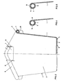
- the truncated pyramid-shaped bucket has longitudinal side walls 1, end side walls 2 and a bottom 3.
- the side walls 1, 2 are provided at the top with an edge reinforcement tube 4 and sleeves 5 including edge 6.
- the tubes 4 and the sleeves 5 are completely surrounded by plastic in the area of the long sides 1.
- the tubes 4 only emerge in a partial area of the side walls without plastic sheathing, in the area of the recesses 7 serving as hand or crane hook holes.
- the tube 4 is angled at an obtuse angle, preferably 40 °. The apex of this bend points upwards.
- the sleeves 5 connecting the two pipe parts 4 are arranged in the middle of the long sides.
- the bottom 3 has ribs 9 on the underside, the height of which is only small and suitably corresponds to the thickness of the wall material. These ribs have less of a reinforcing function than the function of preventing the soil material from being ground down when the bucket is being ground on the ground.
- the plastic casing 6 has holes 10 in the area of the edge reinforcement, which extend vertically and radially to the center of the tube 4. These holes come from pins in the injection mold, which were used for the horizontal centering of the tube 4 during the injection molding.
- the casing 6 also has slots 11 and 12, which also served to center the tube 4 in the injection mold during the injection molding process. These slots 11, 12 run essentially vertically and tangentially to the tube 4. They can be angular or rounded. They come from projections in the shape that were used to center the tube 4. After opening the injection mold, these holes and slots are used to check that the casing 6 around the pipe 4 is equally strong.
- the slot 12 has a base which is angled and encloses an angle of preferably 135 °. This bending ensures that the plastic of the wall merges seamlessly into the plastic of the casing. Centering holes can also be made where the sleeve 5 is located. These centering holes and centering slots 11, 12 are of great importance for the durability of the buckets because they ensure the uniform thickness of the plastic sheathing. These holes 10 and slots 11, 12 generally do not connect the tube 4 to the outside atmosphere because a very thin plastic skin has formed at the bottom of the holes 10 and the slots 11, 12 during the injection molding process.
- short ribs 13 are attached below the edge to the outside, which preferably have the same length as the ribs 8.
Landscapes
- Engineering & Computer Science (AREA)
- Ceramic Engineering (AREA)
- Mechanical Engineering (AREA)
- Springs (AREA)
- Extrusion Moulding Of Plastics Or The Like (AREA)
- Processing And Handling Of Plastics And Other Materials For Molding In General (AREA)
- Moulds For Moulding Plastics Or The Like (AREA)
- Sewage (AREA)
- Details Of Rigid Or Semi-Rigid Containers (AREA)
Claims (4)
Priority Applications (1)
| Application Number | Priority Date | Filing Date | Title |
|---|---|---|---|
| AT81110191T ATE12920T1 (de) | 1981-11-25 | 1981-12-05 | Kuebel aus kunststoff. |
Applications Claiming Priority (2)
| Application Number | Priority Date | Filing Date | Title |
|---|---|---|---|
| DE3146685 | 1981-11-25 | ||
| DE3146685A DE3146685A1 (de) | 1981-11-25 | 1981-11-25 | "kuebel aus kunststoff" |
Publications (3)
| Publication Number | Publication Date |
|---|---|
| EP0079984A2 EP0079984A2 (fr) | 1983-06-01 |
| EP0079984A3 EP0079984A3 (en) | 1983-06-29 |
| EP0079984B1 true EP0079984B1 (fr) | 1985-04-24 |
Family
ID=6147169
Family Applications (1)
| Application Number | Title | Priority Date | Filing Date |
|---|---|---|---|
| EP81110191A Expired EP0079984B1 (fr) | 1981-11-25 | 1981-12-05 | Auge en matière plastique |
Country Status (3)
| Country | Link |
|---|---|
| EP (1) | EP0079984B1 (fr) |
| AT (1) | ATE12920T1 (fr) |
| DE (2) | DE3146685A1 (fr) |
Families Citing this family (1)
| Publication number | Priority date | Publication date | Assignee | Title |
|---|---|---|---|---|
| GB2143479B (en) * | 1983-07-11 | 1987-02-18 | Glasdon Ltd | Improvements in or relating to bins |
Family Cites Families (3)
| Publication number | Priority date | Publication date | Assignee | Title |
|---|---|---|---|---|
| DE1149292B (de) * | 1960-01-25 | 1963-05-22 | Friedrich Stuckenbroeker | Randverstaerkung fuer Transportbehaelter aus Kunststoff |
| FR1379277A (fr) * | 1963-12-26 | 1964-11-20 | Cogindus | Bac pour manutention ou autres usages |
| DE2708450C3 (de) * | 1977-02-26 | 1980-12-11 | Staba Handels- Und Transportgesellschaft Mbh, 4720 Beckum | Transportbehälter für Mörtel |
-
1981
- 1981-11-25 DE DE3146685A patent/DE3146685A1/de not_active Withdrawn
- 1981-12-05 DE DE8181110191T patent/DE3170197D1/de not_active Expired
- 1981-12-05 AT AT81110191T patent/ATE12920T1/de not_active IP Right Cessation
- 1981-12-05 EP EP81110191A patent/EP0079984B1/fr not_active Expired
Also Published As
| Publication number | Publication date |
|---|---|
| EP0079984A2 (fr) | 1983-06-01 |
| DE3146685A1 (de) | 1983-06-01 |
| DE3170197D1 (en) | 1985-05-30 |
| EP0079984A3 (en) | 1983-06-29 |
| ATE12920T1 (de) | 1985-05-15 |
Similar Documents
| Publication | Publication Date | Title |
|---|---|---|
| EP0371917B1 (fr) | Cadre de couronnement pour canal de drainage | |
| DE2437809C3 (de) | Siebboden sowie Siebkörper und Rahmen hierfür | |
| EP0009764B1 (fr) | Convoyeur à deux bandes superposées | |
| EP0515819A2 (fr) | Récipient de stockage ou de transport | |
| DE7305361U (de) | Palette aus Kunststoff | |
| CH672295A5 (fr) | ||
| DE2041623A1 (de) | Palettenaufbau | |
| DE3323090A1 (de) | Eierschachtel | |
| DE2703721C2 (de) | Eimer aus Kunststoff | |
| DE2200512C3 (de) | Abstandhalter fur Bewehrungsstäbe | |
| DE9206973U1 (de) | Lager- und Transportbehälter aus Kunststoff | |
| DE69001800T2 (de) | Behälterverschluss mit Metallkörper und Kunststoff-Griffteil. | |
| DE68902446T2 (de) | Kaeseform aus kunststoff mit waehrend der herstellung der seitenwand durch spritzgiessen geformten draenagerillen. | |
| EP0079984B1 (fr) | Auge en matière plastique | |
| DE2805880A1 (de) | Keimbehaelter | |
| EP0297258A2 (fr) | Coquille pour la coulée continue de profiles d'entrées pour laminage de poutrelles | |
| DE20105030U1 (de) | Vorrichtung zur Lagerung von Flüssigkeiten | |
| EP0080197B1 (fr) | Auge en matière plastique | |
| EP0329001A1 (fr) | Dispositif d'enlèvement de débris et de matériaux en vrac comparables | |
| DE9309301U1 (de) | Schacht oder Behälter | |
| DE202007002790U1 (de) | Gleichlaufeinrichtung für Hubvorrichtungen | |
| WO1988000915A1 (fr) | Reservoir collecteur pour produit reutilisable | |
| DE2317594C3 (de) | Käseform zum Herstellen von Käse mit einer dichten Käserinde, insbesondere zum Herstellen von gepreßtem Käse | |
| DE69904160T2 (de) | Formen für Behälter mit Henkel | |
| DE29912902U1 (de) | Großvolumiger Behälter zur Aufnahme von flüssigen Medien |
Legal Events
| Date | Code | Title | Description |
|---|---|---|---|
| PUAI | Public reference made under article 153(3) epc to a published international application that has entered the european phase |
Free format text: ORIGINAL CODE: 0009012 |
|
| PUAL | Search report despatched |
Free format text: ORIGINAL CODE: 0009013 |
|
| AK | Designated contracting states |
Designated state(s): AT BE CH DE FR GB IT LI LU NL SE |
|
| AK | Designated contracting states |
Designated state(s): AT BE CH DE FR GB IT LI LU NL SE |
|
| 17P | Request for examination filed |
Effective date: 19830829 |
|
| ITF | It: translation for a ep patent filed | ||
| GRAA | (expected) grant |
Free format text: ORIGINAL CODE: 0009210 |
|
| AK | Designated contracting states |
Designated state(s): AT BE CH DE FR GB IT LI LU NL SE |
|
| REF | Corresponds to: |
Ref document number: 12920 Country of ref document: AT Date of ref document: 19850515 Kind code of ref document: T |
|
| REF | Corresponds to: |
Ref document number: 3170197 Country of ref document: DE Date of ref document: 19850530 |
|
| ET | Fr: translation filed | ||
| PG25 | Lapsed in a contracting state [announced via postgrant information from national office to epo] |
Ref country code: LU Free format text: LAPSE BECAUSE OF NON-PAYMENT OF DUE FEES Effective date: 19851231 |
|
| PLBE | No opposition filed within time limit |
Free format text: ORIGINAL CODE: 0009261 |
|
| STAA | Information on the status of an ep patent application or granted ep patent |
Free format text: STATUS: NO OPPOSITION FILED WITHIN TIME LIMIT |
|
| 26N | No opposition filed | ||
| PGFP | Annual fee paid to national office [announced via postgrant information from national office to epo] |
Ref country code: AT Payment date: 19861215 Year of fee payment: 6 |
|
| PGFP | Annual fee paid to national office [announced via postgrant information from national office to epo] |
Ref country code: NL Payment date: 19861231 Year of fee payment: 6 |
|
| PG25 | Lapsed in a contracting state [announced via postgrant information from national office to epo] |
Ref country code: AT Effective date: 19871205 |
|
| PG25 | Lapsed in a contracting state [announced via postgrant information from national office to epo] |
Ref country code: SE Effective date: 19871206 |
|
| PG25 | Lapsed in a contracting state [announced via postgrant information from national office to epo] |
Ref country code: LI Effective date: 19871231 Ref country code: CH Effective date: 19871231 Ref country code: BE Effective date: 19871231 |
|
| BERE | Be: lapsed |
Owner name: STUCKI KUNSTSTOFFWERK UND WERKZEUGBAU G.M.B.H. Effective date: 19871231 |
|
| PG25 | Lapsed in a contracting state [announced via postgrant information from national office to epo] |
Ref country code: NL Effective date: 19880701 |
|
| NLV4 | Nl: lapsed or anulled due to non-payment of the annual fee | ||
| GBPC | Gb: european patent ceased through non-payment of renewal fee | ||
| PG25 | Lapsed in a contracting state [announced via postgrant information from national office to epo] |
Ref country code: FR Free format text: LAPSE BECAUSE OF NON-PAYMENT OF DUE FEES Effective date: 19880831 |
|
| REG | Reference to a national code |
Ref country code: CH Ref legal event code: PL |
|
| PG25 | Lapsed in a contracting state [announced via postgrant information from national office to epo] |
Ref country code: DE Effective date: 19880901 |
|
| REG | Reference to a national code |
Ref country code: FR Ref legal event code: ST |
|
| PG25 | Lapsed in a contracting state [announced via postgrant information from national office to epo] |
Ref country code: GB Free format text: LAPSE BECAUSE OF NON-PAYMENT OF DUE FEES Effective date: 19881121 |
|
| EUG | Se: european patent has lapsed |
Ref document number: 81110191.4 Effective date: 19880912 |