EP0080000A1 - Dispositif d'accouplement pour contrôler les cadres d'un métier à tisser - Google Patents
Dispositif d'accouplement pour contrôler les cadres d'un métier à tisser Download PDFInfo
- Publication number
- EP0080000A1 EP0080000A1 EP81810469A EP81810469A EP0080000A1 EP 0080000 A1 EP0080000 A1 EP 0080000A1 EP 81810469 A EP81810469 A EP 81810469A EP 81810469 A EP81810469 A EP 81810469A EP 0080000 A1 EP0080000 A1 EP 0080000A1
- Authority
- EP
- European Patent Office
- Prior art keywords
- stop
- pawl
- moved
- sinker
- board
- Prior art date
- Legal status (The legal status is an assumption and is not a legal conclusion. Google has not performed a legal analysis and makes no representation as to the accuracy of the status listed.)
- Withdrawn
Links
Images

Classifications
-
- D—TEXTILES; PAPER
- D03—WEAVING
- D03C—SHEDDING MECHANISMS; PATTERN CARDS OR CHAINS; PUNCHING OF CARDS; DESIGNING PATTERNS
- D03C1/00—Dobbies
Definitions
- the invention relates to a coupling arrangement for controlling the shafts of a weaving machine, with an intermittently rotating drive shaft having at least one groove and a pawl which can be coupled into the groove and is arranged on an eccentric rotatably mounted on the drive shaft, and with a tab of a crank rod which encloses the eccentric for the stroke to the shafts and at least one control lever which can be moved in the path of the pawl and disengages them and which can be pivoted back and forth by a circuit board which can be coupled into a lifting knife drive.
- the stop for the circuit board is arranged in a stationary manner.
- the cooperation between the circuit board and the stop can become uncertain in this known embodiment.
- it can e.g. B. occur that the board at the beginning of the locking process, where it is moved against the stationary stop, hits in an undesirable manner with its approach against the stop and possibly thrown back into the linear drive can be. This means that the locking is initiated late or made impossible. Operation is disrupted.
- the invention has for its object to provide a coupling arrangement which is particularly improved in this regard.
- the invention consists in that the circuit board is driven, with the interposition of a spring, by a lifting part which is at the same time designed as a resilient scanning element for scanning an associated program control device.
- a lifting part which is at the same time designed as a resilient scanning element for scanning an associated program control device.
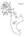
- a drive shaft 1 which is set in rotation by 180 ° from the main shaft of the weaving machine in each case, contains two grooves 2, into which the nose 3 of a coupling pawl 5 pivotably mounted at 4 and acting under the action of a tension spring 60 can engage.
- the pawl 5 is mounted on an eccentric 6 rotatably mounted on shaft 1, which is enclosed by a tab 7. This is articulated at 8 to a transmission linkage 9, via which the back and forth movement of the tab 7, which arises in accordance with arrow 11, is transmitted to an associated shaft of a weaving machine.
- the entire parts 1, 6, 7 form the so-called eccentric machine for driving and controlling all heald frames the weaving machine.
- the shafts are moved according to a binding program for the warp threads in the up and down positions.
- two control levers 14, 15 and 16, 17 pivotally mounted on the fixed bearing pins 12, 13 are installed, which have hooks 18 at the free ends, which can be pivoted into the web of the pawl 5.
- the two control levers are connected to the arms 15, 17 at 21 by a joint.
- a plate 23 is pivotally mounted at 22, which can be coupled with a reciprocating knife 25 moved back and forth according to arrow 24.
- the board 23 has a fork-shaped part 26 which forms a slot 27.
- the board 23 In the upper position shown in FIG. 2, the board 23 is disengaged from the lifting knife 25, in the lower position 26a, indicated by dashed lines, the board cooperates with the lifting knife 25. It is moved back and forth by the latter, so that the levers 14-17 to be pivoted about their journals 12, 13.
- Stop 83 is fastened by means of a screw 84 to a two-armed lever 86, 87 which can be pivoted by 85. Stop 83 in FIG. 2 extends perpendicular to the plane of the drawing over all drive parts 14 - 17, 23 belonging to the shafts and is attached at its other end facing away from the viewer to a further lever corresponding to lever 86, 87.
- a bolt 89 engages in the fork-shaped, free end 88 of the arm 87 and sits on an arm 91 of a three-armed lever 91, 92, 93 which can be pivoted about 94.
- the lever 91-93 is moved back and forth during operation in accordance with arrow 95, so that the bolt 89 is moved back and forth in the slot of the end 88 and thereby pivots the lever 86, 87 back and forth by 85.
- the mode of action is as follows.
- the lifting knife 25 and the stop 83 are continuously driven in opposite directions during operation, ie when the lifting knife 25 moves to the left the stop 83 is moved to the right and vice versa.
- the stop 83 is in the right-hand position shown in broken lines. Now the board 23 and thus the hook-shaped end 82 is moved upwards. The end 82 engages behind the stop 83 with a relatively large clearance A.
- the arm 17 is in contact with the fixed stop 54, on which it is held under the action of the tension spring 55. Since the parts 23, 14-17 are locked, it is prevented that, for example as a result of machine vibrations, the hooks 18 of the levers 14-17 can momentarily be moved outwards, as a result of which the pawl 5 could be engaged in an undesirable manner.
- the unlocking of the board 23 from the stop 83 proceeds as follows. First, the lifting knife 25 is moved to the left. In the meantime, the lever 91-93 is pivoted counterclockwise, the lever 86, 87 clockwise, whereby the stop 83 is moved to the right and the play A is restored. As soon as the lifting knife 25 has reached its left position, the board 23 is moved downward by means of the drive pin 28 moved down to the position 26a, in which it can be gripped by the lifting knife 25 depending on the program. If the lifting knife 25 Fig. 1 runs to the right, z. B. board 23 taken. As a result, the ends 18 of the levers 14-17 are pivoted outward, so that the pawl 5 is coupled back into the shaft 1 under the action of the tension spring 60. As shaft 1 rotates further in sections, the shaft is moved back into the low or high position. It is moved back and forth until the pawl 5 is disengaged again. This is done in the manner described above.
Landscapes
- Engineering & Computer Science (AREA)
- Textile Engineering (AREA)
- Looms (AREA)
Priority Applications (1)
| Application Number | Priority Date | Filing Date | Title |
|---|---|---|---|
| EP81810469A EP0080000A1 (fr) | 1981-11-25 | 1981-11-25 | Dispositif d'accouplement pour contrôler les cadres d'un métier à tisser |
Applications Claiming Priority (1)
| Application Number | Priority Date | Filing Date | Title |
|---|---|---|---|
| EP81810469A EP0080000A1 (fr) | 1981-11-25 | 1981-11-25 | Dispositif d'accouplement pour contrôler les cadres d'un métier à tisser |
Publications (1)
| Publication Number | Publication Date |
|---|---|
| EP0080000A1 true EP0080000A1 (fr) | 1983-06-02 |
Family
ID=8188684
Family Applications (1)
| Application Number | Title | Priority Date | Filing Date |
|---|---|---|---|
| EP81810469A Withdrawn EP0080000A1 (fr) | 1981-11-25 | 1981-11-25 | Dispositif d'accouplement pour contrôler les cadres d'un métier à tisser |
Country Status (1)
| Country | Link |
|---|---|
| EP (1) | EP0080000A1 (fr) |
Citations (6)
| Publication number | Priority date | Publication date | Assignee | Title |
|---|---|---|---|---|
| DE2018296A1 (de) * | 1969-05-06 | 1971-02-04 | Gebr Staubh & Co, Horgen (Schweiz) | Schaftmaschine |
| DE2116697A1 (en) * | 1971-04-06 | 1972-10-19 | Gebrüder Brock, 4060 Yiersen | Double lifters for dobby loom - with angled faces to match firm holding blades to eliminate free play |
| FR2178029A1 (fr) * | 1972-03-28 | 1973-11-09 | Staeubli Ag | |
| FR2398229A1 (fr) * | 1977-07-21 | 1979-02-16 | Sulzer Ag | Embrayage de declenchement du deplacement d'un element d'une machine textile |
| EP0047791A1 (fr) * | 1980-09-12 | 1982-03-24 | GebràDer Sulzer Aktiengesellschaft | Dispositif d'accouplement pour la commande des cadres d'un métier à tisser |
| EP0049707A1 (fr) * | 1980-10-10 | 1982-04-21 | GebràDer Sulzer Aktiengesellschaft | Dispositif d'accouplement pour la commande des cadres d'un métier à tisser |
-
1981
- 1981-11-25 EP EP81810469A patent/EP0080000A1/fr not_active Withdrawn
Patent Citations (6)
| Publication number | Priority date | Publication date | Assignee | Title |
|---|---|---|---|---|
| DE2018296A1 (de) * | 1969-05-06 | 1971-02-04 | Gebr Staubh & Co, Horgen (Schweiz) | Schaftmaschine |
| DE2116697A1 (en) * | 1971-04-06 | 1972-10-19 | Gebrüder Brock, 4060 Yiersen | Double lifters for dobby loom - with angled faces to match firm holding blades to eliminate free play |
| FR2178029A1 (fr) * | 1972-03-28 | 1973-11-09 | Staeubli Ag | |
| FR2398229A1 (fr) * | 1977-07-21 | 1979-02-16 | Sulzer Ag | Embrayage de declenchement du deplacement d'un element d'une machine textile |
| EP0047791A1 (fr) * | 1980-09-12 | 1982-03-24 | GebràDer Sulzer Aktiengesellschaft | Dispositif d'accouplement pour la commande des cadres d'un métier à tisser |
| EP0049707A1 (fr) * | 1980-10-10 | 1982-04-21 | GebràDer Sulzer Aktiengesellschaft | Dispositif d'accouplement pour la commande des cadres d'un métier à tisser |
Similar Documents
| Publication | Publication Date | Title |
|---|---|---|
| EP0109999B1 (fr) | Ratière pour métier à tisser | |
| DE2741199A1 (de) | Kupplung zur bewegung eines maschinenteils einer textilmaschine | |
| EP0047791B1 (fr) | Dispositif d'accouplement pour la commande des cadres d'un métier à tisser | |
| DE2942573C2 (fr) | ||
| EP0082906B2 (fr) | Dispositif d'accouplement pour la commande des cadres d'un métier à tisser | |
| EP0048292B1 (fr) | Dispositif d'accouplement pour la commande des cadres d'un métier à tisser | |
| CH688320A5 (de) | Webstuhl. | |
| EP0129123A2 (fr) | Mécanique d'armure | |
| DE69102716T3 (de) | Schaltmechanismus für die Bewegung des Greiferrahmens einer Fachbildungsvorrichtung. | |
| EP0050160A1 (fr) | Dispositif d'accouplement pour la commande des cadres d'un métier à tisser | |
| DE2832629C2 (de) | Schaftmaschine für Webmaschinen | |
| DE3004969C2 (fr) | ||
| EP0080547A1 (fr) | Procédé de fonctionnement d'un dispositif d'accouplement pour contrôler les cadres d'un métier à tisser et le dispositif d'accouplement lui-même | |
| EP0049707B1 (fr) | Dispositif d'accouplement pour la commande des cadres d'un métier à tisser | |
| DE3501241C2 (de) | Vorrichtung zum Unterbrechen des Antriebs eines bewegten mechanischen Organs, insbesondere einer Papierzange einer Verpackungsmaschine | |
| DE2932679C2 (fr) | ||
| DE2918062B2 (de) | Antriebsmechanismus für das Blatt und die Webkantennadel einer Bandwebmaschine | |
| DE3332637C2 (fr) | ||
| DE2041821C3 (de) | Vorrichtung zur Herstellung einer Schnittleiste | |
| DE2814406A1 (de) | Antriebsvorrichtung fuer einen teilmechanismus einer webmaschine | |
| DE1611908C3 (de) | Doppelthebende Schaftmaschine für Webstühle | |
| DE562152C (de) | Kartenzylinderschaltvorrichtung | |
| DE1950401C (de) | Schemelschaftmaschine | |
| DE2041055A1 (de) | Umschaltvorrichtung fuer Typentraeger von elektrischen Schreibmaschinen | |
| DE761426C (de) | Schreibrechenmaschinen mit selbsttaetiger Summenzugvorrichtung |
Legal Events
| Date | Code | Title | Description |
|---|---|---|---|
| PUAI | Public reference made under article 153(3) epc to a published international application that has entered the european phase |
Free format text: ORIGINAL CODE: 0009012 |
|
| 17P | Request for examination filed |
Effective date: 19811127 |
|
| AK | Designated contracting states |
Designated state(s): CH LI |
|
| STAA | Information on the status of an ep patent application or granted ep patent |
Free format text: STATUS: THE APPLICATION HAS BEEN WITHDRAWN |
|
| RBV | Designated contracting states (corrected) |
Designated state(s): CH LI |
|
| 18W | Application withdrawn |
Withdrawal date: 19830712 |
|
| RIN1 | Information on inventor provided before grant (corrected) |
Inventor name: JUELICH, WERNER |