EP0080090A1 - Installation pour le transfert de chaleur - Google Patents
Installation pour le transfert de chaleur Download PDFInfo
- Publication number
- EP0080090A1 EP0080090A1 EP82110183A EP82110183A EP0080090A1 EP 0080090 A1 EP0080090 A1 EP 0080090A1 EP 82110183 A EP82110183 A EP 82110183A EP 82110183 A EP82110183 A EP 82110183A EP 0080090 A1 EP0080090 A1 EP 0080090A1
- Authority
- EP
- European Patent Office
- Prior art keywords
- heat exchanger
- heat
- exhaust gas
- air
- transfer device
- Prior art date
- Legal status (The legal status is an assumption and is not a legal conclusion. Google has not performed a legal analysis and makes no representation as to the accuracy of the status listed.)
- Ceased
Links
- 238000009434 installation Methods 0.000 title abstract description 4
- 239000007789 gas Substances 0.000 claims description 48
- 238000010438 heat treatment Methods 0.000 claims description 32
- 239000002918 waste heat Substances 0.000 claims description 13
- 238000013022 venting Methods 0.000 claims description 2
- 238000001556 precipitation Methods 0.000 claims 1
- 231100000331 toxic Toxicity 0.000 abstract description 2
- 230000002588 toxic effect Effects 0.000 abstract description 2
- 238000009423 ventilation Methods 0.000 description 6
- 238000000926 separation method Methods 0.000 description 4
- XLYOFNOQVPJJNP-UHFFFAOYSA-N water Substances O XLYOFNOQVPJJNP-UHFFFAOYSA-N 0.000 description 4
- LYCAIKOWRPUZTN-UHFFFAOYSA-N Ethylene glycol Chemical compound OCCO LYCAIKOWRPUZTN-UHFFFAOYSA-N 0.000 description 2
- 238000010079 rubber tapping Methods 0.000 description 2
- UGFAIRIUMAVXCW-UHFFFAOYSA-N Carbon monoxide Chemical compound [O+]#[C-] UGFAIRIUMAVXCW-UHFFFAOYSA-N 0.000 description 1
- 230000005540 biological transmission Effects 0.000 description 1
- 229910002091 carbon monoxide Inorganic materials 0.000 description 1
- 238000010276 construction Methods 0.000 description 1
- 238000001816 cooling Methods 0.000 description 1
- 230000001419 dependent effect Effects 0.000 description 1
- 238000011161 development Methods 0.000 description 1
- 230000018109 developmental process Effects 0.000 description 1
- 230000006870 function Effects 0.000 description 1
- WGCNASOHLSPBMP-UHFFFAOYSA-N hydroxyacetaldehyde Natural products OCC=O WGCNASOHLSPBMP-UHFFFAOYSA-N 0.000 description 1
- 239000007788 liquid Substances 0.000 description 1
- 239000003921 oil Substances 0.000 description 1
- 238000005086 pumping Methods 0.000 description 1
- 239000004449 solid propellant Substances 0.000 description 1
Images


Classifications
-
- F—MECHANICAL ENGINEERING; LIGHTING; HEATING; WEAPONS; BLASTING
- F28—HEAT EXCHANGE IN GENERAL
- F28D—HEAT-EXCHANGE APPARATUS, NOT PROVIDED FOR IN ANOTHER SUBCLASS, IN WHICH THE HEAT-EXCHANGE MEDIA DO NOT COME INTO DIRECT CONTACT
- F28D15/00—Heat-exchange apparatus with the intermediate heat-transfer medium in closed tubes passing into or through the conduit walls ; Heat-exchange apparatus employing intermediate heat-transfer medium or bodies
-
- F—MECHANICAL ENGINEERING; LIGHTING; HEATING; WEAPONS; BLASTING
- F24—HEATING; RANGES; VENTILATING
- F24D—DOMESTIC- OR SPACE-HEATING SYSTEMS, e.g. CENTRAL HEATING SYSTEMS; DOMESTIC HOT-WATER SUPPLY SYSTEMS; ELEMENTS OR COMPONENTS THEREFOR
- F24D11/00—Central heating systems using heat accumulated in storage masses
- F24D11/006—Central heating systems using heat accumulated in storage masses air heating system
- F24D11/009—Central heating systems using heat accumulated in storage masses air heating system with recuperation of waste heat
Definitions
- the present invention relates to a heat transfer device according to the preamble of the main claim.
- the heat flows occurring within a building preferably a single-family house, for example the exhaust air from the kitchen or the bathroom and the exhaust gases of a fuel-heated heat source in an exhaust gas / exhaust air line, are to be combined and lead to a heat exchanger together, the Fresh air is supplied in counterflow from the atmosphere, which is supplied to individual rooms in the building after heating in the heat exchanger.
- the known solution consists of a large number of components and accordingly requires a high level of installation effort. Furthermore, it is not guaranteed that the exhaust air heat source and the fuel-heated heat source are uniformly available as energy sources for supplying the supply air heat exchanger at foreseeable times.
- the use of the exhaust gas in direct heat exchange with the supply air in the event of leaks in the area of the exhaust gas / supply air heat exchanger entails dangers for people living in the house, since the risk cannot be excluded that toxic components of the exhaust gas (carbon monoxide) are mixed into the supply air .
- the object of the present invention is to enable the waste heat flows occurring in a building to be used safely in order to heat the fresh air or circulating air to be supplied to the rooms in the building.
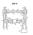
- Figure nine shows the possibility of inserting a memory
- Transmission device is schematically shown with 1, a room of a residential or industrial building, in which at least one fuel-heated heat source 2, be it a boiler, circulating water heater, continuous water heater, heating oven or the like, is installed. Furthermore, the room itself, if it is provided with a ventilation device 3, represents an exhaust air heat source. Ventilation openings are provided on the room 1, preferably on the ceiling, with which exhaust air can be guided to a collection point 5 via an air duct 4.
- the fuel-heated heat source 2 usually has an exhaust pipe 6, which is also led to the collection point 5. It does not matter whether the fuel-heated heat source 2 is fed by gas, oil or solid fuels.
- the collecting point 5 can either be supplied with exhaust air from several rooms 1, there is also the possibility of bringing together two exhaust pipes at the collecting point 5 from a plurality of heat sources. There is also the further possibility of bringing together several exhaust air ducts as well as exhaust pipes in the area of the collection point.
- a common waste heat line 7 goes from the collection point 5 to an exhaust gas / exhaust air heat exchanger 8, from which it is led into the atmosphere via a chimney 9.
- the waste heat exchanger 8 is connected via lines 10 and 11 to a supply air or circulating air heat exchanger 12, the lines 10 and 11 forming elements of an intermediate medium circuit which contains, for example, water or glycol and in which the intermediate medium may be with the aid of a pump (not shown) or a fan is moved.
- a circulating air line 13, into which a blower 14 is switched on, is connected to the circulating air heat exchanger.
- the circulation line 13 leads in the direction of flow first via the circulating air heat exchanger 12 and then via a heating line 14 into a room 15 to be heated, which room can be a room different from room 1, but can also be the same room.
- the function of the heat transfer device described according to FIG 15 belong, or the control devices of the heating and ventilation system.
- the waste heat from both is collected and transferred to the waste heat exchanger 8 via the waste heat line 7.
- the intermediate circuit of the intermediate medium is heated, which emits its heat to the fresh / circulating air heat exchanger 12.
- the fresh air / circulating air heat exchanger preheats the circulating air to be given into space 15.
- the circulating air heat exchanger can be equipped with a constant outlet temperature control or be provided with heat pipes.
- the exhaust pipe of the individual fuel-heated heat source 2 or the combined exhaust pipes of several fuel-heated heat sources are combined on a separate exhaust gas heat exchanger 20.
- the exhaust gas heat exchanger acts as an exhaust air heat exchanger during downtimes.
- the exhaust air and exhaust gas heat exchanger can form a structural unit.
- the combined vents 3 of all rooms 1 to be vented are combined in a common exhaust air line 4 and placed on a separate exhaust air heat exchanger 21.
- the intermediate medium line 10 has a branch from which a line 24 branches off, likewise there is a branch in the line 11 in which a line 25 opens into the line 11. While the line 10, the intermediate medium in the cooled to was conveyed from the supply air heat exchanger 12 into the exhaust air heat exchanger 21, the exhaust gas heat exchanger 20 is hydraulically connected in parallel to the exhaust air heat exchanger 21 through the lines 24 and 25.
- the fuel-heated heat source 2 is located in the room 30 and is connected via the exhaust pipe 6 to the exhaust gas heat exchanger 20, which is connected directly to the chimney 9.
- a vent 3 is provided, which is connected via a guide 4 to the exhaust air heat exchanger 21, which conveys the exhaust air into the atmosphere via a special pipe 31.
- the supply air duct 22 is also provided, which runs through the supply air heat exchanger 12 and heats a space 32 via a heating line 23, which is connected via a line 33 to the atmosphere as a vent.
- the routing of the intermediate medium differs from the previous examples according to FIGS.
- FIG. Four shows that a heat pipe 37, one end 38 of which can be used as the heat exchange element for the heat transfer device is acted upon by the combined exhaust gas / exhaust air heat exchanger 8, while the other end 39 is assigned to the supply air heat exchanger 12.
- the heat pipe has a liquid which is evaporated in the end 38 under the action of heat supplied.
- the steam reaches the end 39 and condenses on account of the heat given off to the supply air brought in in the duct 22.
- the condensed heat transfer medium flows back to the end 38 at the bottom of the heat pipe due to a slope or pumping action, and the cycle begins again.
- the supply air heat exchanger 12 is divided into several sections that have no connection with one another.
- the supply air duct 22 is led to a separation point 40, from which individual supply air lines 41, 42 and 43 depart, which are supplied via separate heating lines 44 45 and 46 to different rooms 47, 48 and 49 to be heated with hot air.
- the rooms 47 to 49 can be those in which fuel-heated heat sources are installed or which in turn are to be vented by a venting device 3.
- the figure six teaches that instead of a single intermediate circuit, two intermediate circuits 50 and 51 can be provided, each having lines 10 and 11. It is advantageous here to assign one intermediate medium circuit to the exhaust air heat exchanger 21 and the other to the exhaust gas heat exchanger 20.
- the common supply air line 22 is again led to the separation point 40, from which channels 41 and 42 branch, which lead to a supply air heat exchanger split into two elements 52 and 53. It is provided that the supply air heat exchanger element 52 is connected to a room 49 via a heating line 44, while the supply air heat exchanger element 53 is connected to the other room 48 via a heating line 45. Both rooms 48 and 49 can be vented via separate vent lines 33. It is also possible to vent these rooms via the ventilation device 3.
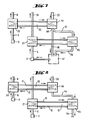
- FIG. Seven a construction of the circuit according to FIG. 6 is possible to lead the supply air in parallel instead of from the separation point 40 in such a way that basic heating of the supply air takes place in a basic heating heat exchanger element 54 and that the separation point 40 lies at the outlet of this basic heating element.
- a heating duct 46 is then led to the basic heating element directly to a room 47, another heating duct is guided via the post-heating element 55, the output line 56 of which is supplied either in the same room 47 or another room to be heated with hot air.
- the exhaust air from the room 47 is discharged via the ventilation device 3.
- the heated fresh air is only partially reheated in the exemplary embodiment according to FIG. Seven, a complete two-stage heating of the fresh air is provided in the exemplary embodiment according to FIG. So the Zu opens Air duct first in the basic heating element 54, but the heating line 44 is looped through the post-heating element 55, so that a two-stage heating of the fresh air or the circulating air is possible.
- a memory 60 is provided as an essential element, which is connected via lines 11 and 10 to the exhaust gas heat exchanger 20, which is fed by the fuel-heated heat source 2 via the exhaust pipe 6.
- the exhaust pipe 6 located downstream of the exhaust gas heat exchanger 20 is still looped through the exhaust air heat exchanger 21, which is otherwise fed by the vent 3 through the guide 4. Exhaust gas and exhaust air leave the exhaust air heat exchanger 21 via the chimney 9.
- An intermediate circuit 50 with lines 10 and 11 feeds the supply air heat exchanger 12, to which supply air is supplied via the duct 22.
- Two heating lines 44 and 45 leave the supply air heat exchanger 12, one of which is fed directly to a space 47 to be heated, while the other is guided via a storage heat exchanger 61.
- An output line 62 of the storage heat exchanger likewise leads to room 47 or to another or more rooms.
- the storage heat exchanger is connected via lines 63 and 64 to the storage 60, which may be designed as a domestic water storage. There is thus the possibility of charging the accumulator 60 from the exhaust gas heat exchanger 20 via the intermediate circuit 51 if, for example, a heat source has to be in operation. but no warm air heating in room 47 is desired.
- the storage heat exchanger 61 it is possible to apply the charged content of the storage 60 to the storage heat exchanger 61 via the lines 63 and 64 if air heating in the room 47 is desired, but at this time there is no waste heat from the ventilation 3 or from fuel-heated heat sources or that the waste heat supply is not sufficient.
- the intermediate medium circuit 50 it is possible via the intermediate medium circuit 50 to act on the supply air heat exchanger 12 via the heat exchanger 21, so that the storage heat exchanger 61 in one case represents after-heating as a second stage for the fresh air supplied via the lines 44 and 62, or that at Failure of an exhaust air preheating of the fresh air of the storage heat exchanger 61 takes over the heating of the supplied fresh or possibly recirculated air alone and in one step.
- the exhaust air heat exchanger 21 Since it is not readily apparent to the system designer how high the temperature level of the exhaust gas in line 65, which has already cooled down in the first stage, it is expedient to provide the exhaust air heat exchanger 21 with a plurality of taps. It is now possible to connect the line 65 to one of the taps 66 to 68 after the system has been created and adjusted. The tap for the connection is then selected, in which the temperature level of the exhaust gas corresponds approximately to the temperature level of the exhaust air temperature level, which has already cooled down in the heat exchanger 21. This case is therefore chosen when the temperature level in the exhaust pipe 65 is lower than the temperature level of the exhaust air in the guide 4 on the inlet side of the exhaust air heat exchanger. If, however, the temperature level of the exhaust gas in line 65 is higher than the temperature level of guide 4, line 65 is connected directly to line 4 or to the inlet point. on the heat exchanger 21.
Landscapes
- Engineering & Computer Science (AREA)
- Physics & Mathematics (AREA)
- Thermal Sciences (AREA)
- Mechanical Engineering (AREA)
- General Engineering & Computer Science (AREA)
- Chemical & Material Sciences (AREA)
- Combustion & Propulsion (AREA)
- Air Supply (AREA)
Applications Claiming Priority (2)
| Application Number | Priority Date | Filing Date | Title |
|---|---|---|---|
| DE3146577 | 1981-11-20 | ||
| DE3146577 | 1981-11-20 |
Publications (1)
| Publication Number | Publication Date |
|---|---|
| EP0080090A1 true EP0080090A1 (fr) | 1983-06-01 |
Family
ID=6147091
Family Applications (1)
| Application Number | Title | Priority Date | Filing Date |
|---|---|---|---|
| EP82110183A Ceased EP0080090A1 (fr) | 1981-11-20 | 1982-11-05 | Installation pour le transfert de chaleur |
Country Status (1)
| Country | Link |
|---|---|
| EP (1) | EP0080090A1 (fr) |
Cited By (4)
| Publication number | Priority date | Publication date | Assignee | Title |
|---|---|---|---|---|
| DE3401136A1 (de) * | 1984-01-14 | 1985-07-25 | Vereinigte Elektrizitätswerke Westfalen AG, 4600 Dortmund | Verfahren und vorrichtung zur erwaermung der raumluft, insbesondere von wohnungen |
| GB2198227A (en) * | 1986-10-24 | 1988-06-08 | Anthony Rack | Energy conservation system and method |
| FR2792681A1 (fr) * | 1999-04-21 | 2000-10-27 | Anghel Muscocea | Dispositif antipollution pour vehicule a moteur et cheminee industrielle |
| WO2013004277A1 (fr) * | 2011-07-01 | 2013-01-10 | Statoil Petroleum As | Échangeur de chaleur sous-marin et procédé de régulation de température |
Citations (2)
| Publication number | Priority date | Publication date | Assignee | Title |
|---|---|---|---|---|
| NL7602651A (en) * | 1976-03-12 | 1977-09-14 | Amgas Bv | Heat energy recovery equipment - has stale air discharge combined with smoke chimney supplying fresh air heat exchanger |
| FR2451548A1 (fr) * | 1979-03-12 | 1980-10-10 | Totalgaz Cie Fse | Procede perfectionne de rechauffage d'un fluide gazeux, par couplage d'une pompe a chaleur avec un generateur d'energie calorifique a combustible gazeux ou liquide |
-
1982
- 1982-11-05 EP EP82110183A patent/EP0080090A1/fr not_active Ceased
Patent Citations (2)
| Publication number | Priority date | Publication date | Assignee | Title |
|---|---|---|---|---|
| NL7602651A (en) * | 1976-03-12 | 1977-09-14 | Amgas Bv | Heat energy recovery equipment - has stale air discharge combined with smoke chimney supplying fresh air heat exchanger |
| FR2451548A1 (fr) * | 1979-03-12 | 1980-10-10 | Totalgaz Cie Fse | Procede perfectionne de rechauffage d'un fluide gazeux, par couplage d'une pompe a chaleur avec un generateur d'energie calorifique a combustible gazeux ou liquide |
Non-Patent Citations (1)
| Title |
|---|
| REVUE PRATIQUE DU FROID ET DU CONDITIONNEMENT D'AIR, Band 30, Nr. 418, 15. März 1977, Seiten 35-40, Paris, FR. * |
Cited By (10)
| Publication number | Priority date | Publication date | Assignee | Title |
|---|---|---|---|---|
| DE3401136A1 (de) * | 1984-01-14 | 1985-07-25 | Vereinigte Elektrizitätswerke Westfalen AG, 4600 Dortmund | Verfahren und vorrichtung zur erwaermung der raumluft, insbesondere von wohnungen |
| EP0148988A3 (en) * | 1984-01-14 | 1986-03-19 | Vereinigte Elektrizitatswerke Westfalen Ag | Process and apparatus for heating the air, especially for dwellings |
| GB2198227A (en) * | 1986-10-24 | 1988-06-08 | Anthony Rack | Energy conservation system and method |
| FR2792681A1 (fr) * | 1999-04-21 | 2000-10-27 | Anghel Muscocea | Dispositif antipollution pour vehicule a moteur et cheminee industrielle |
| WO2013004277A1 (fr) * | 2011-07-01 | 2013-01-10 | Statoil Petroleum As | Échangeur de chaleur sous-marin et procédé de régulation de température |
| GB2506798A (en) * | 2011-07-01 | 2014-04-09 | Statoil Petroleum As | Subsea heat exchanger and method for temperature control |
| AU2011372734B2 (en) * | 2011-07-01 | 2017-01-05 | Statoil Petroleum As | Subsea heat exchanger and method for temperature control |
| GB2506798B (en) * | 2011-07-01 | 2018-04-25 | Statoil Petroleum As | Subsea heat exchanger and method for temperature control of the heat exchanger |
| NO342365B1 (no) * | 2011-07-01 | 2018-05-14 | Statoil Petroleum As | Undersjøisk varmeveksler og fremgangsmåte for temperaturstyring |
| US10317109B2 (en) | 2011-07-01 | 2019-06-11 | Statoil Petroleum As | Subsea heat exchanger and method for temperature control |
Similar Documents
| Publication | Publication Date | Title |
|---|---|---|
| EP0001419B1 (fr) | Installation de chauffage central et de préparation d'eau chaude pour usage domestique comportant une pompe à chaleur | |
| DE69923100T2 (de) | Kessel | |
| DE10245571B4 (de) | Mehrwegemischventilbaugruppe | |
| DE2950901A1 (de) | Zentralheizungsanlage | |
| DE19714760C2 (de) | Abgaswandler | |
| DE4321878C1 (de) | Verfahren und Vorrichtung zur Rückgewinnung von Wärme aus den Abgasen von Feuerungsanlagen mit einem Wärmetauscher | |
| EP0080090A1 (fr) | Installation pour le transfert de chaleur | |
| EP0098481B1 (fr) | Méthode pour générer de l'énergie électrique dans une centrale combinée à combustion en lit fluidisé | |
| EP0148988B1 (fr) | Procédé et appareil pour chauffer de l'air, en particulier d'habitation | |
| DE3308700C2 (de) | Einrichtung zum Heizen und Lüften | |
| DE3244373C2 (de) | Anlage zur Luftheizung | |
| EP0050687A1 (fr) | Centrale thermique à vapeur comprenant une turbine à air chaud | |
| DE3240833C2 (de) | Wärmeübertragungseinrichtung | |
| DE102006007848B4 (de) | Anlage zum Erwärmen einer Einrichtung wie einer Halle mit hohem Temperaturniveau, die entfeuchtet werden muss, insbesondere einer Schwimmhalle | |
| DE2846728A1 (de) | Heizverfahren und vorrichtung zu dessen durchfuehrung | |
| DE4112522C1 (en) | Appts. for recovering dry and latent heat from oil or gas exhaust - comprising heat exchanger in several stages in flue, with circulation from heating return pipe to first stage, etc. | |
| EP0083726A1 (fr) | Installation pour le chauffage à air | |
| DE2648854C3 (de) | Abgasrohr für einen mit strömenden Brennstoffen befeuerten Heizungskessel | |
| DE8133817U1 (de) | Waermeuebertragungseinrichtung | |
| DE29708140U1 (de) | Wärmeaustauschende Vorrichtung für heiße Abgase von Feuerungsanlagen | |
| DE3620495A1 (de) | Luftaufheizeinsatz fuer einen kamin oder kachelofen | |
| EP1172874A2 (fr) | Installation de piles à combustible fonctionnant à haute température | |
| DE202006003153U1 (de) | Energierückgewinnungsmodul | |
| AT204334B (de) | Verfahren zur Verwertung der Abwärme von aus einem oder mehreren Freikolbengaserzeugern und einer oder mehreren diesen nachgeschalteten Gasturbinen bestehenden Gasturbinenanlagen für den Betrieb von Heizungsanlagen und Anlage zur Durchführung des Verfahrens | |
| DE3225387A1 (de) | Heizkessel |
Legal Events
| Date | Code | Title | Description |
|---|---|---|---|
| PUAI | Public reference made under article 153(3) epc to a published international application that has entered the european phase |
Free format text: ORIGINAL CODE: 0009012 |
|
| AK | Designated contracting states |
Designated state(s): AT DE FR NL |
|
| 17P | Request for examination filed |
Effective date: 19830906 |
|
| STAA | Information on the status of an ep patent application or granted ep patent |
Free format text: STATUS: THE APPLICATION HAS BEEN REFUSED |
|
| 18R | Application refused |
Effective date: 19850525 |
|
| RIN1 | Information on inventor provided before grant (corrected) |
Inventor name: LUEBKE, PETER |