EP0080134A1 - Handbetätigter Wascher für Mehrlochplatten - Google Patents
Handbetätigter Wascher für Mehrlochplatten Download PDFInfo
- Publication number
- EP0080134A1 EP0080134A1 EP82110470A EP82110470A EP0080134A1 EP 0080134 A1 EP0080134 A1 EP 0080134A1 EP 82110470 A EP82110470 A EP 82110470A EP 82110470 A EP82110470 A EP 82110470A EP 0080134 A1 EP0080134 A1 EP 0080134A1
- Authority
- EP
- European Patent Office
- Prior art keywords
- liquid supply
- channel
- suction
- block
- washer
- Prior art date
- Legal status (The legal status is an assumption and is not a legal conclusion. Google has not performed a legal analysis and makes no representation as to the accuracy of the status listed.)
- Granted
Links
Images

Classifications
-
- B—PERFORMING OPERATIONS; TRANSPORTING
- B08—CLEANING
- B08B—CLEANING IN GENERAL; PREVENTION OF FOULING IN GENERAL
- B08B3/00—Cleaning by methods involving the use or presence of liquid or steam
- B08B3/02—Cleaning by the force of jets or sprays
-
- A—HUMAN NECESSITIES
- A47—FURNITURE; DOMESTIC ARTICLES OR APPLIANCES; COFFEE MILLS; SPICE MILLS; SUCTION CLEANERS IN GENERAL
- A47L—DOMESTIC WASHING OR CLEANING; SUCTION CLEANERS IN GENERAL
- A47L17/00—Apparatus or implements used in manual washing or cleaning of crockery, table-ware, cooking-ware or the like
-
- B—PERFORMING OPERATIONS; TRANSPORTING
- B01—PHYSICAL OR CHEMICAL PROCESSES OR APPARATUS IN GENERAL
- B01L—CHEMICAL OR PHYSICAL LABORATORY APPARATUS FOR GENERAL USE
- B01L13/00—Cleaning or rinsing apparatus
- B01L13/02—Cleaning or rinsing apparatus for receptacle or instruments
-
- B—PERFORMING OPERATIONS; TRANSPORTING
- B01—PHYSICAL OR CHEMICAL PROCESSES OR APPARATUS IN GENERAL
- B01L—CHEMICAL OR PHYSICAL LABORATORY APPARATUS FOR GENERAL USE
- B01L2300/00—Additional constructional details
- B01L2300/08—Geometry, shape and general structure
- B01L2300/0809—Geometry, shape and general structure rectangular shaped
- B01L2300/0829—Multi-well plates; Microtitration plates
-
- B—PERFORMING OPERATIONS; TRANSPORTING
- B01—PHYSICAL OR CHEMICAL PROCESSES OR APPARATUS IN GENERAL
- B01L—CHEMICAL OR PHYSICAL LABORATORY APPARATUS FOR GENERAL USE
- B01L3/00—Containers or dishes for laboratory use, e.g. laboratory glassware; Droppers
- B01L3/50—Containers for the purpose of retaining a material to be analysed, e.g. test tubes
- B01L3/508—Rigid containers without fluid transport within
- B01L3/5085—Rigid containers without fluid transport within for multiple samples, e.g. microtitration plates
Definitions
- This invention relates to a manually operable washer for washing the wells of multi well plates with a liquid.
- the washer of the invention being characterized in that it comprises a manifold comprising a liquid supply channel and a suction channel, said liquid supply channel being connected with a single row of parallel liquid supply pipes and the suction channel being connected with a similar number of suction pipes, each suction pipe being located parallel with and adjacent to a liquid supply pipe, that the liquid supply channel via a valve is connected with means for connecting said liquid supply channel with a source for washing liquid and that the suction channel is connected with means for connecting the suction channel with a source of vacuum.
- washing liquid may be supplied to the liquid supply pipes and from these pipes it flows into the wells to be washed.
- the washer In the initial phase of a washing procedure the washer is preferably held at such a distance above the wells that the free ends of the suction pipes are located at the level of the upper edges of the wells so as to prevent excessive amounts of washing liquid from flowing from one well into an adjacent well.
- the valve When the wells have been filled, the valve is dosed so as to stop the supply of liquid and the apparatus of the invention is moved downwardly to a position in which the lower ends of the suction pipes are located a short distance above the bottoms of the wells. During this movement liquid is continuously sucked out of the wells and the wells ordinarily are empty when the above mentioned lower position has been reached. The apparatus is then raised to the starting position and the washing operation may be repeated e.g. 2-3 times.
- the ends of the suction pipes which pipes preferably are made from stainless steel, are preferably located at a longer distance from the manifold than the ends of the liquid supply pipes so as to allow the ends of the suction pipes to be moved down to the bottoms of wells having round bottoms without risking contact between the ends of the liquid supply pipes and the rounded bottom parts of said wells.
- the manifold preferably is a block, e.g. of a plastics material, in which a bore forms a liquid supply channel which is located parallel to another bore forming the suction channel.
- the liquid supply pipes e.g. thin pipes of stainless steel, are preferably mounted in the lower part of distributor channels in the form of bores extending from the top surface through the liquid supply channel to the bottom surface of the manifold block, the upper ends of said distributor channels being closed by removable closure means.
- the closure means are preferably screws, such as Umbraco @ screws, having an external thread corresponding to an internal thread in the upper ends of said distributor channels.
- a distributor channel can readily be cleaned in case a liquid supply pipe is blocked during use.
- the screw in the upper end of the distributor channel is merely removed and a wire or a similar thin member is introduced into the distributor channel and the blocked liquid supply pipe.
- liquid supply pipes may vary within broad ranges but when the washer of the invention is to be used in connection with multi well plates of the above mentioned type, 8 or 12 pipes are preferably employed.
- the washer of the invention preferably comprises at least one and preferably two spacers provided at the underside of the manifold block. These spacers may consist of a fixed cylindrical core and an interchangeable bushing mounted on said core.
- An O-ring is preferably provided on the cylindrical cylinder surface of the core in order to maintain the bushing thereon in a fixed position.
- the valve controlling the liquid supply to the liquid supply channel is preferably a spring activated valve which in its position of rest prevents washing liquid from flowing into the liquid supply channel and which can be opened by a slight finger pressure.
- the valve is preferably mounted in a further bore in the manifold block and is maintained in said bore by a bottom screw which is screwed into said bore.
- the means for connecting the liquid supply channel with the source of washing liquid and the means for connecting the suction channel with a source of vacuum are preferably pipe stubs made from a plastics material and inserted into bores in the manifold block.
- a further important advantage of the apparatus of the invention is that in case the liquid supply channel or a liquid supply pipe is blocked, it can be cleaned simply by connecting the pipe stub communicating with the liquid supply channel with the source of vacuum.
- a suitable source of vacuum is a water jet pump.
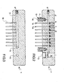
- the washer illustrated in the drawings comprises a manifold in the form of a block 1 comprising two internal longitudinally extending channels, viz. a liquid supply channel 2 and a suction channel 3.
- the liquid supply channel 2 is at one end connected with a bore 4 having provided therein a valve which will be described below.
- the opposite end of the liquid supply channel 2 is closed by a screw 5 having an external thread corresponding to an internal thread in said channel.
- the block 1 comprises 8 channels 6 extending from the top surface of the block 1 through the channel 2 and to the bottom surface of the block and perpendicular to the channel 2.
- each channel 6 located above the channel 2 comprises an internal thread, and a screw 8 having an external thread is screwed into said portion 7.
- a liquid supply pipe 9 extending some distance out from the block 1 is inserted in the lower portion of each channel 6.
- a channel 13 connects the bore 4 with the exterior side of the block 1 and a pipe stub 14 is inserted in said channel 13.
- Another channel 15 connects one end of the suction channel 3 with the exterior side of the block 1, and a pipe stub 16 is inserted in the channel 15.
- the opposite end of the suction channel is closed by a screw 17 having an external thread corresponding to the internal thread of said channel.
- the block 1 further comprises 8 channels extending perpendicularly from the suction channel 3 and each having inserted therein a suction pipe 18 extending a few millimetres longer out from the block 1 than the corresponding liquid supply pipes 9.
- valve body 19 having a lower portion 20 of a greater diametre than the upper portion 21.
- zone between the upper portion 21 and the lower portion 20 of the valve body it comprises a zone 22 of reduced diametre.
- An annular groove in which an O-ring 23 is mounted is provided on the exterior surface of the upper portion 21 of the valve body.
- the underside of the valve body is hollow and the upper end of a coil spring 24 is inserted in said hollow portion.
- the lower end of the coil spring 24 rests on a bottom screw 25 which is screwed into the lower portion of the bore 4 and which is sealed to the block 1 by means of an O-ring 26.
- the lower portion of the bore 4 has a greater diametre than its uppor portion and the lower portion of the valve body 19 cannot move upwardly through the bore 4.
- the block 1 is sealed relative to the lower portion 19 of the valve body by means of an O-ring 27 which is provided in the transition zone between the upper and the lower portion of the bore 4.
Landscapes
- Health & Medical Sciences (AREA)
- Clinical Laboratory Science (AREA)
- Chemical & Material Sciences (AREA)
- Chemical Kinetics & Catalysis (AREA)
- Automatic Analysis And Handling Materials Therefor (AREA)
- Electrical Discharge Machining, Electrochemical Machining, And Combined Machining (AREA)
- Washing And Drying Of Tableware (AREA)
- Laminated Bodies (AREA)
- Bolts, Nuts, And Washers (AREA)
- Electric Stoves And Ranges (AREA)
- Baking, Grill, Roasting (AREA)
- Cleaning By Liquid Or Steam (AREA)
- Paper (AREA)
- Water Treatment By Sorption (AREA)
- Telephone Function (AREA)
Priority Applications (1)
| Application Number | Priority Date | Filing Date | Title |
|---|---|---|---|
| AT82110470T ATE20196T1 (de) | 1981-11-13 | 1982-11-12 | Handbetaetigter wascher fuer mehrlochplatten. |
Applications Claiming Priority (2)
| Application Number | Priority Date | Filing Date | Title |
|---|---|---|---|
| DK503381A DK147254B (da) | 1981-11-13 | 1981-11-13 | Manuelt betjeneligt skylleapparat til skylning af broende i en mikrotestplade |
| DK5033/81 | 1981-11-13 |
Publications (2)
| Publication Number | Publication Date |
|---|---|
| EP0080134A1 true EP0080134A1 (de) | 1983-06-01 |
| EP0080134B1 EP0080134B1 (de) | 1986-06-04 |
Family
ID=8138846
Family Applications (1)
| Application Number | Title | Priority Date | Filing Date |
|---|---|---|---|
| EP82110470A Expired EP0080134B1 (de) | 1981-11-13 | 1982-11-12 | Handbetätigter Wascher für Mehrlochplatten |
Country Status (7)
| Country | Link |
|---|---|
| EP (1) | EP0080134B1 (de) |
| JP (1) | JPS5892486A (de) |
| AT (1) | ATE20196T1 (de) |
| CA (1) | CA1181319A (de) |
| DE (1) | DE3271585D1 (de) |
| DK (1) | DK147254B (de) |
| NO (1) | NO151919B (de) |
Cited By (4)
| Publication number | Priority date | Publication date | Assignee | Title |
|---|---|---|---|---|
| WO1987001616A1 (en) * | 1985-09-16 | 1987-03-26 | Flow Laboratories Limited | Multi-cavity washing apparatus |
| US4879242A (en) * | 1986-11-18 | 1989-11-07 | Yasunobu Tsukioka | Method of syringing reaction bead in examination of blood or the like and apparatus thereof |
| US5620894A (en) * | 1995-06-16 | 1997-04-15 | Glaxo Wellcome Inc. | Apparatus for automated biological cell harvesting |
| EP3187855A4 (de) * | 2014-08-29 | 2018-04-25 | Hitachi High-Technologies Corporation | Reaktionszelle für automatische analysevorrichtung, mit besagter reaktionszelle ausgestattete, automatische analysevorrichtung und analyseverfahren mit verwendung der besagten automatischen analysevorrichtung |
Families Citing this family (1)
| Publication number | Priority date | Publication date | Assignee | Title |
|---|---|---|---|---|
| KR20020015351A (ko) | 1999-06-18 | 2002-02-27 | 고구치 유죠 | 로터리식 실린더장치 |
Citations (4)
| Publication number | Priority date | Publication date | Assignee | Title |
|---|---|---|---|---|
| FR2351405A1 (fr) * | 1976-05-13 | 1977-12-09 | Secr Social Service Brit | Procede et appareil de controle de la proprete d'une cuvette |
| FR2358206A1 (fr) * | 1976-07-16 | 1978-02-10 | Dynatech Worldmed | Procede et dispositif pour le nettoyage de plaques de micro-test |
| DE3028746A1 (de) * | 1980-07-29 | 1982-02-11 | Guido 7919 Bellenberg Oberdorfer | Steuer- und druckventil fuer eine hochdruck-reinigungsanlage |
| DE3029440A1 (de) * | 1980-08-02 | 1982-02-18 | Ernst 4030 Ratingen Fooke | Vorrichtung zum waschen von festkoerpern |
-
1981
- 1981-11-13 DK DK503381A patent/DK147254B/da not_active Application Discontinuation
-
1982
- 1982-07-02 NO NO822317A patent/NO151919B/no unknown
- 1982-11-12 AT AT82110470T patent/ATE20196T1/de active
- 1982-11-12 DE DE8282110470T patent/DE3271585D1/de not_active Expired
- 1982-11-12 JP JP57198787A patent/JPS5892486A/ja active Pending
- 1982-11-12 CA CA000415477A patent/CA1181319A/en not_active Expired
- 1982-11-12 EP EP82110470A patent/EP0080134B1/de not_active Expired
Patent Citations (4)
| Publication number | Priority date | Publication date | Assignee | Title |
|---|---|---|---|---|
| FR2351405A1 (fr) * | 1976-05-13 | 1977-12-09 | Secr Social Service Brit | Procede et appareil de controle de la proprete d'une cuvette |
| FR2358206A1 (fr) * | 1976-07-16 | 1978-02-10 | Dynatech Worldmed | Procede et dispositif pour le nettoyage de plaques de micro-test |
| DE3028746A1 (de) * | 1980-07-29 | 1982-02-11 | Guido 7919 Bellenberg Oberdorfer | Steuer- und druckventil fuer eine hochdruck-reinigungsanlage |
| DE3029440A1 (de) * | 1980-08-02 | 1982-02-18 | Ernst 4030 Ratingen Fooke | Vorrichtung zum waschen von festkoerpern |
Cited By (4)
| Publication number | Priority date | Publication date | Assignee | Title |
|---|---|---|---|---|
| WO1987001616A1 (en) * | 1985-09-16 | 1987-03-26 | Flow Laboratories Limited | Multi-cavity washing apparatus |
| US4879242A (en) * | 1986-11-18 | 1989-11-07 | Yasunobu Tsukioka | Method of syringing reaction bead in examination of blood or the like and apparatus thereof |
| US5620894A (en) * | 1995-06-16 | 1997-04-15 | Glaxo Wellcome Inc. | Apparatus for automated biological cell harvesting |
| EP3187855A4 (de) * | 2014-08-29 | 2018-04-25 | Hitachi High-Technologies Corporation | Reaktionszelle für automatische analysevorrichtung, mit besagter reaktionszelle ausgestattete, automatische analysevorrichtung und analyseverfahren mit verwendung der besagten automatischen analysevorrichtung |
Also Published As
| Publication number | Publication date |
|---|---|
| DK147254B (da) | 1984-05-28 |
| DK503381A (da) | 1983-05-14 |
| EP0080134B1 (de) | 1986-06-04 |
| ATE20196T1 (de) | 1986-06-15 |
| DE3271585D1 (en) | 1986-07-10 |
| CA1181319A (en) | 1985-01-22 |
| NO822317L (no) | 1983-05-16 |
| NO151919B (no) | 1985-03-25 |
| JPS5892486A (ja) | 1983-06-01 |
Similar Documents
| Publication | Publication Date | Title |
|---|---|---|
| US4879431A (en) | Tubeless cell harvester | |
| CA1159394A (en) | Device for electrolytic surface treatment of mechanical workpieces | |
| US4493896A (en) | Dual chamber microplate washer | |
| KR20020064164A (ko) | 액체이송기와 반응용기 | |
| EP0080134A1 (de) | Handbetätigter Wascher für Mehrlochplatten | |
| GB1166287A (en) | Multiple Aperture Fittings for Particle Analyzing Apparatus. | |
| DE2011239B2 (de) | Vorrichtung zum Übertragen von Flüssigkeit in Aufnahmebehälter | |
| EP0545560B1 (de) | Probenentnahmeventil | |
| GB1601026A (en) | Sampling device | |
| US4496657A (en) | Microplate washer | |
| US4860793A (en) | Mixing valve | |
| DE137581T1 (de) | Auftragepistole fuer thermoplastisches material mit eingebautem filter und ventil zur durchflussregelung. | |
| ATE176775T1 (de) | Vorrichtung zum verbinden eines zuführrohres und eines rücklaufrohres an einen flüssigkeitsbehälter | |
| CN219180425U (zh) | 基于液位感应的控制装置及液体箱 | |
| EP1099480B1 (de) | Mikrodosiersystem für die Freistrahldosierung von Flüssigkeiten | |
| DE1782136C3 (de) | Vorrichtung zum Reinigen von Rohrleitungen, insbesondere Bierleitungen | |
| ATE45276T1 (de) | Vorrichtung zum regeln der abgabe einer fluessigkeit aus einem behaelter. | |
| US7270789B1 (en) | Pipettor head having standpipes open at their tops to a pressure/vacuum chamber and method | |
| US4385217A (en) | Flushable manifold for diaphragm protected components | |
| ATE66898T1 (de) | Vorrichtung zum abgeben von fluessigkeiten. | |
| DK178081A (da) | Fremgangsmaade og apparat til indfoering af doserede vaeskevolu7ener i en beholder under tryk | |
| US2646856A (en) | Multiple oiler | |
| DE3606747C2 (de) | ||
| US2244292A (en) | Meter cleaner | |
| CN223960263U (zh) | 一种试管清洗装置 |
Legal Events
| Date | Code | Title | Description |
|---|---|---|---|
| PUAI | Public reference made under article 153(3) epc to a published international application that has entered the european phase |
Free format text: ORIGINAL CODE: 0009012 |
|
| AK | Designated contracting states |
Designated state(s): AT BE CH DE FR GB IT LI LU NL SE |
|
| 17P | Request for examination filed |
Effective date: 19831109 |
|
| ITF | It: translation for a ep patent filed | ||
| GRAA | (expected) grant |
Free format text: ORIGINAL CODE: 0009210 |
|
| AK | Designated contracting states |
Kind code of ref document: B1 Designated state(s): AT BE CH DE FR GB IT LI LU NL SE |
|
| PG25 | Lapsed in a contracting state [announced via postgrant information from national office to epo] |
Ref country code: AT Effective date: 19860604 |
|
| REF | Corresponds to: |
Ref document number: 20196 Country of ref document: AT Date of ref document: 19860615 Kind code of ref document: T |
|
| REF | Corresponds to: |
Ref document number: 3271585 Country of ref document: DE Date of ref document: 19860710 |
|
| ET | Fr: translation filed | ||
| PG25 | Lapsed in a contracting state [announced via postgrant information from national office to epo] |
Ref country code: LU Free format text: LAPSE BECAUSE OF NON-PAYMENT OF DUE FEES Effective date: 19861130 |
|
| PLBI | Opposition filed |
Free format text: ORIGINAL CODE: 0009260 |
|
| 26 | Opposition filed |
Opponent name: FLOW LABORATORIES LIMITED Effective date: 19870304 |
|
| NLR1 | Nl: opposition has been filed with the epo |
Opponent name: FLOW LABORATORIES LIMITED |
|
| PGFP | Annual fee paid to national office [announced via postgrant information from national office to epo] |
Ref country code: NL Payment date: 19871130 Year of fee payment: 6 |
|
| PLAB | Opposition data, opponent's data or that of the opponent's representative modified |
Free format text: ORIGINAL CODE: 0009299OPPO |
|
| R26 | Opposition filed (corrected) |
Opponent name: FLOW LABORATORIES LIMITED Effective date: 19870304 |
|
| PG25 | Lapsed in a contracting state [announced via postgrant information from national office to epo] |
Ref country code: GB Effective date: 19881112 |
|
| PG25 | Lapsed in a contracting state [announced via postgrant information from national office to epo] |
Ref country code: SE Effective date: 19881113 |
|
| PG25 | Lapsed in a contracting state [announced via postgrant information from national office to epo] |
Ref country code: LI Effective date: 19881130 Ref country code: CH Effective date: 19881130 Ref country code: BE Effective date: 19881130 |
|
| BERE | Be: lapsed |
Owner name: A/S NUNC Effective date: 19881130 |
|
| PG25 | Lapsed in a contracting state [announced via postgrant information from national office to epo] |
Ref country code: NL Effective date: 19890601 |
|
| NLV4 | Nl: lapsed or anulled due to non-payment of the annual fee | ||
| PLBM | Termination of opposition procedure: date of legal effect published |
Free format text: ORIGINAL CODE: 0009276 |
|
| STAA | Information on the status of an ep patent application or granted ep patent |
Free format text: STATUS: OPPOSITION PROCEDURE CLOSED |
|
| GBPC | Gb: european patent ceased through non-payment of renewal fee | ||
| PG25 | Lapsed in a contracting state [announced via postgrant information from national office to epo] |
Ref country code: FR Free format text: LAPSE BECAUSE OF NON-PAYMENT OF DUE FEES Effective date: 19890731 |
|
| REG | Reference to a national code |
Ref country code: CH Ref legal event code: PL |
|
| PG25 | Lapsed in a contracting state [announced via postgrant information from national office to epo] |
Ref country code: DE Effective date: 19890801 |
|
| 27C | Opposition proceedings terminated |
Effective date: 19890320 |
|
| REG | Reference to a national code |
Ref country code: FR Ref legal event code: ST |
|
| EUG | Se: european patent has lapsed |
Ref document number: 82110470.0 Effective date: 19890726 |
|
| PLAB | Opposition data, opponent's data or that of the opponent's representative modified |
Free format text: ORIGINAL CODE: 0009299OPPO |