EP0080161A2 - Wärmetauscher - Google Patents
Wärmetauscher Download PDFInfo
- Publication number
- EP0080161A2 EP0080161A2 EP82110610A EP82110610A EP0080161A2 EP 0080161 A2 EP0080161 A2 EP 0080161A2 EP 82110610 A EP82110610 A EP 82110610A EP 82110610 A EP82110610 A EP 82110610A EP 0080161 A2 EP0080161 A2 EP 0080161A2
- Authority
- EP
- European Patent Office
- Prior art keywords
- chamber
- columnar body
- wall
- pipes
- heat exchanger
- Prior art date
- Legal status (The legal status is an assumption and is not a legal conclusion. Google has not performed a legal analysis and makes no representation as to the accuracy of the status listed.)
- Withdrawn
Links
- 239000012530 fluid Substances 0.000 claims abstract description 12
- 238000010438 heat treatment Methods 0.000 claims description 10
- XLYOFNOQVPJJNP-UHFFFAOYSA-N water Substances O XLYOFNOQVPJJNP-UHFFFAOYSA-N 0.000 description 17
- 239000000463 material Substances 0.000 description 6
- 229910045601 alloy Inorganic materials 0.000 description 5
- 239000000956 alloy Substances 0.000 description 5
- XEEYBQQBJWHFJM-UHFFFAOYSA-N Iron Chemical compound [Fe] XEEYBQQBJWHFJM-UHFFFAOYSA-N 0.000 description 4
- RYGMFSIKBFXOCR-UHFFFAOYSA-N Copper Chemical compound [Cu] RYGMFSIKBFXOCR-UHFFFAOYSA-N 0.000 description 3
- 229910052802 copper Inorganic materials 0.000 description 3
- 239000010949 copper Substances 0.000 description 3
- ATUOYWHBWRKTHZ-UHFFFAOYSA-N Propane Chemical compound CCC ATUOYWHBWRKTHZ-UHFFFAOYSA-N 0.000 description 2
- 230000007797 corrosion Effects 0.000 description 2
- 238000005260 corrosion Methods 0.000 description 2
- 229910052742 iron Inorganic materials 0.000 description 2
- 229910052751 metal Inorganic materials 0.000 description 2
- 239000002184 metal Substances 0.000 description 2
- 229910052750 molybdenum Inorganic materials 0.000 description 2
- 229910052758 niobium Inorganic materials 0.000 description 2
- 229910052715 tantalum Inorganic materials 0.000 description 2
- 229910052719 titanium Inorganic materials 0.000 description 2
- 238000003466 welding Methods 0.000 description 2
- 229910052726 zirconium Inorganic materials 0.000 description 2
- 229910000838 Al alloy Inorganic materials 0.000 description 1
- 229910000881 Cu alloy Inorganic materials 0.000 description 1
- 229910000640 Fe alloy Inorganic materials 0.000 description 1
- 229910052782 aluminium Inorganic materials 0.000 description 1
- XAGFODPZIPBFFR-UHFFFAOYSA-N aluminium Chemical compound [Al] XAGFODPZIPBFFR-UHFFFAOYSA-N 0.000 description 1
- 238000002485 combustion reaction Methods 0.000 description 1
- 238000010276 construction Methods 0.000 description 1
- 150000002739 metals Chemical class 0.000 description 1
- 239000001294 propane Substances 0.000 description 1
- 239000010935 stainless steel Substances 0.000 description 1
- 229910001220 stainless steel Inorganic materials 0.000 description 1
- 239000008399 tap water Substances 0.000 description 1
- 235000020679 tap water Nutrition 0.000 description 1
- 238000004804 winding Methods 0.000 description 1
Images


Classifications
-
- F—MECHANICAL ENGINEERING; LIGHTING; HEATING; WEAPONS; BLASTING
- F24—HEATING; RANGES; VENTILATING
- F24H—FLUID HEATERS, e.g. WATER OR AIR HEATERS, HAVING HEAT-GENERATING MEANS, e.g. HEAT PUMPS, IN GENERAL
- F24H1/00—Water heaters, e.g. boilers, continuous-flow heaters or water-storage heaters
- F24H1/10—Continuous-flow heaters, i.e. heaters in which heat is generated only while the water is flowing, e.g. with direct contact of the water with the heating medium
- F24H1/12—Continuous-flow heaters, i.e. heaters in which heat is generated only while the water is flowing, e.g. with direct contact of the water with the heating medium in which the water is kept separate from the heating medium
- F24H1/14—Continuous-flow heaters, i.e. heaters in which heat is generated only while the water is flowing, e.g. with direct contact of the water with the heating medium in which the water is kept separate from the heating medium by tubes, e.g. bent in serpentine form
- F24H1/16—Continuous-flow heaters, i.e. heaters in which heat is generated only while the water is flowing, e.g. with direct contact of the water with the heating medium in which the water is kept separate from the heating medium by tubes, e.g. bent in serpentine form helically or spirally coiled
- F24H1/165—Continuous-flow heaters, i.e. heaters in which heat is generated only while the water is flowing, e.g. with direct contact of the water with the heating medium in which the water is kept separate from the heating medium by tubes, e.g. bent in serpentine form helically or spirally coiled using fluid fuel
-
- F—MECHANICAL ENGINEERING; LIGHTING; HEATING; WEAPONS; BLASTING
- F24—HEATING; RANGES; VENTILATING
- F24H—FLUID HEATERS, e.g. WATER OR AIR HEATERS, HAVING HEAT-GENERATING MEANS, e.g. HEAT PUMPS, IN GENERAL
- F24H1/00—Water heaters, e.g. boilers, continuous-flow heaters or water-storage heaters
- F24H1/22—Water heaters other than continuous-flow or water-storage heaters, e.g. water heaters for central heating
- F24H1/40—Water heaters other than continuous-flow or water-storage heaters, e.g. water heaters for central heating with water tube or tubes
- F24H1/43—Water heaters other than continuous-flow or water-storage heaters, e.g. water heaters for central heating with water tube or tubes helically or spirally coiled
-
- F—MECHANICAL ENGINEERING; LIGHTING; HEATING; WEAPONS; BLASTING
- F28—HEAT EXCHANGE IN GENERAL
- F28D—HEAT-EXCHANGE APPARATUS, NOT PROVIDED FOR IN ANOTHER SUBCLASS, IN WHICH THE HEAT-EXCHANGE MEDIA DO NOT COME INTO DIRECT CONTACT
- F28D7/00—Heat-exchange apparatus having stationary tubular conduit assemblies for both heat-exchange media, the media being in contact with different sides of a conduit wall
- F28D7/02—Heat-exchange apparatus having stationary tubular conduit assemblies for both heat-exchange media, the media being in contact with different sides of a conduit wall the conduits being helically coiled
-
- F—MECHANICAL ENGINEERING; LIGHTING; HEATING; WEAPONS; BLASTING
- F28—HEAT EXCHANGE IN GENERAL
- F28D—HEAT-EXCHANGE APPARATUS, NOT PROVIDED FOR IN ANOTHER SUBCLASS, IN WHICH THE HEAT-EXCHANGE MEDIA DO NOT COME INTO DIRECT CONTACT
- F28D7/00—Heat-exchange apparatus having stationary tubular conduit assemblies for both heat-exchange media, the media being in contact with different sides of a conduit wall
- F28D7/04—Heat-exchange apparatus having stationary tubular conduit assemblies for both heat-exchange media, the media being in contact with different sides of a conduit wall the conduits being spirally coiled
Definitions
- the present invention relates to a heat exchanger. More particularly, it relates to a heat exchanger of light weight having high heat exchange efficiency.
- heat exchangers used in water heaters are made of copper or its alloy, which has good heat conductivity and provides high heat exchange efficiency. Since, however, copper and its alloy are apt to be corroded on combustion of urban gas or propane gas, the heat exchangers require to have thick walls. This makes the heat exchangers heavier.
- the main object of the present invention provides a heat exchanger of light weight, which has good heat exchange efficiency.
- the heat exchanger of the invention comprises a chamber having an inlet and an outlet, a columnar body positioned vertically in the center of the chamber and a plurality of pipes surrounding spirally the columnar body and supported by a plurality of supports provided on the outer wall of the columnar body and projected outwardly or on the inner wall of the chamber and projected inwardly, said pipes being arranged side by side at substantially a horizontal position between the outer wall of the columnar body and the inner wall of the chamber.
- the characteristic feature of the heat exchanger of the invention resides in having a plurality of pipes for a fluid surrounding spirally a columnar body in the space between the inner wall of a chamber and the outer wall of the columnar body located vertically at the center of the chamber, said pipes being arranged side by side at substantially a horizontal position, to let flow a fluid spirally along the columnar body in contact with the outer surfaces of the pipes.
- the heat exchanger of the invention comprises as the essential elements a chamber, a columnar body, supports and pipes.
- the chamber and the columnar body may be made of same or different materials but are preferably made of a same material.
- the materials may be any one insofar as they are resistant to heat and corrosion. Specific examples are iron, iron alloy, stainless steel, aluminum, aluminum alloy, copper, copper alloy, etc. Other anti-corrosive metals such as Ti, Zr, Ta, Mo and Nb, and their alloys are also usable.
- the chamber is provided with an inlet and an outlet, which may be used respectively for introduction and discharge of a fluid for heating or to be heated.
- the columnar body may be constructed, for instance, in a shape of cylindrical or square pipe optionally closed at both ends or of column or square pillar optionally provided with a hollow at the center. In general, the use of a hollow columnar body closed at both ends is preferred for making the weight of the heat exchanger light and saving the apparatus cost. When the columnar body is hollow and opened at both ends, any fluid for heating or to be heated may flow therein.
- the supports and the pipes may be also made of same or different materials. Examples of the usable material are substantially the same as explained for the chamber and the columnar body.
- the supports which may be shaped, for instance, in a bar-like or open-sided square form, are fixed to the outer wall of the columnar body or the inner wall of the chamber by any conventional means (e.g. welding). In view of their purpose to support the pipes, the number and position of the supports may be suitably chosen.
- the pipes may be constructed in a single structure or in a double structure. When constructed in a double structure, the inside of each pipe may be made of a corrosion-resistant metal such as Ti, Zr, Ta, Mo and Nb and their alloys and the outside made of iron or its alloy.
- the pipes are spirally wound around the columnar body and arranged side by side at substantially a horizontal position. They are closely contacted each other.. The larger number of spiral winding affords a better result and may be suitably selected taking heat exchange rate, strength of material, etc. into consideration.
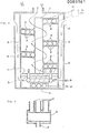
- the columnar body 1 is provided with supports 3,.3, Vietnamese positions by welding.
- a pair of supports 3 and-3 form a space of open-sided square shape in section, and the space holds pipes 2, 2 and 2, which surround spirally the columnar body 1 and are arranged side by side at substantially a horizontal position.
- the number and sectional shape of the pipes are optional.
- the number and form of the supports are also optional.
- the columnar body 1 is constructed in a hollow column closed at the upper and lower ends and placed vertically at the center of the chamber 5 on the bottom plate 7.
- the pipes 2, 2 and 2 are held and arranged in a closely contacted relationship, and also the utmost inside pipe and the utmost outside pipe are respectively kept in close contact with the outer wall of the columnar body 1 and the inner wall of the chamber 5, whereby a spiral passage is formed between the outer wall of the columnar body 1 and the inner wall of the chamber 5.
- the chamber 5 has an outer shell 6 to make a passage.
- tap water (W) is supplied from a valve through the pipe (P) to the water feeding section 4. Then, the water flows into the pipes 2, 2 and 2, goes up spirally and reaches to the water discharge section 11.
- combustible gas (G) is ignited at the gas burner 8 so that heating gas goes up spirally along the columnar body 1 as indicated by the arrow line and is discharged from the outlet 10.
- air is introduced from the inlet 9, it can be pre-heated during the flowing through the passage between the chamber 5 and the outer shell 6 so that the heating gas is able to obtain a higher temperature.
- Heat exchange is effected between the water flowing in the pipes and the heating gas flowing in the chamber. As the result, the heating gas is cooled to a lower temperature such as about 50°C and discharged from the outlet 10, while the water (H) is heated to a higher temperature such as about 80 to 90°C and taken out from the water discharge section 11.
- Fig. 5 shows another example of a water heater incorporated with the heat exchanger of the invention wherein the supports 3, 3, Vietnamese are fixed not to the outer wall of the columnar body 1 but to the inner wall of the chamber 5. Further, the chamber 5 is not provided with an outer shell so that air is not pre-heated. Heating of water may be effected in the same manner as in the water heater shown in Fig. 3.
- the heat exchanger of the invention is extremely large in the contact area between heating gas and the pipes, through which a fluid to be heated flows, so that the fluid can be efficiently heated.
- the heat exchanger has a high heat exchange rate.
Landscapes
- Engineering & Computer Science (AREA)
- Physics & Mathematics (AREA)
- Thermal Sciences (AREA)
- Mechanical Engineering (AREA)
- General Engineering & Computer Science (AREA)
- Chemical & Material Sciences (AREA)
- Combustion & Propulsion (AREA)
- Heat-Exchange Devices With Radiators And Conduit Assemblies (AREA)
Applications Claiming Priority (2)
| Application Number | Priority Date | Filing Date | Title |
|---|---|---|---|
| JP18577681A JPS5886387A (ja) | 1981-11-19 | 1981-11-19 | 熱交換器 |
| JP185776/81 | 1981-11-19 |
Publications (2)
| Publication Number | Publication Date |
|---|---|
| EP0080161A2 true EP0080161A2 (de) | 1983-06-01 |
| EP0080161A3 EP0080161A3 (de) | 1983-11-30 |
Family
ID=16176685
Family Applications (1)
| Application Number | Title | Priority Date | Filing Date |
|---|---|---|---|
| EP82110610A Withdrawn EP0080161A3 (de) | 1981-11-19 | 1982-11-18 | Wärmetauscher |
Country Status (3)
| Country | Link |
|---|---|
| EP (1) | EP0080161A3 (de) |
| JP (1) | JPS5886387A (de) |
| AU (1) | AU9062782A (de) |
Cited By (9)
| Publication number | Priority date | Publication date | Assignee | Title |
|---|---|---|---|---|
| WO1988001362A1 (fr) * | 1986-08-21 | 1988-02-25 | Emil Bader | Echangeur de chaleur a contre-courant a faisceau helicoidal de tubes |
| DE3925795A1 (de) * | 1989-08-04 | 1991-02-07 | Walter Englmann | Spiralrohr-waermetauscher |
| AT392839B (de) * | 1988-10-21 | 1991-06-25 | Vaillant Gmbh | Durchlaufwaermetauscher |
| WO2001055661A1 (fr) * | 2000-01-26 | 2001-08-02 | Huai Yin Hui Huang Tai Yang Neng You Xian Gong Si | Echangeur thermique a gaine en spirale assemblee |
| WO2011010280A1 (en) * | 2009-07-20 | 2011-01-27 | Yun Keung To | Food steamer and steam heat energy collector |
| CN109405589A (zh) * | 2018-11-30 | 2019-03-01 | 华南理工大学 | 一种双管程独立换热的球形换热器 |
| EP3502214A1 (de) * | 2017-12-22 | 2019-06-26 | Axens | Wärmetauscherspule für die hydrobehandlung oder hydroumwandlung |
| EP3502213A1 (de) * | 2017-12-22 | 2019-06-26 | Axens | Wärmetauscherspule für die hydrobehandlung oder hydroumwandlung |
| DE10234238B4 (de) * | 2001-07-25 | 2020-09-17 | Vaillant Gmbh | Wärmetauscher |
Family Cites Families (8)
| Publication number | Priority date | Publication date | Assignee | Title |
|---|---|---|---|---|
| BE422424A (de) * | ||||
| US1893484A (en) * | 1932-07-26 | 1933-01-10 | Joseph S Belt | Heat exchanger |
| FR2155770A1 (en) * | 1971-10-04 | 1973-05-25 | Ind Chauffage | Spiral tube heat exchanger - with tubes contacting shell to define shell-side flow |
| JPS5169250A (en) * | 1974-12-12 | 1976-06-15 | Eiichi Uratani | Rasenryuronoaru netsukookanki |
| JPS53900A (en) * | 1976-06-25 | 1978-01-07 | Hitachi Metals Ltd | Method of manufacturing matrix magnet |
| FR2447528A1 (fr) * | 1979-01-23 | 1980-08-22 | Zundel Daniel | Echangeur de chaleur a tuyaux |
| FR2482717A1 (fr) * | 1980-05-14 | 1981-11-20 | Psa | Echangeur de temperature a tubes parcourus en parallele par un fluide primaire |
| FR2501832A1 (fr) * | 1981-03-13 | 1982-09-17 | Bonneville Simone | Epurateur - echangeur thermique pour gaz de combustion |
-
1981
- 1981-11-19 JP JP18577681A patent/JPS5886387A/ja active Pending
-
1982
- 1982-11-16 AU AU90627/82A patent/AU9062782A/en not_active Abandoned
- 1982-11-18 EP EP82110610A patent/EP0080161A3/de not_active Withdrawn
Cited By (10)
| Publication number | Priority date | Publication date | Assignee | Title |
|---|---|---|---|---|
| WO1988001362A1 (fr) * | 1986-08-21 | 1988-02-25 | Emil Bader | Echangeur de chaleur a contre-courant a faisceau helicoidal de tubes |
| AT392839B (de) * | 1988-10-21 | 1991-06-25 | Vaillant Gmbh | Durchlaufwaermetauscher |
| DE3925795A1 (de) * | 1989-08-04 | 1991-02-07 | Walter Englmann | Spiralrohr-waermetauscher |
| WO2001055661A1 (fr) * | 2000-01-26 | 2001-08-02 | Huai Yin Hui Huang Tai Yang Neng You Xian Gong Si | Echangeur thermique a gaine en spirale assemblee |
| DE10234238B4 (de) * | 2001-07-25 | 2020-09-17 | Vaillant Gmbh | Wärmetauscher |
| WO2011010280A1 (en) * | 2009-07-20 | 2011-01-27 | Yun Keung To | Food steamer and steam heat energy collector |
| EP3502214A1 (de) * | 2017-12-22 | 2019-06-26 | Axens | Wärmetauscherspule für die hydrobehandlung oder hydroumwandlung |
| EP3502213A1 (de) * | 2017-12-22 | 2019-06-26 | Axens | Wärmetauscherspule für die hydrobehandlung oder hydroumwandlung |
| CN109405589A (zh) * | 2018-11-30 | 2019-03-01 | 华南理工大学 | 一种双管程独立换热的球形换热器 |
| CN109405589B (zh) * | 2018-11-30 | 2023-10-27 | 华南理工大学 | 一种双管程独立换热的球形换热器 |
Also Published As
| Publication number | Publication date |
|---|---|
| EP0080161A3 (de) | 1983-11-30 |
| AU9062782A (en) | 1983-06-16 |
| JPS5886387A (ja) | 1983-05-23 |
Similar Documents
| Publication | Publication Date | Title |
|---|---|---|
| US5579836A (en) | Heat-exchanger coil assembly and complex thereof | |
| US5228413A (en) | Multiple boiler | |
| US4271789A (en) | Energy conversion system | |
| KR100879189B1 (ko) | 이중 튜브 번들을 갖는 응축 열교환기 | |
| EP0141825B1 (de) | Wärmeaustauscher | |
| EP0080161A2 (de) | Wärmetauscher | |
| US3373802A (en) | Heat exchanger with removable tube groups of decreasing flow area | |
| JPS59500982A (ja) | 温水、熱湯または蒸気発生用のガス加熱また石油加熱ボイラ | |
| EP0553238B1 (de) | Spiralenförmiger wärmetauscher | |
| NO125510B (de) | ||
| EP0055737A1 (de) | Wärmeaustauscher für fliessende massen | |
| JPS62272062A (ja) | ガス湯沸かし器の加熱体部 | |
| US4867234A (en) | Heat exchanger | |
| US3930537A (en) | Heat exchanger | |
| RU2182679C2 (ru) | Подогреватель жидких и газообразных сред | |
| JPS58108388A (ja) | 熱交換器 | |
| WO2003021177A1 (en) | Piping system and method of making the same and associated method of heat transfer | |
| WO1991014906A1 (en) | A heat-storing body of metal and a heat storage means | |
| US12546510B2 (en) | Heat exchanger for heating devices, and tube-assembly module for a heat exchanger | |
| JPH0245785B2 (de) | ||
| JPS5886388A (ja) | 熱交換器 | |
| JPH0566517B2 (de) | ||
| JPS58115298A (ja) | 熱交換器 | |
| US1069372A (en) | Apparatus for heating water and other liquids or fluids. | |
| JPH0214629B2 (de) |
Legal Events
| Date | Code | Title | Description |
|---|---|---|---|
| PUAI | Public reference made under article 153(3) epc to a published international application that has entered the european phase |
Free format text: ORIGINAL CODE: 0009012 |
|
| 17P | Request for examination filed |
Effective date: 19821118 |
|
| AK | Designated contracting states |
Designated state(s): DE FR GB IT NL |
|
| PUAL | Search report despatched |
Free format text: ORIGINAL CODE: 0009013 |
|
| STAA | Information on the status of an ep patent application or granted ep patent |
Free format text: STATUS: THE APPLICATION HAS BEEN WITHDRAWN |
|
| AK | Designated contracting states |
Designated state(s): DE FR GB IT NL |
|
| 18W | Application withdrawn |
Withdrawal date: 19831029 |