EP0080374A2 - Verfahren und Gerät zum Messen der Ist-Position in einem Positionierungssystem - Google Patents
Verfahren und Gerät zum Messen der Ist-Position in einem Positionierungssystem Download PDFInfo
- Publication number
- EP0080374A2 EP0080374A2 EP82306249A EP82306249A EP0080374A2 EP 0080374 A2 EP0080374 A2 EP 0080374A2 EP 82306249 A EP82306249 A EP 82306249A EP 82306249 A EP82306249 A EP 82306249A EP 0080374 A2 EP0080374 A2 EP 0080374A2
- Authority
- EP
- European Patent Office
- Prior art keywords
- control device
- error
- storage means
- current position
- control
- Prior art date
- Legal status (The legal status is an assumption and is not a legal conclusion. Google has not performed a legal analysis and makes no representation as to the accuracy of the status listed.)
- Granted
Links
Images

Classifications
-
- G—PHYSICS
- G05—CONTROLLING; REGULATING
- G05B—CONTROL OR REGULATING SYSTEMS IN GENERAL; FUNCTIONAL ELEMENTS OF SUCH SYSTEMS; MONITORING OR TESTING ARRANGEMENTS FOR SUCH SYSTEMS OR ELEMENTS
- G05B19/00—Program-control systems
- G05B19/02—Program-control systems electric
- G05B19/18—Numerical control [NC], i.e. automatically operating machines, in particular machine tools, e.g. in a manufacturing environment, so as to execute positioning, movement or co-ordinated operations by means of program data in numerical form
-
- G—PHYSICS
- G05—CONTROLLING; REGULATING
- G05B—CONTROL OR REGULATING SYSTEMS IN GENERAL; FUNCTIONAL ELEMENTS OF SUCH SYSTEMS; MONITORING OR TESTING ARRANGEMENTS FOR SUCH SYSTEMS OR ELEMENTS
- G05B19/00—Program-control systems
- G05B19/02—Program-control systems electric
- G05B19/18—Numerical control [NC], i.e. automatically operating machines, in particular machine tools, e.g. in a manufacturing environment, so as to execute positioning, movement or co-ordinated operations by means of program data in numerical form
- G05B19/19—Numerical control [NC], i.e. automatically operating machines, in particular machine tools, e.g. in a manufacturing environment, so as to execute positioning, movement or co-ordinated operations by means of program data in numerical form characterised by positioning or contouring control systems, e.g. to control position from one programmed point to another or to control movement along a programmed continuous path
- G05B19/21—Numerical control [NC], i.e. automatically operating machines, in particular machine tools, e.g. in a manufacturing environment, so as to execute positioning, movement or co-ordinated operations by means of program data in numerical form characterised by positioning or contouring control systems, e.g. to control position from one programmed point to another or to control movement along a programmed continuous path using an incremental digital measuring device
- G05B19/23—Numerical control [NC], i.e. automatically operating machines, in particular machine tools, e.g. in a manufacturing environment, so as to execute positioning, movement or co-ordinated operations by means of program data in numerical form characterised by positioning or contouring control systems, e.g. to control position from one programmed point to another or to control movement along a programmed continuous path using an incremental digital measuring device for point-to-point control
- G05B19/231—Numerical control [NC], i.e. automatically operating machines, in particular machine tools, e.g. in a manufacturing environment, so as to execute positioning, movement or co-ordinated operations by means of program data in numerical form characterised by positioning or contouring control systems, e.g. to control position from one programmed point to another or to control movement along a programmed continuous path using an incremental digital measuring device for point-to-point control the positional error is used to control continuously the servomotor according to its magnitude
- G05B19/232—Numerical control [NC], i.e. automatically operating machines, in particular machine tools, e.g. in a manufacturing environment, so as to execute positioning, movement or co-ordinated operations by means of program data in numerical form characterised by positioning or contouring control systems, e.g. to control position from one programmed point to another or to control movement along a programmed continuous path using an incremental digital measuring device for point-to-point control the positional error is used to control continuously the servomotor according to its magnitude with speed feedback only
-
- G—PHYSICS
- G05—CONTROLLING; REGULATING
- G05B—CONTROL OR REGULATING SYSTEMS IN GENERAL; FUNCTIONAL ELEMENTS OF SUCH SYSTEMS; MONITORING OR TESTING ARRANGEMENTS FOR SUCH SYSTEMS OR ELEMENTS
- G05B2219/00—Program-control systems
- G05B2219/30—Nc systems
- G05B2219/42—Servomotor, servo controller kind till VSS
- G05B2219/42118—Breaking of control loop, closing open control loop
-
- G—PHYSICS
- G05—CONTROLLING; REGULATING
- G05B—CONTROL OR REGULATING SYSTEMS IN GENERAL; FUNCTIONAL ELEMENTS OF SUCH SYSTEMS; MONITORING OR TESTING ARRANGEMENTS FOR SUCH SYSTEMS OR ELEMENTS
- G05B2219/00—Program-control systems
- G05B2219/30—Nc systems
- G05B2219/50—Machine tool, machine tool null till machine tool work handling
- G05B2219/50167—Adapting to copying
Definitions
- This invention relates to a method / sensing current position in a position control system for controlling the position of a servomotor by means of a plurality of but not necessarily exclusively, control devices. More particularly,/the invention relates to a and apparatus for method / sensing current position in a position control system or reduce so improved as to eliminate/a positional error when switching among a plurality of control devices to drive and control a servomotor.
- a system in which a movable machine element driven by a single servomotor is positionally controlled by placing the servomotor alternatively under the control of a plurality of control devices.
- a movable machine element driven by a single servomotor is positionally controlled by placing the servomotor alternatively under the control of a plurality of control devices.
- the servomotor of the machine tool is positionally controlled by both the numerical control device and tracer control device to machine the workpiece as desired. Accordingly, during the period that the numerical control device is connected to the servomotor to drive the same, no connection exists between the servomotor and the tracer control device. Conversely, during the period that there is a connection between the tracer control device and the servomotor to drive the motor, the numerical control device is severed from the motor.
- the numerical control device and tracer control device each incorporate a current position register to keep track of the current position of the movable machine element driven by the servomotor. Since control of the movable machine element of the machine tool is effected on the basis of the data stored in these registers, it is necessary for the amount of servomotor rotation to be sensed and for the current position registers to be updated based upon such rotation. This is true even for the position register incorporated in whichever of the control devices is not connected to the servomotor during such rotation. To this end, a so-called follow-up control method is available wherein the data stored in the error register of a position control circuit, provided in each of the control devices, is read in order to update the current position register.
- a method of sensing current position in a position control system of the type including first and second control devices each having at least means for generating command pulses, error storage means for computing and storing an error between the number of command pulses and feedback pulses each of which is generated whenever a motor rotates by a predetermined amount, and a current position register, a speed control circuit for driving and controlling the motor on the basis of the error stored in each of said error storage means, and a switching circuit for connecting said first and second control devices to the speed control circuit, wherein the motor is positionally controlled on the basis of the error stored in the error storage means of the control device connected to said speed control circuit by said switching circuit, which method is for updating the data in the current position register of whichever of the first and second control devices is not connected to said speed control circuit, .and for enabling the unconnected control device to sense the current position of a movable element driven by the motor under the control of the connected control device, said method comprising steps of:
- an apparatus for sensing current position in a position control system of the type including first and second control devices each having at least means for generating command pulses, error storage means for computing and storing an error between the number of command pulses and feedback pulses each of which is generated whenever a motor rotates by a predetermined amount, and a current position register, a speed control circuit for driving and controlling the motor on the basis of the error stored in each of said error storage means, and a switching circuit for connecting said first and second control devices to the speed control circuit, wherein the motor is positionally controlled on the basis of the error stored in the error storage means of the control device connected to said speed control circuit by said switching circuit, which apparatus is adapted and arranged to employ, when in use, a method for updating the data in the current position register of whichever of the first and second control devices is not connected to said speed control circuit, and for enabling the unconnected control device to sense the current position of a movable element ' driven by the motor under the control of the connected control device, said method
- Examples of the present invention may provide a method and apparatus for sensing current position in a position control system of the type in which a single servomotor is controlled by a plurality of control devices, which method and apparatus may prevent the accumulation of an error caused by switching among the control devices.
- Examples of the present invention may provide a and apparatus for method / sensing current position in a position control system which prevents the data stored in a current position register from being changed by switching from one control device to another.
- Examples of the present invention may provide and apparatus for a method / sensing current position in a position control system in which accurate positional control is possible even when switching among control devices.
- Examples of the present invention may provide a and apparatus for method / sensing current position in a position control system which prevents a servomotor from being rotated in a direction which will cause an error to accumulate whenever the servomotor is switched from one control device to another.
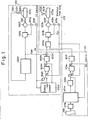
- the NC device 101 includes a paper tape reader 101b for reading a paper tape lOla in which NC data has been punched, and a control unit 101c.
- the control unit 101c causes the tape reader 101b to read in the NC command data from the paper tape lOla, and decodes the read NC data, delivering, e.g., M, S and T function commands to the machine side through a power sequence controller and a move command to a pulse distributor 101d upon initiating an arithmetic operation based on incremental values.
- the control unit 101c controls the updating of a current position register and a so-called remaining movement register, and stores the current position of a movable machine element, such as the table or tool of a machine tool, by executing follow-up control, described later, when the NC device 101 is severed from the servo system.
- the pulse distributor 101d executes well-known pulse distribution computations on the basis of incremental values, and generates distributed pulses (command pulses) P s at a'frequency corresponding to a commanded speed.
- Numeral lOle denotes an error computing and storing unit which computes the difference (error) E r between the number of the input command pulses P s received from the pulse distributor 101d and the number of feedback pulses Ff generated by a pulse coder, as will be described below.
- a digital signal indicative of the error E r is applied to a DA converter 101f for converting the error E r into an analog voltage.
- the block indicated at 103 represents the machine tool side.
- a switching circuit 103a a speed control circuit 103b, including a speed control unit, a servoamplifier unit and the like, which is switched between the NC device 101 and TC device 102 by the switching circuit 103a, a servomotor 103c, a tachometer 103d for generating a voltage indicative of the actual rotational speed of the servomotor 103c, a pulse coder 103e for generating a feedback pulse Fp each time the servomotor rotates by a predetermined amount, a ball screw 103f rotated by the servomotor 103c, a table 103g transported by the ball screw 103f as the ball screw rotates, and a tool 103h for machining a workpiece 103i.
- the NC device 101 is connected to the machine tool side 103 by the switching circuit 103a.
- the pulse distributor 101d executes the pulse distribution computation on the basis of the incremental values and produces the distributed pulses P s which are applied to the error computing and storing unit 101e, the content whereof becomes non-zero as a result.
- the DA converter 101f provides a voltage corresponding to the content of the unit 10le, and the motor 103c is driven by the speed control circuit 103b so as to move the table 103g.
- the feedback pulse Fp is generated by the pulse coder 103e and is applied to the error calculating and storing unit 101e, with the latter storing the difference E between the number of command pulses P and the number of feedback pulses Fp. Thenceforth, servo control is executed in such a manner that the error E r approaches zero, with the table being transported to the target position as machining is carried out.
- the command pulses P s generated by the pulse distributor 101d are also applied to the control unit 101c as the foregoing processing is being executed, the pulses P s serving to update a current position register and a register which stores an amount of movement yet to be executed.
- the TC device 102 includes a model 102a, a sylus 102b in contact with the surface of the model, a tracer head 102c, an analog arithmetic circuit 102d for producing signals indicative of tracer speed components along each axis, based on a displacement signal produced by the stylus 102b, a speed control circuit 102e, a motor 102f, a tachometer 102g for sensing the speed of the motor 102f, a pulse coder 102h for generating a pulse P c each time the motor 102f rotates by a predetermined amount, a ball screw 102i rotated by the motor 102f, a table 102j transported by the ball screw 102d as it rotates, an OR gate 102k, and an error computing and storing unit 102m, comprising a reversible counter, for storing an error E , between the number of pulses (command pulses) P c generated by the pulse coder 102h, and the number of feedback
- the TC device 102 is connected to the servo circuitry on the machine tool side 103 by the switching circuit 103a.
- the stylus 102b is displaced in accordance with the shape of the model 102a and produces a displacement signal which is fed into the analog arithmetic circuit 102d.
- the analog arithmetic circuit 102d produces a signal indicative of the tracer speed components along each axis, these corresponding to the stylus displacement.
- The.signal namely a commanded voltage CAV, causes the motor 102f to rotate further, and also rotates the motor 103c.
- the pulse coders 102h, 103e When the motors 102f, 103c are rotated by a predetermined amount, the pulse coders 102h, 103e generate the command pulse P and the feedback pulse Fp, which enter the error computing and storing unit 102m.
- the content of the unit 102m will be zero if the tracer and machine tool sides are in perfect synchronization, and non-zero when they are not.
- the DA converter 102n produces a voltage commensurate with the content of unit 102m, and the mixing circuit 102n' combines this voltage with the commanded voltage CAV, whereby synchronization is achieved.
- servo control is executed in such a manner that the error voltage E r , produced by the DA converter approaches zero, with the table 103g being made to follow, i.e., to move in synchronization with, the table 102j.
- the command pulses P from the pulse coder 102h are fed into the follow-up circuit 102p to update the content of a current position register incorporated within the circuit.
- the NC device 101 store internally the current position of the machine tool, namely the table 103g, at all times even when tracer control is being carried out owing to a connection between the TC device 102 and machine tool side 103.
- the TC device 102 it is necessary for the TC device 102 to constantly store the current position of the machine tool even when ordinary numerical control is being performed owing to a connection between the NC device 101 and the machine tool.
- the pulse coder 103e produces the feedback pulses FP, each pulse being generated whenever the motor 103c rotates by a predetermined amount.
- the content of the error computing and storing unit 10le of NC device 101 is updated, i.e., decremented by one step in the case of forward rotation, each time a feedback pulse Fp is produced. If we assume that the content of the error computing and storing unit 101e initially is zero, then its content will be decremented to -m l by the generation of m l -number of feedback pulses.
- the -m l data is read by the control unit 101c which performs the operation: with respect to the content M of a current position register located within the control unit lOlc.
- the initial value of M is M o .
- the control unit 102 also changes the sign of the read data from - to +, applying +m 1 to the pulse distributor 101d.
- the pulse distributor 101d responds to the +m 1 data by immediately performing a pulse distribution operation to produce the distributed pulses P s .
- the distributed pulses P s enter the s s the error computing and storing unit 10le, the content thereof being updated by one step in the positive direction each time a pulse P s arrives.
- the error computing and storing unit 101e concurrently receives the feedback pulses Fp at its other input as long as the motor 103c is rotating. These pulses update the unit 10le by one step in the negative direction each time one of them arrives. Accordingly, if we assume that the time at which the content -m 1 is read out of unit lOle is t l , that the time at which the m l -number of distributed pulses P s are generated is t 2 , and that m 2 -number of feedback pulses FP are generated between times t 1 and t 21 then the content of error computing and storing unit 101e at time t 2 will be -m 2 .
- the control unit 101c When a number of distributed pulses P s equivalent to the commanded quantity m 1 have been produced, the control unit 101c generates internally a signal DEN indicative of the end of the pulse distribution operation. The control unit 101c responds to the signal DEN by once again reading the content (-m 2 ) of the unit 10le and performing the following addition: The control unit lOle also applies the data m 2 to the pulse distributor lOld. Owing to the arithmetic operation (1') above, the content M of the current position register becomes m 1 +m 2 +M 0 (where M o is the initial value stored in the current position register prior to follow-up control).
- tl is the time at which the content of error computing and storing unit lOle is initially read
- m i represents the number of feedback pulses produced between time ti-1 and time ti.
- the total number M of feedback pulses FP produced up to time tj+1 may be expressed by the following: which is precisely in agreement with the sum total exhibited by the error computing and storing unit 101e.
- the current position register within the control unit 101c will thus store the current position of the machine tool element at all times in accordance with the follow-up control method.
- Numerals 101g and 102q denote position control circuits, respectively, the former being constituted by the error computing and storing unit 101e and DA converter 101f, the latter by the error computing and storing unit 102m and DA converter 102n.
- the switching circuit 103a selects the desired one of the position control circuits 101g, 102q of the respective control devices 101, 102 and connects it to the speed control circuit 103b so that a workpiece may be machined under tracer control on some occasions and under ordinary numerical control on others.
- the position control circuits 101g, 102q and their peripheral circuits develop an offset voltage.
- the motor 103c will not stop even when the data (error) stored in the error computing and storing unit 101e becomes zero. Instead, the motor will come to rest when the error attains a value of -l 1 .
- the position control circuit 102q of the TC device I02 is connected to the speed control circuit 103b to form a closed loop, the motor 103c will not stop even when the data (error) stored in the error computing and storing unit 102m becomes zero.
- the motor will come to rest when the error attains a value of -l 2 . Consequently, if the abovementioned errors l 1 , l 2 (referred to as steady deviations) are unequal, that is, if the drift values developed in each closed loop differ, then the motor 103c will be rotated by an amount corresponding to the difference from one drift value to the other whenever the machine tool is switched between the control devices. Furthermore, in the disconnected control device whose current position data is updated internally in accordance with the follow-up control technique, an error accumulates since the motor 103c is moved by an amount equivalent to 1 1 or l 2 each time a switch is made, even when command pulses are not applied. Also, the content of the current position register in one of the control devices is updated in increments of (l 1 +l 2 ) with each switching operation, so that there is a change in current position indication in that control device.
- Fig. 3 illustrates movement along one axis only.
- CP 1 indicates the current position stored in the NC device
- MP 1 , MP 2 the machine element position
- CP 2 the current position stored in the TC device
- l 1 , 1 2 the steady deviations of the NC device and TC device, respectively.
- MP 1 , MP 2 for descriptive purposes only, i.e., that MP 1 and MP 2 designate exactly the same point along the axis of movement.
- the machine element position MP 2 is shifted over a distance +1 2 owing to the changeover, since the steady deviation for the TC device 102 is -l 2 .
- the machine element stabilizes and comes to rest at the position MP 2 given by (a+l 1 +l 2 ), as shown in (B) of Fig. 3.
- the pulse coder 103e (Fig. 1) generates l 2 -number of feedback pulses Fp, whereby the contents of the error computing and storing units lOle, 102m (Figs.
- the present invention seek to effect an improvement in a system for driving a servomotor by means of different control devices.
- the improvement is such that no error accumulates because of a changeover from one control device to another, and such that there is no change in current position registered in the control devices owing to the switching operation and, hence, no change in the current position indication.
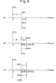
- a method of sensing current position according to the present invention will be described with reference to Fig. 4. present examples of the First, the gist of the/inventive method can be understood by better recogizing the flaw in the prior art. Specifically, when the control devices are switched, the machine element position is shifted by l 1 or l 2 , namely by the steady deviation of the connected control device, and the content of the error computing and storing unit of the disconnected control device becomes -(l 1 +l 2 ). The disconnected control device then has the internally registered current position updated by (l 1 +l 2 ) owing to follow-up control, so that the registered data is brought into agreement with the new machine element position. In addition, the content of the error computing and storing unit is cleared to zero.
- the machine element position MP 2 is shifted over a distance l 2 owing to the changeover, since the steady deviation for the TC device 102 is l 2 .
- the machine element stabilizes and comes to rest at the position MP 2 given by (a+l 1 +l 2 ), as shown in (B) of Fig. 4.
- the pulse coder 103e (Fig. 1) generates l 2 -number of feedback pulses Fp, whereby the contents of the error computing and storing units 10le, 102m (Figs.
- the value stored in the error computing and storing unit 10le is -(l 1 +l 2 ) regardless of the fact that the steady deviation of the NC device is l 1 . Accordingly, as shown by the dashed lines in Fig. 4(C), the machine element position MP 1 moves a distance l 2 , in a direction opposite to that moved in Fig. 4(B), and stops at (a+l 1 ) As a result, l 2 -number of feedback pulses Fp are generated, the content of error computing and storing unit 101e stabilizes at -l 1 , and the content of error computing and storing unit 102m becomes zero.
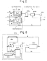
- Numeral 202 denotes a current position register for storing the current position AP.
- Numeral 203 denotes a follow-up arithmetic circuit whose inputs are the content B of the steady deviation register 201, the old current position AP stored in the current position register 202, and the content A of the error computing and storing unit 101e.
- the arithmetic circuit 203 performs the operatio- given by the following expression: to update the current position.
- Numeral 204 denotes an arithmetic circuit for performing the operation: and for applying the result to the pulse distributor 101d.
- the content of the current position register 202 is updated to (AP+m 1 ) in accordance with the foregoing arithmetic operations (1) and (2), and the pulse distributor 101d is issued a command equivalent to m 1 .
- the pulse distributor 101d immediately begins the pulse distribution operation for the production of the distributed pulses P , namely the command pulses.
- These pulses are applied to the error computing and storing unit 101e, incrementing the content thereof one step in the positive (forward) direction each time a distributed pulse P s is generated.
- the pulse distribution end signal is produced and the pulse distribution operation ends, at which time the content of error computing and storing unit 101e is -(l 1 +l 2 ).
- the feedback pulses Fp are applied to the error computing and storing unit 10le while the pulse distribution operation based on m 1 is being executed.
- the feedback pulses update the unit 101e in the negative (reverse) direction as each one is generated.
- the content of the current position register 202 is updated to (AP+m 1 +m 2 ), and a command equivalent to m 2 is applied to the pulse distributor 101d. Thereafter, by exercising control in a similar manner, the content of the current position register 202 will be updated correctly to AP + ⁇ m i , and the content of the error computing and storing unit 101e will become -(l 1 +l 2 ), when the machine element comes to rest upon completion of control exercised by the TC device 102. Therefore, when the machine tool is subsequently switched back to the NC device 101, the machine element position comes to rest upon moving a distance i2 is a direction which diminishes the accumulated error.
- a method and apparatus for sensing the current position of a movable element in a position control system which includes first and second control devices each having command pulse generating means and error storage means for computing and storing an error between a number of command pulses and a number of feedback pulses indicative of an amount of motor movement, a speed control circuit for driving and controlling the motor on the basis of the error in the storage means, and a switching circuit for selectively connecting the first and second control devices to the speed control circuit, the current position of the movable element being sensed by the first control device when the second control device is connected to the speed control circuit.
- the method includes the following steps when the second control device is connected to the speed control circuit: reading and storing, as a steady deviation, the error in the error storage means (lOle) of the first control device after the motor is rotated in accordance with the magnitude of drift of a closed loop formed by the second control device; updating the data in a current position register (202) of the first control device on the basis of an arithmetic difference found by subtracting the stored steady deviation from the data in the error storage means (101e) of the first control device; and revising the data in the error storage means (101e) of the first control device on the basis of the arithmetic difference.
Landscapes
- Engineering & Computer Science (AREA)
- Human Computer Interaction (AREA)
- Manufacturing & Machinery (AREA)
- Physics & Mathematics (AREA)
- General Physics & Mathematics (AREA)
- Automation & Control Theory (AREA)
- Control Of Position Or Direction (AREA)
- Numerical Control (AREA)
Applications Claiming Priority (2)
| Application Number | Priority Date | Filing Date | Title |
|---|---|---|---|
| JP56188595A JPS5890205A (ja) | 1981-11-25 | 1981-11-25 | 位置制御方式 |
| JP188595/81 | 1981-11-25 |
Publications (3)
| Publication Number | Publication Date |
|---|---|
| EP0080374A2 true EP0080374A2 (de) | 1983-06-01 |
| EP0080374A3 EP0080374A3 (en) | 1985-05-08 |
| EP0080374B1 EP0080374B1 (de) | 1989-05-24 |
Family
ID=16226404
Family Applications (1)
| Application Number | Title | Priority Date | Filing Date |
|---|---|---|---|
| EP82306249A Expired EP0080374B1 (de) | 1981-11-25 | 1982-11-24 | Verfahren und Gerät zum Messen der Ist-Position in einem Positionierungssystem |
Country Status (4)
| Country | Link |
|---|---|
| US (1) | US4504772A (de) |
| EP (1) | EP0080374B1 (de) |
| JP (1) | JPS5890205A (de) |
| DE (1) | DE3279718D1 (de) |
Families Citing this family (15)
| Publication number | Priority date | Publication date | Assignee | Title |
|---|---|---|---|---|
| JPS59182003A (ja) * | 1983-03-31 | 1984-10-16 | Res Dev Corp Of Japan | 異形形状形成装置 |
| JPS616701A (ja) * | 1984-06-21 | 1986-01-13 | Iwatsu Electric Co Ltd | 製版機の瀬御誤差調整方法 |
| JPH0773861B2 (ja) * | 1985-04-26 | 1995-08-09 | ファナック株式会社 | サーボモータで駆動される射出成形機の駆動制御方法 |
| JPH075222B2 (ja) * | 1985-12-28 | 1995-01-25 | 津田駒工業株式会社 | ドラム式緯糸貯留装置の係止ピン制御装置 |
| US4727297A (en) * | 1986-07-17 | 1988-02-23 | Peak Systems, Inc. | Arc lamp power supply |
| JPS63148881A (ja) * | 1986-12-12 | 1988-06-21 | Fanuc Ltd | サ−ボモ−タの速度制御装置 |
| JPH0679250B2 (ja) * | 1987-03-19 | 1994-10-05 | フアナツク株式会社 | 軸速度出力方式 |
| US4873473A (en) * | 1988-01-28 | 1989-10-10 | Dart Controls, Inc. | Modular motor controller |
| US5034877A (en) * | 1989-10-26 | 1991-07-23 | Shultz James C | Motion control |
| DE4037762A1 (de) * | 1989-12-20 | 1991-07-04 | Messerschmitt Boelkow Blohm | Verfahren zur korrektur des phasenganges geregelter stellantriebe |
| JPH04331048A (ja) * | 1991-04-26 | 1992-11-18 | Fanuc Ltd | ならい制御装置 |
| US8452061B2 (en) * | 2005-11-30 | 2013-05-28 | The Research Foundation Of State University Of New York | Electronic colon cleansing method for virtual colonoscopy |
| JP4912851B2 (ja) * | 2006-12-06 | 2012-04-11 | 日本サミコン株式会社 | 雪崩・落石防護柵 |
| KR100889961B1 (ko) * | 2007-04-30 | 2009-03-24 | (주)컨벡스 | 스텝 모터 위치 오차 보정 방법 및 시스템 |
| TWI507067B (zh) * | 2012-04-23 | 2015-11-01 | Accton Technology Corp | 可攜式電子裝置及其所處狀態之偵測方法 |
Family Cites Families (3)
| Publication number | Priority date | Publication date | Assignee | Title |
|---|---|---|---|---|
| JPS51149480A (en) * | 1975-06-16 | 1976-12-22 | Nasuko Kk | Servo device for n umerical control |
| US4074177A (en) * | 1975-07-17 | 1978-02-14 | Giddings & Lewis, Inc. | Methods and apparatus for automatic movement of a member to precisely indexed positions despite signal drift or offset |
| US4234832A (en) * | 1979-07-02 | 1980-11-18 | Aluminum Company Of America | On-line switching between two control parameters |
-
1981
- 1981-11-25 JP JP56188595A patent/JPS5890205A/ja active Granted
-
1982
- 1982-11-17 US US06/442,423 patent/US4504772A/en not_active Expired - Fee Related
- 1982-11-24 EP EP82306249A patent/EP0080374B1/de not_active Expired
- 1982-11-24 DE DE8282306249T patent/DE3279718D1/de not_active Expired
Also Published As
| Publication number | Publication date |
|---|---|
| EP0080374A3 (en) | 1985-05-08 |
| DE3279718D1 (en) | 1989-06-29 |
| JPH0147804B2 (de) | 1989-10-17 |
| EP0080374B1 (de) | 1989-05-24 |
| JPS5890205A (ja) | 1983-05-28 |
| US4504772A (en) | 1985-03-12 |
Similar Documents
| Publication | Publication Date | Title |
|---|---|---|
| EP0080375B1 (de) | Verfahren und Gerät zum Messen der Ist-Position in einem Positionierungssystem | |
| EP0080374B1 (de) | Verfahren und Gerät zum Messen der Ist-Position in einem Positionierungssystem | |
| US4484287A (en) | System for restoring numerically controlled machine tool to former condition | |
| US6888334B2 (en) | Synchronization control method and synchronization control device | |
| KR880001647B1 (ko) | 로보트 제어장치 | |
| EP0207172A1 (de) | Antriebregelsystem für servomotoren | |
| KR910006499B1 (ko) | 수치 제어장치 | |
| JPH03271813A (ja) | Nc装置 | |
| EP0591387A1 (de) | Steuerungssystem für werkzeugmaschine. | |
| US3560830A (en) | Positional control system with backlash compensation | |
| US4041287A (en) | Final servo control in NC systems | |
| JPH03263208A (ja) | サーボモータ制御装置 | |
| EP0320515A1 (de) | Beschleunigungs- und verzögerungsregelanordnung | |
| US4305128A (en) | Method and apparatus for controlling orientation of tools | |
| EP0077655B1 (de) | Verfahren und Gerät zum Spielausgleich | |
| JP2981175B2 (ja) | 編機のモータ制御方法および装置 | |
| US4514813A (en) | System for correcting positional error in numerical control devices | |
| EP0080377B1 (de) | Verfahren und Gerät zum Messen der Ist-Position in einem Positionierungssystem | |
| US4458326A (en) | Method and apparatus for circular interpolation | |
| US4164693A (en) | Method and system for producing linear contouring movement | |
| US4586152A (en) | Method and apparatus for counting an infinite length with a counter of finite length | |
| JPH10301614A (ja) | 数値制御装置 | |
| JPH0655412A (ja) | 工作機械におけるピッチ誤差補正方法 | |
| JPH044405A (ja) | 数値制御装置 | |
| JPS6171947A (ja) | 位置決め制御装置 |
Legal Events
| Date | Code | Title | Description |
|---|---|---|---|
| PUAI | Public reference made under article 153(3) epc to a published international application that has entered the european phase |
Free format text: ORIGINAL CODE: 0009012 |
|
| AK | Designated contracting states |
Designated state(s): DE FR GB |
|
| PUAL | Search report despatched |
Free format text: ORIGINAL CODE: 0009013 |
|
| AK | Designated contracting states |
Designated state(s): DE FR GB |
|
| 17P | Request for examination filed |
Effective date: 19851015 |
|
| 17Q | First examination report despatched |
Effective date: 19870507 |
|
| GRAA | (expected) grant |
Free format text: ORIGINAL CODE: 0009210 |
|
| AK | Designated contracting states |
Kind code of ref document: B1 Designated state(s): DE FR GB |
|
| REF | Corresponds to: |
Ref document number: 3279718 Country of ref document: DE Date of ref document: 19890629 |
|
| ET | Fr: translation filed | ||
| PLBE | No opposition filed within time limit |
Free format text: ORIGINAL CODE: 0009261 |
|
| STAA | Information on the status of an ep patent application or granted ep patent |
Free format text: STATUS: NO OPPOSITION FILED WITHIN TIME LIMIT |
|
| 26N | No opposition filed | ||
| PGFP | Annual fee paid to national office [announced via postgrant information from national office to epo] |
Ref country code: FR Payment date: 19901109 Year of fee payment: 9 |
|
| PGFP | Annual fee paid to national office [announced via postgrant information from national office to epo] |
Ref country code: GB Payment date: 19901113 Year of fee payment: 9 |
|
| PGFP | Annual fee paid to national office [announced via postgrant information from national office to epo] |
Ref country code: DE Payment date: 19901114 Year of fee payment: 9 |
|
| PG25 | Lapsed in a contracting state [announced via postgrant information from national office to epo] |
Ref country code: GB Effective date: 19911124 |
|
| GBPC | Gb: european patent ceased through non-payment of renewal fee | ||
| PG25 | Lapsed in a contracting state [announced via postgrant information from national office to epo] |
Ref country code: FR Effective date: 19920731 |
|
| PG25 | Lapsed in a contracting state [announced via postgrant information from national office to epo] |
Ref country code: DE Effective date: 19920801 |
|
| REG | Reference to a national code |
Ref country code: FR Ref legal event code: ST |