EP0080379B1 - Verbindung für Flüssigkeitsleitungen - Google Patents
Verbindung für Flüssigkeitsleitungen Download PDFInfo
- Publication number
- EP0080379B1 EP0080379B1 EP82306262A EP82306262A EP0080379B1 EP 0080379 B1 EP0080379 B1 EP 0080379B1 EP 82306262 A EP82306262 A EP 82306262A EP 82306262 A EP82306262 A EP 82306262A EP 0080379 B1 EP0080379 B1 EP 0080379B1
- Authority
- EP
- European Patent Office
- Prior art keywords
- valve
- sleeve
- socket
- plug
- plug body
- Prior art date
- Legal status (The legal status is an assumption and is not a legal conclusion. Google has not performed a legal analysis and makes no representation as to the accuracy of the status listed.)
- Expired
Links
- 239000007788 liquid Substances 0.000 title claims abstract description 42
- 238000007460 surgical drainage Methods 0.000 claims abstract description 7
- 239000000463 material Substances 0.000 claims description 8
- 238000006073 displacement reaction Methods 0.000 claims description 7
- 229920003023 plastic Polymers 0.000 claims description 7
- 239000004033 plastic Substances 0.000 claims description 7
- 238000003780 insertion Methods 0.000 claims description 6
- 230000037431 insertion Effects 0.000 claims description 6
- 230000000712 assembly Effects 0.000 claims description 3
- 238000000429 assembly Methods 0.000 claims description 3
- 230000007704 transition Effects 0.000 claims 1
- 238000007789 sealing Methods 0.000 abstract description 4
- 230000015572 biosynthetic process Effects 0.000 abstract description 2
- HEMHJVSKTPXQMS-UHFFFAOYSA-M Sodium hydroxide Chemical compound [OH-].[Na+] HEMHJVSKTPXQMS-UHFFFAOYSA-M 0.000 abstract 1
- 229920000573 polyethylene Polymers 0.000 description 5
- 230000009471 action Effects 0.000 description 4
- 239000012530 fluid Substances 0.000 description 3
- 238000004519 manufacturing process Methods 0.000 description 3
- 238000000034 method Methods 0.000 description 3
- 238000004026 adhesive bonding Methods 0.000 description 2
- 230000008901 benefit Effects 0.000 description 2
- 239000006227 byproduct Substances 0.000 description 2
- 239000000356 contaminant Substances 0.000 description 2
- 238000011109 contamination Methods 0.000 description 2
- 229920000915 polyvinyl chloride Polymers 0.000 description 2
- 239000004800 polyvinyl chloride Substances 0.000 description 2
- 230000008569 process Effects 0.000 description 2
- 231100000331 toxic Toxicity 0.000 description 2
- 230000002588 toxic effect Effects 0.000 description 2
- 238000003466 welding Methods 0.000 description 2
- 241000894006 Bacteria Species 0.000 description 1
- 239000008280 blood Substances 0.000 description 1
- 210000004369 blood Anatomy 0.000 description 1
- 238000005345 coagulation Methods 0.000 description 1
- 230000015271 coagulation Effects 0.000 description 1
- 230000000295 complement effect Effects 0.000 description 1
- 230000006835 compression Effects 0.000 description 1
- 238000007906 compression Methods 0.000 description 1
- 238000010276 construction Methods 0.000 description 1
- 230000008878 coupling Effects 0.000 description 1
- 238000010168 coupling process Methods 0.000 description 1
- 238000005859 coupling reaction Methods 0.000 description 1
- 238000000605 extraction Methods 0.000 description 1
- 231100001261 hazardous Toxicity 0.000 description 1
- 238000002347 injection Methods 0.000 description 1
- 239000007924 injection Substances 0.000 description 1
- 230000007257 malfunction Effects 0.000 description 1
- 238000012986 modification Methods 0.000 description 1
- 230000004048 modification Effects 0.000 description 1
- 238000003825 pressing Methods 0.000 description 1
- 238000005086 pumping Methods 0.000 description 1
- 230000000717 retained effect Effects 0.000 description 1
- 238000000926 separation method Methods 0.000 description 1
- 239000000243 solution Substances 0.000 description 1
- 230000001954 sterilising effect Effects 0.000 description 1
- 238000004659 sterilization and disinfection Methods 0.000 description 1
- 230000002485 urinary effect Effects 0.000 description 1
- 210000002700 urine Anatomy 0.000 description 1
- 238000013022 venting Methods 0.000 description 1
- 239000011800 void material Substances 0.000 description 1
- 239000002699 waste material Substances 0.000 description 1
Images
Classifications
-
- A—HUMAN NECESSITIES
- A61—MEDICAL OR VETERINARY SCIENCE; HYGIENE
- A61M—DEVICES FOR INTRODUCING MEDIA INTO, OR ONTO, THE BODY; DEVICES FOR TRANSDUCING BODY MEDIA OR FOR TAKING MEDIA FROM THE BODY; DEVICES FOR PRODUCING OR ENDING SLEEP OR STUPOR
- A61M39/00—Tubes, tube connectors, tube couplings, valves, access sites or the like, specially adapted for medical use
- A61M39/02—Access sites
-
- A—HUMAN NECESSITIES
- A61—MEDICAL OR VETERINARY SCIENCE; HYGIENE
- A61M—DEVICES FOR INTRODUCING MEDIA INTO, OR ONTO, THE BODY; DEVICES FOR TRANSDUCING BODY MEDIA OR FOR TAKING MEDIA FROM THE BODY; DEVICES FOR PRODUCING OR ENDING SLEEP OR STUPOR
- A61M39/00—Tubes, tube connectors, tube couplings, valves, access sites or the like, specially adapted for medical use
- A61M39/22—Valves or arrangement of valves
- A61M39/26—Valves closing automatically on disconnecting the line and opening on reconnection thereof
-
- F—MECHANICAL ENGINEERING; LIGHTING; HEATING; WEAPONS; BLASTING
- F16—ENGINEERING ELEMENTS AND UNITS; GENERAL MEASURES FOR PRODUCING AND MAINTAINING EFFECTIVE FUNCTIONING OF MACHINES OR INSTALLATIONS; THERMAL INSULATION IN GENERAL
- F16L—PIPES; JOINTS OR FITTINGS FOR PIPES; SUPPORTS FOR PIPES, CABLES OR PROTECTIVE TUBING; MEANS FOR THERMAL INSULATION IN GENERAL
- F16L37/00—Couplings of the quick-acting type
- F16L37/28—Couplings of the quick-acting type with fluid cut-off means
- F16L37/30—Couplings of the quick-acting type with fluid cut-off means with fluid cut-off means in each of two pipe-end fittings
- F16L37/32—Couplings of the quick-acting type with fluid cut-off means with fluid cut-off means in each of two pipe-end fittings at least one of two lift valves being opened automatically when the coupling is applied
-
- A—HUMAN NECESSITIES
- A61—MEDICAL OR VETERINARY SCIENCE; HYGIENE
- A61M—DEVICES FOR INTRODUCING MEDIA INTO, OR ONTO, THE BODY; DEVICES FOR TRANSDUCING BODY MEDIA OR FOR TAKING MEDIA FROM THE BODY; DEVICES FOR PRODUCING OR ENDING SLEEP OR STUPOR
- A61M39/00—Tubes, tube connectors, tube couplings, valves, access sites or the like, specially adapted for medical use
- A61M39/22—Valves or arrangement of valves
- A61M39/26—Valves closing automatically on disconnecting the line and opening on reconnection thereof
- A61M2039/266—Valves closing automatically on disconnecting the line and opening on reconnection thereof where the valve comprises venting channels, e.g. to insure better connection, to help decreasing the fluid space upon disconnection, or to help the fluid space to remain the same during disconnection
Definitions
- This invention relates to a plug-and-socket type connector assembly incorporating a cut-off valve which is intended to be substantially drip-proof in operation, the connector assembly being primarily intended to be incorporated between a surgical drain of a patient and a liquid receptacle such as a plastics bag.
- the present invention is directed to a connector assembly for use in a surgical liquid flow system of the type disclosed in Swiss Patent No. 337373 which includes releasably cooperable plug and socket parts, the plug part incorporating a first valve and the socket part incorporating a second valve, operable to permit liquid to flow between the parts when plugged together, and effectively to prevent liquid spillage from the parts when unplugged, both valves being actuated by the relative plugging and unplugging movement between the plug and socket parts, and plug part comprising a tubular plug body closed at one end and having at least one opening near the closed end, and the first valve of the plug part including a slide valve element comprising a sleeve surrounding the plug body, the plug body and sleeve being relatively slidable between a valve-closed position in which the sleeve closes the opening in the plug body, and a valve-open position in which the sleeve does not close the opening in the plug body, the socket part comprising a tubular socket body having an open end
- valve element is sealingly cooperable, plugging movement between the plug and socket parts being operable both to cause displacement of the valve element, and of the plug body and sleeve, to their valve-open positions in which a liquid path is established between the plug and socket parts via the valve element and opening, and unplugging movement between the plug and socket parts being operable both to cause displacement of the valve element, and displacement of the plug body and sleeve, to their valve-closed positions
- the sleeve including first locking means cooperable, in the valve-open position of the slide valve, with second locking means associated with the socket body to releasably lock the sleeve against separational movement relative to the socket part during initial unplugging movement of the plug body so as to cause the sleeve to slide relative to the plug body to its valve-closed position, the plug body, sleeve, socket body and valve element mutually cooperating, during unplugging movement, in a manner which effectively avoids any voids being formed therebetween capable of accommodating sufficient liquid
- the invention is characterised in that the sleeve is formed from a synthetic plastics material, in that the first locking means comprises resilient means formed integrally with the sleeve and cooperable with the second locking means to resiliently releasably lock the sleeve against said separational movement during said initial unplugging movement, and in that the valve element includes a generally transverse face cooperable with the valve seat.
- the invention also consists in a surgical liquid flow system incorporating one or more disposable connector assemblies as above defined.
- the liquid flow system may comprise a surgical drainage system including a liquid receptacle, a catheter or other drain means cooperable with a patient, and a liquid line, interconnecting the drain means and receptacle, incorporating a connector assembly as above defined.
- the components of the valve are integrated parts of the connecting members, i.e. the plug and socket parts, between the drainage line or hose and the receptacle or bag.
- the connecting action itself causes a valve to open in both the plug part and the socket part and thereby allows the passage of liquid through the system. Likewise, both valves are caused to close immediately the system is disconnected, avoiding waste from the connection or joint.
- the plug part and socket part are, respectively, welded or glued to the ends of lengths or drainage hose leading to the bag and a catheter or other drain means.
- the tubular plug body which is closed by an externally planar transverse end wall at its far or distal end, is provided with side openings in its cylindrical surface or wall quite near to the end wall.
- the tubular sleeve is slidable lengthwise between two extreme positions, namely between valve-open and valve-closed positions. This assembly can slide into the tubular socket body of the socket part to a fully introduced position of the sleeve, the sleeve and plug body moving in unison to this position.
- the plug body is then advanced a small distance further, causing the sleeve to slide back relatively to the plug body, to a position in which it clears the openings in the plug body and the openings communicate with the interior of the socket part.
- the distal end of the plug body will lift valve element, for example disc valve, at the bottom or proximal end of the socket body and thus allow a liquid to flow through the system.
- the plug part When, due to the need to exchange the bag, the plug part has to be disengaged from the socket part, the plug body, as it is being withdrawn, will initially lower the disc valve, allowing it to close, and at the same time cause the sleeve to slide forwards and cover the openings of the plug body. These movements will follow, surface to surface, and in no situation leave empty spaces or voids for liquid. It is of great importance, apart from the function of the valve arrangement described, to achieve an economic solution, as it must be remembered, that the- article is to be considered as disposable.
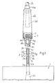
- the surgical drainage system includes a synthetic plastics bag 1 connected to a drainage line or hose 2a, 2b incorporating a coupling or connector assembly comprising a male or plug part 3 and a female or socket part 4.
- the plug and socket parts are formed, for example moulded, from suitable resilient, self- supporting, synthetic plastics material or materials.
- the plug part 3 includes a tubular, cylindrical body 3a, one end of which is secured at 2e, for example by welding or gluing, within an end of the section 2a of the drainage hose directly connected to the bag 1.
- the outer or distal end of the plug body 3a is closed by a transverse end wall 3b and, adjacent the end wall, the cylindrical side wall of the plug body is perforated by circumferentially extending openings 3c.
- a valve element comprising a cylindrical sleeve 3d closely fits the outer cylindrical surface of the plug body.
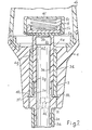
- the plug body is slidable axially within the sleeve 3d from a retracted or valve-closed position as shown in Figure 1, in which the outer or distal end of the sleeve is substantially flush with the planar outer surface of the transverse end wall 3b, and the sleeve overlies and seals off the openings 3c, to a valve-open position as shown in Figure 2, in which the distal end of the plug body 3a is advanced relative to the sleeve 3d to expose and open the openings 3c.
- the proximal end of the sleeve is provided with internal and external annular flanges 3e and 3f respectively.
- the internal flange 3e engages in a reduced diameter portion of the plug body, and is cooperable with stops formed by opposed shoulders 3g and 3h of the body to predetermine the range of sliding movement of the sleeve relative to the plug body.
- the shoulder 3h is formed at one end of an annular collar 3i integral with the plug body and formed with integral diametrically opposed pins 3k forming part of a bayonet-type locking arrangement.
- the sleeve 3d is initially assembled to the plug body 3a by pressing the flanged proximal end of the sleeve over the distal end of the plug body, and to simplify this operation, the internal flange 3e is formed with a tapered radially inner surface to provide a lead-in.
- the hose section 2a may terminate within the bag 1 in a non-return valve 2c (Fig. 2) which prevents liquid or gas within the bag from passing back up the hose.
- the socket part 4 is also tubular, and has a reduced diameter end portion 4a secured, for example by welding or gluing, to an end of the section 2b of drainage hose intended to be connected to a catheter or other drain.
- the end portion 4a communicates with one end of an enlarged diameter cylindrical transparent portion 4b defining a tubular chamber, the other end of the chamber communicating with a tubular socket body 4c internally dimensioned to slidably receive the plug part 3.
- the cylindrical portion 4b is sufficiently resilient or flexible to permit it to be compressed manually, and the hose section 2b terminates, within the chamber, in a non-return valve 2d which prevents liquid or gas, and any bacteria etc., within the chamber from passing back up the hose section.
- the non-return valve 2d (and the valve 2c) may be of the type which comprises a length of open-ended, flat or collapsed flexible tubing, formed, for example, from two elongate flat strips of plastics material welded together along their longer edges.
- the socket body 4c is provided, at its proximal end, with an internal annular flange 4d which serves as a stop for the sleeve 3d.
- the opening in the flange 4d is bounded by an annular ridge forming a seat 4e for a flap or disc valve element 5.
- the valve element 5 includes a circular, flat elastomeric sealing disc 5a bonded or otherwise secured to the flat end face of a closed-ended cylindrical support member 5b located within the cylindrical portion or chamber 4b.
- the disc valve element 5 is displaceable, and is biased by a coil spring 5c so as normally to urge the disc 5a towards the seat 4e to close, or tend to close, the opening in the flange 4d.
- the disc valve element 5 and bias spring 5c are located in a perforate housing 4f secured to the base of the cylindrical portion or chamber 4b, with the spring 5c maintained in compression between the disc valve element 5 and the underside of the top or end wall of the housing 4f.
- the inner diameter of the flange 4d i.e. the diameter of the opening in the flange, is approximately the same as the external diameter of the distal end region of the plug body 3a, so that the latter end region will be snugly slidably received by the flange when the plug and socket parts are connected together as shown in Figure 2.
- the cylindrical passage within the socket body 4c is provided with a reduced diameter region 4g adjacent the flange 4d, which is slightly smaller in diameter than the distal end of the sleeve 3d. Between the region 4 and an annular recess 4h, the internal diameter of the socket body 4c approximates or is slightly greater than the diameter of the sleeve 3d but less than the diameter of the external flange 3f.
- the distal region of the passage in the socket body 4c for example the region between the recess 4h and the open end of the body, may be internally stepped or tapered to provide an increased-diameter lead-in portion to facilitate insertion of the sleeve 3d. This distal region is also formed with a pair of slots 4i, forming part of the bayonet-type locking arrangement, and cooperable with the pins 3k.
- the connector assembly operates as follows:-
- the frictional cooperation between the plug body 3a and sleeve 3d is preferably initially greater than that between the sleeve 3d and internal surface of the socket body 4c. Therefore, the plug body and sleeve travel together, i.e. in their valve-closed position ( Figure 1), until the external flange 3f engages the distal end of the socket body 4c. Further insertion of the plug part then causes the plug body to advance relative to the sleeve until the proximal end of the sleeve engages the shoulder 3h.
- the sleeve 3d sealingly cooperates with the plug body 3a and socket body 4c, the distal end of the sleeve engages the flange 4d and sealingly cooperates with the reduced diameter region 4g, and the plug body is snugly received in the opening in the flange 4d, leakage between the plug and socket parts is prevented.
- the sleeve does not slide back on the plug body when, during insertion, the flange 3f engages the socket body, it will do so when its distal end encounters the region 4g. In any event, the sleeve will be positively driven fully home against the flange 4d, and the flange 3f will be snapped into the recess 4h, by engagement of the sleeve with the shoulder 3h.
- the flexible cylindrical socket portion 4b may be compressed, closing the non-return valve 2d, to pump or force the liquid through the openings and clear the blockage.
- the valve 2d isolates the patient from contaminants and pressure buildups downstream of the valve, and the valve 2c likewise prevents any contaminants, liquid, and pressure buildups in the bag from being transmitted to the connector assembly.
- the plug body 3a is firstly retracted relative to the socket body 4c and sleeve 3d until the upper surface of its transverse end wall 3b is flush with the upper edge of the valve seat 4e, so that the elastomeric disc 5a of the disc valve element 5 will seat and seal on the valve seat 4e without any significant voids, and therefore without any significant amounts of liquid being trapped, between the planar opposed surfaces of the disc 5a and distal end of the plug body.
- the non-return valve 2b may, prior to assembly, be secured to a short length of pipe or hose, the latter being secured within the end portion 4a of the socket part.
- the valve 2b may be positively centrally located within the cylindrical portion or chamber 4b to ensure that the valve does not contact the cylindrical wall of the chamber which may otherwise cause the valve to malfunction, for example, remain partially open, even when the pressure in the chamber exceeds the pressure in the hose section 2b.
- the socket body 4c may include a pair of concentric walls between which the lower end of the cylindrical portion 4b is mechanically located, and bonded or otherwise anchored in place.
- the cylindrical portion 4b may also be thickened adjacent its lower end to overlie the outer of the pair of concentric walls.
- the inner concentric wall may be provided by a flange on a separate re-entrant component, bonded into the socket body 4c, which also forms the housing 4f.
- the drainage hose for surgical drains from polythene since the hose will then be relatively flexible and soft, and therefore more comfortable to the patient.
- the bag of polythene in order to enable the hose and bag to be readily bonded together.
- disposal of. the polythene bags gives rise to problems since polythene, when incinerated, gives off corrosive or toxic by-products.
- the hose section 2b constitutes the major proportion of the overall length of the drainage hose and can be formed from polythene, whereas the relatively short hose section 2a, and therefore the bag 1, can be formed from polyvinyl chloride.
- Polyvinyl chloride can not only be disposed of by incineration without the production of toxic or corrosive by-products, but it is also a relatively cheap material to employ, and its use enables the hose section and bag assembly to be manufactured at a much higher rate.
- the connector assembly is relatively simple and fool-proof to manipulate, and is relatively simple and inexpensive to manufacture and assemble since it incorporates a minimum of individual components, all or the majority of which may be readily formed, for example moulded, from synthetic plastics material. It is economically viable for the connector assemblies to be treated as disposable items, avoiding the problems and expense of sterilization associated with re-use.
- the socket part and associated catheter may be retained connected to a patient, and used with a succession of plug parts and associated bags which are removed and disposed of when the bags are filled. When filled bags are unplugged, due to the effectively drip and void free valving arrangement, the risk of contamination being transmitted from or to the unplugged parts is effectively eliminated orsigni- ficantly reduced.
- the recess 4h in the socket body 4c could be replaced or supplemented by one or more ribs with which the sleeve flange 3f is releasably cooperable.
- Other means may be provided to ensure that, during and after removal of the plug part from the socket part, the sleeve is urged into, and/or indexed in, its closed position.
- the connector assembly is arranged with its plug part downstream of the socket part, the positions could be reversed.
- the disposition shown in the illustrated embodiment has the advantage that the valve element 5 is assisted in closing by the normal flow of liquid through the drainage system, and the element is conveniently disposed in the chamber in the enlarged diameter socket portion 4b.
- the valve element 5 could, furthermore, take a form other than that of a disc valve, for example it could comprise a flexible flap valve secured or hinged at one side to the flange 4d.
- connection and disconnection of the plug and socket parts is effected simply by a manual push or pull action respectively, accompanied by a twisting action to lock or unlock the bayonet-type locking arrangement
- the locking arrangement could be omitted, or could take the form of a snap-acting connection, screw thread-type connection, or other type of releasable lock.
- the shape, configurations and materials of the various components may be changed, and the connector assembly may be applied to liquid flow systems other than surgical drainage systems.
- plug and socket parts in the illustrated embodiment are permanently secured to the hose sections, they could alternatively be press-fitted or otherwise releasably attached to the hose sections or other fluid lines, etc.
- the plug and socket bodies could be formed, for example molded, integrally with the ends of their respective fluid lines, etc.
- the diameter of the disc valve element 5 may be reduced to a value approaching that of the valve seat 4e, and may be prevented from lateral displacement relative to the valve seat to positions in which it may not fully cover the valve seat by means of upright rib-like guides within the housing 4f or on the element 5b.
- the spring 5c, at its upper end, may be located laterally, for example located in a recess in the top of the housing 4f.
- the perforate housing 4fcould be replaced by a rib or equivalent mounted in the chamber in the socket part, with which the spring 5c, a sponge- like pad, or equivalent resilient element, cooperates.
- the housing or rib, and resilient element may be omitted, the disc or flap valve element relying on its own mass or resilience respectively, and/or the liquid pressure, to bias it to its closed position.
- the range of sliding movement of the sleeve may be determined by means other than the sleeve flange 3e which cooperates, alternatively, with the shoulders 3g and 3h.
- the shoulder 3h may be omitted, and instead, the flange 3e or equivalent may cooperate, with the distal end of the hose section 2a connected to the bag 1.
- the flange 4d may be omitted, and the sleeve may be permitted to project through the opening in the valve seat in the socket body 4c.
- the fully inserted position of the plug body will be determined by the bayonet-type locking arrangement or other stop means.
- the distal end of the plug body may have an annular shoulder of the same diameter as that of the seat opening and sleeve, against the underside of which the sleeve abuts in its valve-closed position.
- the transverse upper surfaces of the end wall 3b and the latter annular shoulder will be effectively flat and co-planar to ensure that, during unplugging, no voids are formed between the latter surfaces and the underside of the valve element as it closes on its seat, to avoid formation of drips.
- the drainage system may be employed with a hospitalised patient, although it could be used to advantage with a mobile patient as a urinary drain. In the latter case, since the likelihood of clots forming in the drained fluid is remote, it is not necessary to provide the pumping chamber 4b, and this may be omitted for reasons of space-and weight-saving, cost and convenience.
- the non-return valve 2d may be omitted, and the socket end portion 4a may be bonded directly to, or integrated with, the outer upper side wall of the socket body 4c.
- resilient cooperable snap-acting means may be provided to signify to a user when the plug and socket parts are fully engaged, and/or to index the sleeve in its valve-closed position during plugging or unplugging.
- the sleeve and/or plug body and/or socket body may be provided with annular ribs or other projections, and complementary cooperable grooves or depressions.
- the system for example the cylindrical socket portion 4b, may be provided with a vent or filter arrangement capable of venting gas (but not liquid) from the chamber in the event of a pressure build-up.
- a vent or filter arrangement may be incorporated in the hose section 2b or in the connection for connecting the hose section to the catheter.
- the vent arrangement may also include a portion penetrable by a syringe needle or luer to permit injection into or extraction from the arrangement.
- One or both of the non-return valves 2c, 2d may be omitted, or replaced by other types of valves.
Landscapes
- Health & Medical Sciences (AREA)
- Engineering & Computer Science (AREA)
- Heart & Thoracic Surgery (AREA)
- Public Health (AREA)
- Pulmonology (AREA)
- Anesthesiology (AREA)
- Biomedical Technology (AREA)
- Hematology (AREA)
- Life Sciences & Earth Sciences (AREA)
- Animal Behavior & Ethology (AREA)
- General Health & Medical Sciences (AREA)
- General Engineering & Computer Science (AREA)
- Veterinary Medicine (AREA)
- Mechanical Engineering (AREA)
- Quick-Acting Or Multi-Walled Pipe Joints (AREA)
- Infusion, Injection, And Reservoir Apparatuses (AREA)
- External Artificial Organs (AREA)
- Ultra Sonic Daignosis Equipment (AREA)
- Measuring Pulse, Heart Rate, Blood Pressure Or Blood Flow (AREA)
- Spectrometry And Color Measurement (AREA)
- Coupling Device And Connection With Printed Circuit (AREA)
- Paper (AREA)
- Connector Housings Or Holding Contact Members (AREA)
- Mechanical Operated Clutches (AREA)
- Materials For Medical Uses (AREA)
- Hydraulic Clutches, Magnetic Clutches, Fluid Clutches, And Fluid Joints (AREA)
Claims (10)
Priority Applications (1)
| Application Number | Priority Date | Filing Date | Title |
|---|---|---|---|
| AT82306262T ATE18720T1 (de) | 1981-11-25 | 1982-11-24 | Verbindung fuer fluessigkeitsleitungen. |
Applications Claiming Priority (2)
| Application Number | Priority Date | Filing Date | Title |
|---|---|---|---|
| GB8135609 | 1981-11-25 | ||
| GB8135609 | 1981-11-25 |
Publications (2)
| Publication Number | Publication Date |
|---|---|
| EP0080379A1 EP0080379A1 (de) | 1983-06-01 |
| EP0080379B1 true EP0080379B1 (de) | 1986-03-26 |
Family
ID=10526154
Family Applications (1)
| Application Number | Title | Priority Date | Filing Date |
|---|---|---|---|
| EP82306262A Expired EP0080379B1 (de) | 1981-11-25 | 1982-11-24 | Verbindung für Flüssigkeitsleitungen |
Country Status (12)
| Country | Link |
|---|---|
| EP (1) | EP0080379B1 (de) |
| JP (1) | JPS58109060A (de) |
| AT (1) | ATE18720T1 (de) |
| AU (1) | AU554339B2 (de) |
| CA (1) | CA1199354A (de) |
| DE (1) | DE3270165D1 (de) |
| DK (1) | DK159053C (de) |
| ES (1) | ES8400668A1 (de) |
| FI (1) | FI77775C (de) |
| NO (1) | NO152864C (de) |
| NZ (1) | NZ202591A (de) |
| ZA (1) | ZA828660B (de) |
Families Citing this family (11)
| Publication number | Priority date | Publication date | Assignee | Title |
|---|---|---|---|---|
| SE446656B (sv) * | 1985-01-08 | 1986-09-29 | Astra Meditec Ab | Ventilforsedd kopplingsanordning |
| DE3513205C1 (de) * | 1985-04-12 | 1987-01-15 | Fresenius Ag | Konnektor fuer die Peritonealdialyse |
| AT394656B (de) * | 1989-01-19 | 1992-05-25 | Dieringer Franz A | Kupplung fuer die verbindung von schlauchleitungen fuer medizinische zwecke |
| US5167238A (en) * | 1991-05-02 | 1992-12-01 | Cobe Laboratories, Inc. | Fluid sampling device |
| US5405333A (en) * | 1992-12-28 | 1995-04-11 | Richmond; Frank M. | Liquid medicament bag with needleless connector fitting using boat assembly |
| AU682670B2 (en) * | 1993-02-05 | 1997-10-16 | Becton Dickinson & Company | Syringe needle isolation device |
| JP2001170188A (ja) * | 1999-12-17 | 2001-06-26 | Terumo Corp | コネクタ |
| ES2245881B1 (es) * | 2004-06-09 | 2007-09-16 | Joan Conejero Sugrañes | Valvula para regular automaticamente el vaciado vesical en enfermos sondados. |
| CN102225223B (zh) * | 2011-06-08 | 2013-11-20 | 北京达必通科技开发有限公司 | 三环注射器 |
| CN110013575B (zh) * | 2019-05-21 | 2021-11-09 | 宋媛媛 | 一种手术室护理辅助装置 |
| CN113577404B (zh) * | 2021-07-27 | 2024-01-26 | 首都医科大学宣武医院 | 一种积液调控抽取装置 |
Citations (1)
| Publication number | Priority date | Publication date | Assignee | Title |
|---|---|---|---|---|
| CH337373A (de) * | 1955-12-28 | 1959-03-31 | Tetra Ag Fuer Hydraulische Bre | Kupplung für Schläuche oder Rohre |
Family Cites Families (7)
| Publication number | Priority date | Publication date | Assignee | Title |
|---|---|---|---|---|
| US3417750A (en) * | 1965-10-22 | 1968-12-24 | Bard Inc C R | Aspirating means and one-way valve |
| GB1192986A (en) * | 1967-08-31 | 1970-05-28 | Eschmann Bros & Walsh Ltd | Intravenous Valve Assembly |
| FR1585565A (de) * | 1968-10-08 | 1970-01-23 | ||
| US3642037A (en) * | 1969-12-04 | 1972-02-15 | Barr Stalfort Co | Liquid transfer system |
| US4143853A (en) * | 1977-07-14 | 1979-03-13 | Metatech Corporation | Valve for use with a catheter or the like |
| FI69351C (fi) * | 1979-01-22 | 1986-01-10 | Jan Axel Svensson | Slidventil- och kopplingsaggregat |
| DE3014527A1 (de) * | 1980-04-16 | 1981-10-22 | Tetra Werke Dr.Rer.Nat. Ulrich Baensch Gmbh, 4520 Melle | Steckverbindung fuer aquariendruckmittelleitungen |
-
1982
- 1982-10-25 AU AU90881/82A patent/AU554339B2/en not_active Ceased
- 1982-11-23 FI FI824026A patent/FI77775C/fi not_active IP Right Cessation
- 1982-11-24 EP EP82306262A patent/EP0080379B1/de not_active Expired
- 1982-11-24 NZ NZ202591A patent/NZ202591A/en unknown
- 1982-11-24 ES ES517639A patent/ES8400668A1/es not_active Expired
- 1982-11-24 ZA ZA828660A patent/ZA828660B/xx unknown
- 1982-11-24 NO NO823933A patent/NO152864C/no unknown
- 1982-11-24 DE DE8282306262T patent/DE3270165D1/de not_active Expired
- 1982-11-24 AT AT82306262T patent/ATE18720T1/de not_active IP Right Cessation
- 1982-11-24 CA CA000416298A patent/CA1199354A/en not_active Expired
- 1982-11-25 JP JP57208362A patent/JPS58109060A/ja active Pending
- 1982-11-25 DK DK524982A patent/DK159053C/da not_active IP Right Cessation
Patent Citations (1)
| Publication number | Priority date | Publication date | Assignee | Title |
|---|---|---|---|---|
| CH337373A (de) * | 1955-12-28 | 1959-03-31 | Tetra Ag Fuer Hydraulische Bre | Kupplung für Schläuche oder Rohre |
Also Published As
| Publication number | Publication date |
|---|---|
| DK159053B (da) | 1990-08-27 |
| CA1199354A (en) | 1986-01-14 |
| NO152864B (no) | 1985-08-26 |
| DE3270165D1 (en) | 1986-04-30 |
| FI77775C (fi) | 1989-05-10 |
| ATE18720T1 (de) | 1986-04-15 |
| AU554339B2 (en) | 1986-08-14 |
| AU9088182A (en) | 1983-06-02 |
| DK159053C (da) | 1991-01-28 |
| DK524982A (da) | 1983-05-26 |
| NZ202591A (en) | 1986-03-14 |
| FI77775B (fi) | 1989-01-31 |
| JPS58109060A (ja) | 1983-06-29 |
| ES517639A0 (es) | 1983-11-01 |
| FI824026L (fi) | 1983-05-26 |
| ZA828660B (en) | 1983-07-27 |
| NO823933L (no) | 1983-05-26 |
| NO152864C (no) | 1985-12-04 |
| EP0080379A1 (de) | 1983-06-01 |
| ES8400668A1 (es) | 1983-11-01 |
| FI824026A0 (fi) | 1982-11-23 |
Similar Documents
| Publication | Publication Date | Title |
|---|---|---|
| JP4738815B2 (ja) | バイアス式弁栓を備える自動封止雄ルーアーコネクタ | |
| EP0080379B1 (de) | Verbindung für Flüssigkeitsleitungen | |
| US4004590A (en) | Medical/surgical suction equipment | |
| EP0525080B1 (de) | Medizinische ventileinrichtung | |
| AU2002359895B2 (en) | Slit-type swabable valve | |
| US6572592B1 (en) | Medical valve and method of use | |
| JP3104905B2 (ja) | 医療用アクセス装置用バルブ付きアダプタ | |
| EP0175428B1 (de) | Tubuskupplung, insbesondere geeignet für mikrobentötende Bestrahlung | |
| US4681571A (en) | Suction canister with disposable liner and check valve | |
| EP0684050A2 (de) | Nadelfreier Zugang mit Abzweigventil | |
| US4431424A (en) | Arrangement in a sterilizing coupling | |
| EP0057177B1 (de) | Anordnung in einer sterilisierten kupplung | |
| AU2005205776B2 (en) | Medical valve | |
| HK1148966A (en) | Self-sealing male luer connector with biased valve plug | |
| HK1083717B (en) | Self-sealing male luer connector with biased valve plug |
Legal Events
| Date | Code | Title | Description |
|---|---|---|---|
| PUAI | Public reference made under article 153(3) epc to a published international application that has entered the european phase |
Free format text: ORIGINAL CODE: 0009012 |
|
| AK | Designated contracting states |
Designated state(s): AT BE CH DE FR GB IT LI NL SE |
|
| 17P | Request for examination filed |
Effective date: 19831112 |
|
| GRAA | (expected) grant |
Free format text: ORIGINAL CODE: 0009210 |
|
| AK | Designated contracting states |
Kind code of ref document: B1 Designated state(s): AT BE CH DE FR GB IT LI NL SE |
|
| REF | Corresponds to: |
Ref document number: 18720 Country of ref document: AT Date of ref document: 19860415 Kind code of ref document: T |
|
| ITF | It: translation for a ep patent filed | ||
| REF | Corresponds to: |
Ref document number: 3270165 Country of ref document: DE Date of ref document: 19860430 |
|
| ET | Fr: translation filed | ||
| PGFP | Annual fee paid to national office [announced via postgrant information from national office to epo] |
Ref country code: AT Payment date: 19861127 Year of fee payment: 5 |
|
| PLBE | No opposition filed within time limit |
Free format text: ORIGINAL CODE: 0009261 |
|
| STAA | Information on the status of an ep patent application or granted ep patent |
Free format text: STATUS: NO OPPOSITION FILED WITHIN TIME LIMIT |
|
| 26N | No opposition filed | ||
| PGFP | Annual fee paid to national office [announced via postgrant information from national office to epo] |
Ref country code: BE Payment date: 19890110 Year of fee payment: 7 |
|
| PG25 | Lapsed in a contracting state [announced via postgrant information from national office to epo] |
Ref country code: AT Effective date: 19891124 |
|
| PG25 | Lapsed in a contracting state [announced via postgrant information from national office to epo] |
Ref country code: LI Effective date: 19891130 Ref country code: CH Effective date: 19891130 Ref country code: BE Effective date: 19891130 |
|
| BERE | Be: lapsed |
Owner name: SCANDINAVIAN MEDICAL SUPPLY LTD Effective date: 19891130 |
|
| REG | Reference to a national code |
Ref country code: CH Ref legal event code: PL Ref country code: CH Ref legal event code: AUV Free format text: LE BREVET CI-DESSUS EST TOMBE EN DECHEANCE FAUTE DE PAIEMENT, DE LA 8E ANNUITE. |
|
| ITTA | It: last paid annual fee | ||
| PGFP | Annual fee paid to national office [announced via postgrant information from national office to epo] |
Ref country code: SE Payment date: 19921127 Year of fee payment: 11 Ref country code: FR Payment date: 19921127 Year of fee payment: 11 |
|
| PGFP | Annual fee paid to national office [announced via postgrant information from national office to epo] |
Ref country code: NL Payment date: 19921130 Year of fee payment: 11 |
|
| PG25 | Lapsed in a contracting state [announced via postgrant information from national office to epo] |
Ref country code: SE Effective date: 19931125 |
|
| PGFP | Annual fee paid to national office [announced via postgrant information from national office to epo] |
Ref country code: GB Payment date: 19940513 Year of fee payment: 12 |
|
| PGFP | Annual fee paid to national office [announced via postgrant information from national office to epo] |
Ref country code: DE Payment date: 19940520 Year of fee payment: 12 |
|
| PG25 | Lapsed in a contracting state [announced via postgrant information from national office to epo] |
Ref country code: NL Effective date: 19940601 |
|
| NLV4 | Nl: lapsed or anulled due to non-payment of the annual fee | ||
| PG25 | Lapsed in a contracting state [announced via postgrant information from national office to epo] |
Ref country code: FR Effective date: 19940729 |
|
| REG | Reference to a national code |
Ref country code: FR Ref legal event code: ST |
|
| PG25 | Lapsed in a contracting state [announced via postgrant information from national office to epo] |
Ref country code: GB Effective date: 19941124 |
|
| EUG | Se: european patent has lapsed |
Ref document number: 82306262.5 Effective date: 19940610 |
|
| GBPC | Gb: european patent ceased through non-payment of renewal fee |
Effective date: 19941124 |
|
| PG25 | Lapsed in a contracting state [announced via postgrant information from national office to epo] |
Ref country code: DE Effective date: 19950801 |