EP0080527A1 - Vorrichtung zum Schieben der Hülse eines Muffenventiles - Google Patents
Vorrichtung zum Schieben der Hülse eines Muffenventiles Download PDFInfo
- Publication number
- EP0080527A1 EP0080527A1 EP81110011A EP81110011A EP0080527A1 EP 0080527 A1 EP0080527 A1 EP 0080527A1 EP 81110011 A EP81110011 A EP 81110011A EP 81110011 A EP81110011 A EP 81110011A EP 0080527 A1 EP0080527 A1 EP 0080527A1
- Authority
- EP
- European Patent Office
- Prior art keywords
- sleeve
- port
- fluid
- port collar
- assembly
- Prior art date
- Legal status (The legal status is an assumption and is not a legal conclusion. Google has not performed a legal analysis and makes no representation as to the accuracy of the status listed.)
- Granted
Links
- 239000012530 fluid Substances 0.000 claims abstract description 73
- 238000012856 packing Methods 0.000 claims description 21
- 241001331845 Equus asinus x caballus Species 0.000 claims description 14
- 210000002445 nipple Anatomy 0.000 claims description 12
- 230000008878 coupling Effects 0.000 claims description 7
- 238000010168 coupling process Methods 0.000 claims description 7
- 238000005859 coupling reaction Methods 0.000 claims description 7
- 238000004891 communication Methods 0.000 claims description 4
- 238000000034 method Methods 0.000 claims description 3
- 230000000903 blocking effect Effects 0.000 claims 1
- 239000004568 cement Substances 0.000 description 4
- 230000002706 hydrostatic effect Effects 0.000 description 3
- 230000007257 malfunction Effects 0.000 description 2
- 238000010008 shearing Methods 0.000 description 1
- 239000002002 slurry Substances 0.000 description 1
Images

Classifications
-
- E—FIXED CONSTRUCTIONS
- E21—EARTH OR ROCK DRILLING; MINING
- E21B—EARTH OR ROCK DRILLING; OBTAINING OIL, GAS, WATER, SOLUBLE OR MELTABLE MATERIALS OR A SLURRY OF MINERALS FROM WELLS
- E21B34/00—Valve arrangements for boreholes or wells
- E21B34/06—Valve arrangements for boreholes or wells in wells
- E21B34/14—Valve arrangements for boreholes or wells in wells operated by movement of tools, e.g. sleeve valves operated by pistons or wire line tools
-
- E—FIXED CONSTRUCTIONS
- E21—EARTH OR ROCK DRILLING; MINING
- E21B—EARTH OR ROCK DRILLING; OBTAINING OIL, GAS, WATER, SOLUBLE OR MELTABLE MATERIALS OR A SLURRY OF MINERALS FROM WELLS
- E21B23/00—Apparatus for displacing, setting, locking, releasing or removing tools, packers or the like in boreholes or wells
- E21B23/04—Apparatus for displacing, setting, locking, releasing or removing tools, packers or the like in boreholes or wells operated by fluid means, e.g. actuated by explosion
- E21B23/0418—Apparatus for displacing, setting, locking, releasing or removing tools, packers or the like in boreholes or wells operated by fluid means, e.g. actuated by explosion specially adapted for locking the tools in landing nipples or recesses
-
- E—FIXED CONSTRUCTIONS
- E21—EARTH OR ROCK DRILLING; MINING
- E21B—EARTH OR ROCK DRILLING; OBTAINING OIL, GAS, WATER, SOLUBLE OR MELTABLE MATERIALS OR A SLURRY OF MINERALS FROM WELLS
- E21B23/00—Apparatus for displacing, setting, locking, releasing or removing tools, packers or the like in boreholes or wells
- E21B23/04—Apparatus for displacing, setting, locking, releasing or removing tools, packers or the like in boreholes or wells operated by fluid means, e.g. actuated by explosion
- E21B23/0422—Apparatus for displacing, setting, locking, releasing or removing tools, packers or the like in boreholes or wells operated by fluid means, e.g. actuated by explosion characterised by radial pistons
-
- E—FIXED CONSTRUCTIONS
- E21—EARTH OR ROCK DRILLING; MINING
- E21B—EARTH OR ROCK DRILLING; OBTAINING OIL, GAS, WATER, SOLUBLE OR MELTABLE MATERIALS OR A SLURRY OF MINERALS FROM WELLS
- E21B33/00—Sealing or packing boreholes or wells
- E21B33/10—Sealing or packing boreholes or wells in the borehole
- E21B33/13—Methods or devices for cementing, for plugging holes, crevices or the like
- E21B33/14—Methods or devices for cementing, for plugging holes, crevices or the like for cementing casings into boreholes
Definitions
- the invention relates to a tool for shifting a sleeve positioned slideably inside of a tubular member, such as a well casing.
- the tool is designed for shifting a slidable sleeve inside of a port collar, of the type used in well cementing operations.
- a well casing When boreholes are drilled to recover oil or gas, a well casing is lowered into the hole and cemented, usually at the lower end of the hole and frequently at other locations above the lower end.
- primary cementing When the lower end of the casing is cemented, usually referred to as primary cementing, a cement slurry is passed down through the casing and up into the annular space defined between the casing and the borehole. Cementing above the lower end of the borehole is usually done later than the primary cementing job, that is, during the productive life of the well. The later operations are sometimes referred to as secondary cementing, or stage cementing.
- a port collar can be generally described as a coupling between sections of well casing which has openings (ports) in the collar wall. Positioned inside the collar is a sliding sleeve, referred to as a port collar sleeve, which also has ports in the sleeve wall. Prior to cementing, the sleeve is in a position such that it closes off the collar ports. When it is desired to pump cement into the borehole annulus through the openings in the port collar, a shifting tool is used to slide the sleeve to a position in which the sleeve ports and collar ports are in direct alignment.
- the shifting tool of this invention overcomes the problems mentioned above, by providing an engaging mechanism which operates by hydraulic fluid pressure, rather than by mechanical linkage.
- the tool described herein is also simpler to operate than the prior tools because of fewer moving parts.
- this tool can pass through any number of port collars in a given drill string. This feature enables the tool to engage and shift each port collar sleeve an indefinite number of times in a given operation.
- the tool of this invention is useful for shifting a sleeve positioned slideably inside a tubular section, such as a well casing.
- the present tool is designed for shifting a port collar sleeve to open and close the ports in the collar.
- the port collar is coupled between sections of a well casing and it has fluid outlet ports therein.
- the port collar sleeve, which is slideable inside the collar also has fluid outlet ports therein.
- This device includes a shifting tool assembly which, in an operating position, sets or locks inside of the port collar sleeve.
- the shifting tool assembly is made up of a housing member and a piston assembly. Inside the housing member is a lengthwise bore, which is intersected by a transverse bore. The bottom end of a tubing string, which is positioned in the well casing is connected to the housing member and in fluid communication with the lengthwise bore. At the top end, the tubing string is connected to a source of an operating fluid.
- the piston assembly is made up of at least one piston section which is slideable along the transverse bore of the housing member.
- Each piston section includes an inner piston section and an outer piston section.
- the inner piston section has an operating face
- the outer piston section has a seating face.
- the shifting tool also includes a hollow mandrel, a packing sleeve assembly, and a check valve assembly.
- the mandrel is connected to the housing member in fluid communication with the lengthwise bore in the housing member. Fluid outlet ports are provided in the mandrel.
- the packing sleeve assembly is positioned on the outside of the mandrel such that it normally covers the fluid outlet ports in the mandrel. In another position, the packing sleeve remains in place in the well casing and the mandrel slides upwardly through the sleeve to uncover the fluid outlet ports.
- the check valve assembly is positioned within the mandrel. This valve has a closed position in which fluid is blocked from flowing through the mandrel. In addition, the check valve has an open position in which fluid can flow through the mandrel.
- the present invention resides in a well tool for shifting a port collar sleeve, the sleeve being slideably positioned inside a port collar, and the sleeve having a groove defined on the inside wall surface thereof, the tool comprising:
- the invention also resides in a method for shifting a port collar sleeve on a well tool comprising the steps of:
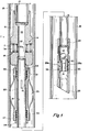
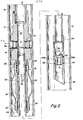
- the shifting tool assembly of this invention is designated generally by the letter T.
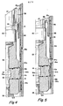
- the basic tool consists of a housing member 10 and a piston assembly, which includes an outer piston section 11 and an inner piston section 12. Inside the housing member 10 is a lengthwise bore 13, which is intersected by a tranverse bore 14. The piston assembly is positioned to slide laterally within the bore 14.
- the bore 14 is indicated generally in FIGURES 1, 2 and 3, but it is best shown in the detail views of FIGURES 4 and 5.
- the tool T is lowered into a well casing 15.
- Sections of the well casing 15 can be coupled together by one or more port collars 16.
- the port collar 16 is shown only in the detail views of FIGURES 4 and 5.
- the top end of the housing member 10 is coupled to the bottom end of a tubing string 17, such that the tubing string communicates with the bore 13 in the housing member.
- the other end of the tubing string is connected to a source of an operating fluid.
- the fluid source is not illustrated herein.
- a hollow mandrel 18 is coupled to the bottom end of the bore 13 in housing member 10. Near the top end of mandrel 18 are several fluid outlet ports 19.
- a packing sleeve assembly is positioned to slide up and down on the outside of mandrel 18 below the shifting tool assembly.
- a packing sleeve 20 defines the main part of this assembly.
- An upper packing element 21 is sandwiched between the sleeve 20 and mandrel 18, to seal the upper end of the sleeve.
- the sleeve 20 is sealed by a lower packing element 22.
- Packing element 21 is held in place by a retainer ring 23.
- a similar retainer ring 24 holds the packing element 22 in place.
- the packing sleeve also includes several drag springs, which are indicated by numeral 25. Each drag spring is fastened to the top end of the packing sleeve 20 by a retainer ring 26. At the bottom of the sleeve a second retainer ring 27 clamps the springs to the sleeve.
- a mule shoe 28 is fastened to the bottom end of the mandrel 18 by a coupling 29.
- a check valve assembly is positioned inside of the mule shoe.
- the check valve is made up of a nipple section 30, which has a lengthwise bore 31 therein, and a ball 32.
- a set of shear screws 33 holds the nipple section 30 in place inside the mule shoe 28.
- the nipple section 30 In its normal position inside the mule shoe 28, as illustrated in the drawing, the nipple section 30 seals off the fluid outlet ports 28a in the mule shoe.
- a port collar sleeve 34 is positioned inside the port collar 16.
- the port collar includes several fluid outlet ports 16a, and similar fluid outlet ports 34a are defined in the wall of sleeve 34.
- Numeral 35 refers to alternating fingers and slots, which are machined into the top end of sleeve 34.
- the fingers and slots 35 on sleeve 34 are adapted to mesh with a corresponding set of alternating fingers and slots 36, which are machined into the bottom end of a coupling 15a.
- the coupling 15a actually connects the port collar 16, at its top end, to a section of the well casing 15.
- the upwardly-directed fingers and slots 35 mesh with the downwardly-directed fingers and slots 36 only when the port. collar sleeve 34 is shifted upwardly.
- the invention can be illustrated by describing the use of the present shifting tool in a typical well cementing operation.
- the shifting tool Prior to injecting cement into the well casing 15, the shifting tool is run into the casing 15 on the end of the tubing string 17, until it reaches a point just above the port collar 16.
- the ball 32 is unseated from the bore 31 in nipple section 30.
- the ball is unseated by the pressure of that part of the fluid which passes upwardly through the mule shoe 18 and into the mandrel 18, the housing member 10, and the tubing string 17.
- the rest of the fluid in the well casing will remain on the outside of the shifting tool, that is, between the shifting tool and the casing, during the run-in step.
- the piston assembly is held in the retracted position by the hydrostatic pressure of that part of the fluid which remains on the outside of the tool.
- the surface area of the seating face lla of outer piston section 11 is greater than the surface area of the operating face 12a of inner piston section 12.
- the fluid pressure which bears against the seating face lla of outer piston section 11, during the running-in step is greater than the fluid pressure which bears against the operating face 12a of inner piston section 12.
- a set of collet fingers 34c which are mounted on sleeve 34, latch into a recess 16b on the port collar 16.
- the purpose of these collet fingers is to provide an additional means for properly locating the sleeve 34 relative to the port collar 16.
- the next step is to disengage the shifting tool from sleeve 34. This is done by releasing pressure on the fluid in the tubing string, so that the piston assembly will retract.
- the tubing string 17 is pulled upwardly to remove the shifting tool from the well casing. Cement can then be pumped down the casing 15 and into the borehole annulus (not shown) through the aligned open ports 34a and 16a in the sleeve and collar assembly.
- the pressure build-up in the string can be prevented by another means. For example, if such a malfunction takes place, sufficient pressure is applied to the fluid in the tubing string to shear the screws 33 which secure the nipple section 30 to the mule shoe 28. Shearing the screws 33 allows the nipple section 30 and ball 32 to slide down past the outlet ports 28a in the mule shoe. The fluid in the tubing string can then circulate into the casing through the open ports 28a in the mule shoe.
- the next step is to close the outlet ports in the port collar 16. This is done by running the shifting tool back into the well casing 15 to re-engage the port collar sleeve 34 in the same manner as described earlier. Once the piston assembly re-engages port collar sleeve 34, and is locked into place, enough weight is set on the tubing string 17 to move the sleeve back down to its original position (the position shown in FIGURE 4), so that the sleeve again closes off the ports in collar 16.
Landscapes
- Life Sciences & Earth Sciences (AREA)
- Engineering & Computer Science (AREA)
- Geology (AREA)
- Mining & Mineral Resources (AREA)
- Physics & Mathematics (AREA)
- Environmental & Geological Engineering (AREA)
- Fluid Mechanics (AREA)
- General Life Sciences & Earth Sciences (AREA)
- Geochemistry & Mineralogy (AREA)
- Earth Drilling (AREA)
Priority Applications (2)
| Application Number | Priority Date | Filing Date | Title |
|---|---|---|---|
| EP81110011A EP0080527B1 (de) | 1981-11-30 | 1981-11-30 | Vorrichtung zum Schieben der Hülse eines Muffenventiles |
| OA57561A OA06964A (fr) | 1981-11-30 | 1981-12-08 | Dispositif et procédé pour déplacer un manchon de bague perforée à l'intérieur d'un élément tubulaire, tel que le tubage d'un puits. |
Applications Claiming Priority (1)
| Application Number | Priority Date | Filing Date | Title |
|---|---|---|---|
| EP81110011A EP0080527B1 (de) | 1981-11-30 | 1981-11-30 | Vorrichtung zum Schieben der Hülse eines Muffenventiles |
Publications (2)
| Publication Number | Publication Date |
|---|---|
| EP0080527A1 true EP0080527A1 (de) | 1983-06-08 |
| EP0080527B1 EP0080527B1 (de) | 1985-08-28 |
Family
ID=8188045
Family Applications (1)
| Application Number | Title | Priority Date | Filing Date |
|---|---|---|---|
| EP81110011A Expired EP0080527B1 (de) | 1981-11-30 | 1981-11-30 | Vorrichtung zum Schieben der Hülse eines Muffenventiles |
Country Status (2)
| Country | Link |
|---|---|
| EP (1) | EP0080527B1 (de) |
| OA (1) | OA06964A (de) |
Cited By (3)
| Publication number | Priority date | Publication date | Assignee | Title |
|---|---|---|---|---|
| EP0224942A1 (de) * | 1985-10-04 | 1987-06-10 | Compagnie Des Services Dowell Schlumberger | Gerät zur abschnittweisen Zementation |
| EP1915507A4 (de) * | 2005-08-18 | 2013-04-24 | Peak Well Solutions As | Vorrichtung zum leiten von zementiervorgängen und zustromregelung |
| WO2020181359A1 (en) | 2019-03-13 | 2020-09-17 | Ncs Multistage Inc. | Bottomhole assembly |
Citations (8)
| Publication number | Priority date | Publication date | Assignee | Title |
|---|---|---|---|---|
| DE126731C (de) * | ||||
| US2549198A (en) * | 1945-10-13 | 1951-04-17 | Landes H Hayward | Well cementing apparatus |
| US2598396A (en) * | 1947-02-24 | 1952-05-27 | Baker Oil Tools Inc | Apparatus for cementing well casings |
| US2667926A (en) * | 1948-08-12 | 1954-02-02 | Thomas E Alexander | Apparatus for cementing wells |
| US2901044A (en) * | 1955-07-07 | 1959-08-25 | Edward W Arnold | Pulling tool |
| US2973038A (en) * | 1956-11-19 | 1961-02-28 | Bowen Itco Inc | Hydraulic pulling tool |
| US3768562A (en) * | 1972-05-25 | 1973-10-30 | Halliburton Co | Full opening multiple stage cementing tool and methods of use |
| US3865188A (en) * | 1974-02-27 | 1975-02-11 | Gearhart Owen Industries | Method and apparatus for selectively isolating a zone of subterranean formation adjacent a well |
-
1981
- 1981-11-30 EP EP81110011A patent/EP0080527B1/de not_active Expired
- 1981-12-08 OA OA57561A patent/OA06964A/xx unknown
Patent Citations (8)
| Publication number | Priority date | Publication date | Assignee | Title |
|---|---|---|---|---|
| DE126731C (de) * | ||||
| US2549198A (en) * | 1945-10-13 | 1951-04-17 | Landes H Hayward | Well cementing apparatus |
| US2598396A (en) * | 1947-02-24 | 1952-05-27 | Baker Oil Tools Inc | Apparatus for cementing well casings |
| US2667926A (en) * | 1948-08-12 | 1954-02-02 | Thomas E Alexander | Apparatus for cementing wells |
| US2901044A (en) * | 1955-07-07 | 1959-08-25 | Edward W Arnold | Pulling tool |
| US2973038A (en) * | 1956-11-19 | 1961-02-28 | Bowen Itco Inc | Hydraulic pulling tool |
| US3768562A (en) * | 1972-05-25 | 1973-10-30 | Halliburton Co | Full opening multiple stage cementing tool and methods of use |
| US3865188A (en) * | 1974-02-27 | 1975-02-11 | Gearhart Owen Industries | Method and apparatus for selectively isolating a zone of subterranean formation adjacent a well |
Cited By (4)
| Publication number | Priority date | Publication date | Assignee | Title |
|---|---|---|---|---|
| EP0224942A1 (de) * | 1985-10-04 | 1987-06-10 | Compagnie Des Services Dowell Schlumberger | Gerät zur abschnittweisen Zementation |
| EP1915507A4 (de) * | 2005-08-18 | 2013-04-24 | Peak Well Solutions As | Vorrichtung zum leiten von zementiervorgängen und zustromregelung |
| WO2020181359A1 (en) | 2019-03-13 | 2020-09-17 | Ncs Multistage Inc. | Bottomhole assembly |
| EP3938616A4 (de) * | 2019-03-13 | 2023-03-22 | NCS Multistage Inc. | Bohrlochsohlenvorrichtung |
Also Published As
| Publication number | Publication date |
|---|---|
| EP0080527B1 (de) | 1985-08-28 |
| OA06964A (fr) | 1983-07-31 |
Similar Documents
| Publication | Publication Date | Title |
|---|---|---|
| US4312406A (en) | Device and method for shifting a port collar sleeve | |
| US5048611A (en) | Pressure operated circulation valve | |
| EP0192399B1 (de) | Vorrichtung zur Behandlung von Bohrlöchern | |
| US7066264B2 (en) | Method and apparatus for treating a subterranean formation | |
| US5921318A (en) | Method and apparatus for treating multiple production zones | |
| US6216785B1 (en) | System for installation of well stimulating apparatus downhole utilizing a service tool string | |
| US6142226A (en) | Hydraulic setting tool | |
| US6343658B2 (en) | Underbalanced well completion | |
| US4606408A (en) | Method and apparatus for gravel-packing a well | |
| US6152232A (en) | Underbalanced well completion | |
| EP0728914B1 (de) | Bohrloch-Zementierungswerkzeug | |
| CA2445870C (en) | Automatic tubing filler | |
| EP0192398A2 (de) | Vorrichtung zum Einsetzen von Linern in Bohrlöchern | |
| US20020070023A1 (en) | Multi-zone completion strings and methods for multi-zone completions | |
| US6182766B1 (en) | Drill string diverter apparatus and method | |
| NO342477B1 (no) | Utreverserende ventil for brønnbehandlingsprosedyrer | |
| US6082459A (en) | Drill string diverter apparatus and method | |
| GB2310678A (en) | A packer for a wellbore | |
| US4804044A (en) | Perforating gun firing tool and method of operation | |
| EP0589686B1 (de) | Durch Differenzdruck betätigtes Ventil im Bohrloch | |
| US5253712A (en) | Rotationally operated back pressure valve | |
| US20030221839A1 (en) | Double-pin radial flow valve | |
| WO1988001678A1 (en) | Method and apparatus for multi-stage cementing of a well casing | |
| EP0080527B1 (de) | Vorrichtung zum Schieben der Hülse eines Muffenventiles | |
| CA1163554A (en) | Device and method for shifting a port collar sleeve |
Legal Events
| Date | Code | Title | Description |
|---|---|---|---|
| PUAI | Public reference made under article 153(3) epc to a published international application that has entered the european phase |
Free format text: ORIGINAL CODE: 0009012 |
|
| AK | Designated contracting states |
Designated state(s): FR GB IT NL |
|
| 17P | Request for examination filed |
Effective date: 19830718 |
|
| ITF | It: translation for a ep patent filed | ||
| GRAA | (expected) grant |
Free format text: ORIGINAL CODE: 0009210 |
|
| AK | Designated contracting states |
Designated state(s): FR GB IT NL |
|
| ET | Fr: translation filed | ||
| PLBE | No opposition filed within time limit |
Free format text: ORIGINAL CODE: 0009261 |
|
| STAA | Information on the status of an ep patent application or granted ep patent |
Free format text: STATUS: NO OPPOSITION FILED WITHIN TIME LIMIT |
|
| 26N | No opposition filed | ||
| PGFP | Annual fee paid to national office [announced via postgrant information from national office to epo] |
Ref country code: NL Payment date: 19871130 Year of fee payment: 7 |
|
| PG25 | Lapsed in a contracting state [announced via postgrant information from national office to epo] |
Ref country code: GB Effective date: 19881130 |
|
| PG25 | Lapsed in a contracting state [announced via postgrant information from national office to epo] |
Ref country code: NL Effective date: 19890601 |
|
| NLV4 | Nl: lapsed or anulled due to non-payment of the annual fee | ||
| GBPC | Gb: european patent ceased through non-payment of renewal fee | ||
| PG25 | Lapsed in a contracting state [announced via postgrant information from national office to epo] |
Ref country code: FR Free format text: LAPSE BECAUSE OF NON-PAYMENT OF DUE FEES Effective date: 19890731 |
|
| REG | Reference to a national code |
Ref country code: FR Ref legal event code: ST |