EP0080618A2 - Elektrostatische Koalesziereinrichtung - Google Patents
Elektrostatische Koalesziereinrichtung Download PDFInfo
- Publication number
- EP0080618A2 EP0080618A2 EP82110339A EP82110339A EP0080618A2 EP 0080618 A2 EP0080618 A2 EP 0080618A2 EP 82110339 A EP82110339 A EP 82110339A EP 82110339 A EP82110339 A EP 82110339A EP 0080618 A2 EP0080618 A2 EP 0080618A2
- Authority
- EP
- European Patent Office
- Prior art keywords
- electrodes
- voltage
- pair
- mixture
- rectifier
- Prior art date
- Legal status (The legal status is an assumption and is not a legal conclusion. Google has not performed a legal analysis and makes no representation as to the accuracy of the status listed.)
- Withdrawn
Links
Images

Classifications
-
- B—PERFORMING OPERATIONS; TRANSPORTING
- B01—PHYSICAL OR CHEMICAL PROCESSES OR APPARATUS IN GENERAL
- B01D—SEPARATION
- B01D17/00—Separation of liquids, not provided for elsewhere, e.g. by thermal diffusion
- B01D17/06—Separation of liquids from each other by electricity
Definitions
- the present invention relates to the simultaneous generation of a DC electrostatic field and an AC type of electrostatic field through which a two-phase mixture of immiscible polar and non-polar liquids is sequentially passed and the dispersed droplets of polar liquid are coalesced into sizes large enough for their effective gravitation from the mixture. More particularly, the invention relates to providing a circuit for electrodes which are energized to generate a DC electrostatic field and an AC type of electrostatic field, which circuits are controlled by rectifiers to limit the DC potential between the electrodes as the dielectric strength of the liquids between the electrodes decreases.
- a mixture-of oil and water represents the medium passed sequentially through the DC and AC type of electrostatic fields generated by the electrodes.
- the mixture may be more generally defined as that of a polar liquid finely dispersed and in an immiscible non-polar liquid.
- the disclosure can refer to either a two-phase mixture of immiscible polar and non-polar liquids, or a mixtt:re of oil and water.
- U. S. patent 4,049,535 discloses one arrangement to maintain the DC field while the load impedance of the emulsion is low.
- the addition of the full-wave rectifier, utilizing a grounded center-tap transformer eliminates the AC field.
- the opposing voltages generated cancel each other, resulting in zero voltage between the combined electrodes and ground.
- This arrangement destroys the valuable AC field required in the sequential application of the two electrostatic fields.
- a circuit arrangement is needed which will sustain a DC field of significant strength without significantly reducing the strength of the AC field.
- the present invention contemplates connecting at least one rectifier in the dual polarity circuit to maintain a predetermined minimum DC voltage between energized electrodes when the impedance of the medium between the electrodes decreases while also maintaining an AC field between the electrodes and the ground reference. This arrangement will also allow the reestablishment of normal DC operating potentials when the impedance of the medium between the electrodes increases to its original value.
- the disclosure carefully characterizes the medium in which electrostatic fields are sustained between charged electrodes.
- the broadest description refers to a mixture of two liquids which are immiscible relative to each other, one liquid being more polar than the other.
- the mixture is referred to as an emulsion.
- an emulsion of oil and water is common. Oil and water fall into the category of two liquids which are immiscible relative to each other, the water being the more polar and dispersed in the form of droplets within the less polar oil.
- the rectifier has been a unit of electric circuits for many years. Recently, the term diode has been applied to devices which function as the rectifier functions. Further, it has become the practice to refer to a diode stack as the unit which is essentially a plurality of rectifiers in series. Those skilled in the art should not be confused between the terms rectifier, diode, and diode stacks, as they are all electrically equivalent and can be designated with a common symbol.
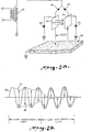
- a third electrode 3 is constructively formed as the upper surface of the body of relatively polar conductive liquid below the electrodes 1 and 2 which has been coalesced from the mixture.
- transformer 4 the arrangement of the electrodes 1, 2 and 3 are familiar from the disclosures of the incorporated patents.
- the AC form of electrostatic field generated between the lower ends of electrodes 1 and 2 and surface electrode 3 is a feature familiar from the incorporated disclosures.
- the DC electrostatic field is generated between electrodes 1 and 2.
- the liquid mixture flows sequentially through the AC type of field and the DC field so that the two electrostatic fields may effectively coalesce the droplets of polar liquid to a size which will enable them to gravitate into and join the lower body of liquid having surface 3.
- the electrodes 1 and 2 are connected in parallel to transformer 4, the separate connections containing oppositely poled rectifiers 5 and 6, as symbolized in Fig. la.
- the AC voltage applied from transformer 4 develops the two electrostatic fields with strengths depending upon the dielectric strength of the mixture.
- the problem met by this disclosure develops when this dielectric strength, and consequent impedance of the mixture, decreases to a value which yields the results charted in Fig. lb.
- Fig. Ib is, essentially, a chart of the voltage variations in the circuit of Fig. la.
- the AC voltage of the transformer 4 is represented by sinusoidal curve 10.
- the first two complete cycles shown of this applied voltage of curve 10 generate the voltage on electrode 1, as represented by curve 11.
- Curve 12 represents the voltage appearing on electrode 2.
- curves 11 and 12 represents the voltage between electrodes 1 and 2 with their DC electrostatic field generated between them.
- the vertical distance between curves 11 and 12, during the first two cycles of the applied voltage of curve 10 represent the value of this DC voltage when the dielectric strength of the liquid mixture between the electrodes is relatively high.
- first two cycles of the voltage curves in Fig. Ib may be described as normal operation.
- the curves have been extended to form the subsequent two cycles in illustration of the problem to be solved.
- the transition does not take place as abruptly as illustrated by the lack of transition between the first two cycles and the last two cycles.
- the common sense of one skilled in the art permits the juxtaposition of the two pairs of cycles to illustrate the problem solved by the invention.
- the last two cycles of the applied voltage of curve 10 are displayed with the extensions of curves 11 and 12 to demonstrate the decrease of the DC potential between electrodes 1 and 2.
- the voltage on the undriven electrode of 1 and 2 closely follows the voltage on the driven electrode.
- the DC voltage appearing between the two electrodes is represented by the small, vertical distance between the two electrode voltages. The result is that the DC electrostatic field deteriorates to such a low value that it becomes ineffective to coalesce the polar liquid dispersed in the non-polar liquid.
- the voltage of the positively charged electrode actually passes through zero voltage and is negatively charged for a portion of each applied voltage cycle.
- the voltage of the negatively charged electrode actually passes through zero voltage and is positively charged for a portion of each voltage cycle.
- This novel circuit insures that there will always be at least transformer voltage between the electrodes, within the power output limits of the transformer, during the period of low impedance between the electrodes.
- the circuit addition incorporated will not allow either electrodes 1 or 2 to reverse polarity.
- the voltage on the undriven electrode is clamped to zero, or ground potential, if the voltage attempts to reverse its polarity.
- Fig. 2a discloses a circuit generally similar to that of Fig. la. Electrodes 20 and 21 are spaced from each other in the stream of liquid mixture processed by the electrostatic fields between electrodes 20, 21 and surface electrode 22. Electrodes 20 and 21 are connected in parallel to transformer 23 through oppositely poled rectifiers 24 and 25..
- Fig. 2b is generally similar to Fig. lb in' that it is a chart of the voltage variations of the circuit of Fig. 2a as embodying the invention.
- the present invention embodies the concept of providing an electrical circuit with low impedance to ground when the voltages on electrodes 20 and 21 attempt to reverse their intended polarity.
- rectifier 26 is connected between electrode 20 and ground
- rectifier 27 is connected between electrode 21 and ground potential. Oriented as symbolized in Fig. 2a, these rectifiers function to limit the potential, relative to ground, of each non-driven electrode to zero as a potential of opposite polarity is applied to the driven electrode.
- the voltage chart of Fig. 2b shows the first two cycles of applied sinusoidal voltage represented as curve 30, while the electrode voltages are represented as curves 31 and 32.
- the first 2 cycles of applied voltage of curve 30 essentially duplicate the voltage patterns of the first two cycles of applied voltage in Fig. lb.
- the last two cycles of applied voltage of curve 30 illustrate the voltage limitation of electrodes 20 and 21, as charted by curves 31 and 32. Limited to zero, or ground, potential .when the dielectric strength between the electrodes is relatively low, the DC potential between the electrodes is represented by the vertical distance between curves 31 and 32. In comparison of this differential with that of the last two cycles of curves 11 and 12 of Fig. lb, there is demonstrated the effectiveness of the present invention to maintain the DC potential to a significant value during the periods when the mixture between the electrodes is of relatively low dielectric strength.
- the invention merely prevents the potential difference between electrodes 20 and 21 from collapsing to such a low value that their electrostatic field is ineffective in bringing about coalescence.
- the invention is embodied in the circuit provided by connecting rectifiers 26 and 27 between electrodes 20 and 21 and ground potential. Of course, these rectifiers are poled oppositely of each other and reverse biased when the associated electrode is driven to provide the required function to carry out the invention.
- Fig. 2a discloses the complete circuit, or electrical network, in which the .invention is embodied, and the voltage chart of Fig. 2b dramatically discloses the limitation imposed upon the electrode voltages to maintain the differential required.
Landscapes
- Physics & Mathematics (AREA)
- Thermal Sciences (AREA)
- Chemical & Material Sciences (AREA)
- Chemical Kinetics & Catalysis (AREA)
- Physical Or Chemical Processes And Apparatus (AREA)
- Production Of Liquid Hydrocarbon Mixture For Refining Petroleum (AREA)
- Electrostatic Separation (AREA)
- Rectifiers (AREA)
- Water Treatment By Electricity Or Magnetism (AREA)
Applications Claiming Priority (2)
| Application Number | Priority Date | Filing Date | Title |
|---|---|---|---|
| US06/325,799 US4417971A (en) | 1981-11-30 | 1981-11-30 | Circuit for maintaining the strength of an electrostatic field generated in a fluid mixture of varying dielectric strength |
| US325799 | 1989-03-20 |
Publications (2)
| Publication Number | Publication Date |
|---|---|
| EP0080618A2 true EP0080618A2 (de) | 1983-06-08 |
| EP0080618A3 EP0080618A3 (de) | 1983-12-14 |
Family
ID=23269500
Family Applications (1)
| Application Number | Title | Priority Date | Filing Date |
|---|---|---|---|
| EP82110339A Withdrawn EP0080618A3 (de) | 1981-11-30 | 1982-11-10 | Elektrostatische Koalesziereinrichtung |
Country Status (5)
| Country | Link |
|---|---|
| US (1) | US4417971A (de) |
| EP (1) | EP0080618A3 (de) |
| JP (1) | JPS58104647A (de) |
| KR (1) | KR840002249A (de) |
| CA (1) | CA1179973A (de) |
Cited By (2)
| Publication number | Priority date | Publication date | Assignee | Title |
|---|---|---|---|---|
| EP0468954A3 (en) * | 1990-07-27 | 1992-04-01 | Voest-Alpine Industrieanlagenbau Gesellschaft M.B.H. | Method for breaking emulsions |
| EP0645169A1 (de) * | 1993-09-23 | 1995-03-29 | Armand Ajdari | Verbesserung der Verfahren und Vorrichtungen zum Abtrennen von Teilchen in einem Fluidstrom |
Families Citing this family (9)
| Publication number | Priority date | Publication date | Assignee | Title |
|---|---|---|---|---|
| WO1996010618A1 (en) * | 1994-09-30 | 1996-04-11 | Sgi International | Electrodynamic-chemical processing for beneficiation of petroleum residue |
| US6673135B2 (en) * | 2002-02-08 | 2004-01-06 | National Tank Company | System and method of separating entrained immiscible liquid component of an inlet stream |
| US6860979B2 (en) * | 2002-08-07 | 2005-03-01 | National Tank Company | Dual frequency electrostatic coalescence |
| US7758738B2 (en) | 2002-08-07 | 2010-07-20 | National Tank Company | Separating multiple components of a stream |
| US7351320B2 (en) * | 2002-08-07 | 2008-04-01 | National Tank Company | Multiple frequency electrostatic coalescence |
| US8591714B2 (en) | 2007-04-17 | 2013-11-26 | National Tank Company | High velocity electrostatic coalescing oil/water separator |
| US9095790B2 (en) | 2012-06-08 | 2015-08-04 | Cameron International Corporation | High velocity electrostatic coalescing oil/water separator |
| US10392568B2 (en) * | 2013-11-26 | 2019-08-27 | Phillips 66 Company | Sequential mixing system for improved desalting |
| US11398781B2 (en) * | 2019-11-05 | 2022-07-26 | Cameron International Corporation | Power supply unit, system and method for coalescence of multi-phase liquid mixtures |
Family Cites Families (8)
| Publication number | Priority date | Publication date | Assignee | Title |
|---|---|---|---|---|
| US1934923A (en) * | 1929-08-03 | 1933-11-14 | Int Precipitation Co | Method and apparatus for electrical precipitation |
| US2000018A (en) * | 1930-12-05 | 1935-05-07 | Siemens Ag | Method for the separation of emulsions by electrical action |
| US2029362A (en) * | 1933-10-23 | 1936-02-04 | Union Oil Co | Electric dehydrator |
| US2894895A (en) * | 1955-02-11 | 1959-07-14 | Petrolite Corp | Dual electric treater for emulsions |
| US3519550A (en) * | 1967-11-20 | 1970-07-07 | Petrolite Corp | Apparatus for creating high-voltage pulses |
| US3772180A (en) * | 1971-11-10 | 1973-11-13 | Combustion Eng | Electric treater |
| US3939395A (en) * | 1972-04-17 | 1976-02-17 | Combustion Engineering, Inc. | System for connecting and disconnecting power source terminals to a load for time proportional to the current drawn by the load |
| US4049535A (en) * | 1975-12-22 | 1977-09-20 | Petrolite Corporation | Electrical treater with a.c-d.c. electrical fields |
-
1981
- 1981-11-30 US US06/325,799 patent/US4417971A/en not_active Expired - Lifetime
-
1982
- 1982-11-01 CA CA000414589A patent/CA1179973A/en not_active Expired
- 1982-11-10 EP EP82110339A patent/EP0080618A3/de not_active Withdrawn
- 1982-11-29 KR KR1019820005361A patent/KR840002249A/ko not_active Ceased
- 1982-11-30 JP JP57208711A patent/JPS58104647A/ja active Pending
Cited By (4)
| Publication number | Priority date | Publication date | Assignee | Title |
|---|---|---|---|---|
| EP0468954A3 (en) * | 1990-07-27 | 1992-04-01 | Voest-Alpine Industrieanlagenbau Gesellschaft M.B.H. | Method for breaking emulsions |
| EP0645169A1 (de) * | 1993-09-23 | 1995-03-29 | Armand Ajdari | Verbesserung der Verfahren und Vorrichtungen zum Abtrennen von Teilchen in einem Fluidstrom |
| FR2710279A1 (fr) * | 1993-09-23 | 1995-03-31 | Ajdari Armand | Perfectionnements aux procédés et dispositifs de séparation des particules contenues dans un fluide. |
| US5593565A (en) * | 1993-09-23 | 1997-01-14 | Ajdari; Armand | Devices for separating particles contained in a fluid |
Also Published As
| Publication number | Publication date |
|---|---|
| JPS58104647A (ja) | 1983-06-22 |
| CA1179973A (en) | 1984-12-27 |
| KR840002249A (ko) | 1984-06-25 |
| EP0080618A3 (de) | 1983-12-14 |
| US4417971A (en) | 1983-11-29 |
Similar Documents
| Publication | Publication Date | Title |
|---|---|---|
| US4417971A (en) | Circuit for maintaining the strength of an electrostatic field generated in a fluid mixture of varying dielectric strength | |
| JPS5665627A (en) | Method of combining particles of liquid, etc. | |
| US7351320B2 (en) | Multiple frequency electrostatic coalescence | |
| US7758738B2 (en) | Separating multiple components of a stream | |
| US3847775A (en) | Process for electrical coalescing of water | |
| US4601834A (en) | Settling of liquid dispersions | |
| US1959374A (en) | Method and apparatus for electrical precipitation | |
| US3772180A (en) | Electric treater | |
| US4579637A (en) | Method and apparatus for separating impurities from low conductivity liquids | |
| WO2004014512A2 (en) | Dual frequency electrostatic coalescence | |
| US4415426A (en) | Electrodes for electrical coalescense of liquid emulsions | |
| US6113765A (en) | Methods for enhanced resolution of hydrocarbon continuous emulsions or dispersions with conductivity modifiers | |
| KR840004868A (ko) | 다중 전장이 있는 유제의 용제 | |
| US3939395A (en) | System for connecting and disconnecting power source terminals to a load for time proportional to the current drawn by the load | |
| US4126537A (en) | Method and apparatus for separation of fluids with an electric field | |
| US4049535A (en) | Electrical treater with a.c-d.c. electrical fields | |
| EP0238970B1 (de) | Verfahren und Vorrichtung zur Agglomerierung von elektrisch ungleichförmig aufgeladenen, in Gasströmen suspendierten festen oder flüssigen Partikeln | |
| US2105614A (en) | Method and apparatus for electric dehydration of emulsions | |
| EP0072628A1 (de) | Elektrisches Koaleszieren flüssiger Gemische | |
| US4134799A (en) | Method for selecting a demulsifier for breaking a water-in-oil emulsion | |
| Zhong et al. | An investigation into the breaking-down of water-in-oil type emulsions by means of pulsed voltage | |
| US11857895B2 (en) | Bi-phase (Scott-T) transformer double volted AC electrostatic coalescer | |
| GB2171031A (en) | Electrostatic separation of liquid dispersions | |
| US3697411A (en) | Electrostatic fuel filter | |
| SU452349A1 (ru) | Электростатический сепаратор |
Legal Events
| Date | Code | Title | Description |
|---|---|---|---|
| PUAI | Public reference made under article 153(3) epc to a published international application that has entered the european phase |
Free format text: ORIGINAL CODE: 0009012 |
|
| AK | Designated contracting states |
Designated state(s): FR GB IT NL |
|
| PUAL | Search report despatched |
Free format text: ORIGINAL CODE: 0009013 |
|
| STAA | Information on the status of an ep patent application or granted ep patent |
Free format text: STATUS: THE APPLICATION HAS BEEN WITHDRAWN |
|
| AK | Designated contracting states |
Designated state(s): FR GB IT NL |
|
| 18W | Application withdrawn |
Withdrawal date: 19831020 |
|
| RIN1 | Information on inventor provided before grant (corrected) |
Inventor name: FERRIN, CHARLES ROBERT Inventor name: PRESTRIDGE, FLOYD LEON |