EP0080650B1 - Bremsdruck-Regelventil für ein Zweikreissystem - Google Patents
Bremsdruck-Regelventil für ein Zweikreissystem Download PDFInfo
- Publication number
- EP0080650B1 EP0080650B1 EP82110595A EP82110595A EP0080650B1 EP 0080650 B1 EP0080650 B1 EP 0080650B1 EP 82110595 A EP82110595 A EP 82110595A EP 82110595 A EP82110595 A EP 82110595A EP 0080650 B1 EP0080650 B1 EP 0080650B1
- Authority
- EP
- European Patent Office
- Prior art keywords
- valve
- piston
- bore
- pressure control
- casing
- Prior art date
- Legal status (The legal status is an assumption and is not a legal conclusion. Google has not performed a legal analysis and makes no representation as to the accuracy of the status listed.)
- Expired
Links
- 238000010276 construction Methods 0.000 description 2
- 230000007547 defect Effects 0.000 description 2
- 230000001939 inductive effect Effects 0.000 description 2
- 230000000717 retained effect Effects 0.000 description 2
- 230000002950 deficient Effects 0.000 description 1
- 230000000994 depressogenic effect Effects 0.000 description 1
- 238000006073 displacement reaction Methods 0.000 description 1
- 238000000034 method Methods 0.000 description 1
Images
Classifications
-
- B—PERFORMING OPERATIONS; TRANSPORTING
- B60—VEHICLES IN GENERAL
- B60T—VEHICLE BRAKE CONTROL SYSTEMS OR PARTS THEREOF; BRAKE CONTROL SYSTEMS OR PARTS THEREOF, IN GENERAL; ARRANGEMENT OF BRAKING ELEMENTS ON VEHICLES IN GENERAL; PORTABLE DEVICES FOR PREVENTING UNWANTED MOVEMENT OF VEHICLES; VEHICLE MODIFICATIONS TO FACILITATE COOLING OF BRAKES
- B60T11/00—Transmitting braking action from initiating means to ultimate brake actuator without power assistance or drive or where such assistance or drive is irrelevant
- B60T11/10—Transmitting braking action from initiating means to ultimate brake actuator without power assistance or drive or where such assistance or drive is irrelevant transmitting by fluid means, e.g. hydraulic
- B60T11/28—Valves specially adapted therefor
- B60T11/34—Pressure reducing or limiting valves
-
- B—PERFORMING OPERATIONS; TRANSPORTING
- B60—VEHICLES IN GENERAL
- B60T—VEHICLE BRAKE CONTROL SYSTEMS OR PARTS THEREOF; BRAKE CONTROL SYSTEMS OR PARTS THEREOF, IN GENERAL; ARRANGEMENT OF BRAKING ELEMENTS ON VEHICLES IN GENERAL; PORTABLE DEVICES FOR PREVENTING UNWANTED MOVEMENT OF VEHICLES; VEHICLE MODIFICATIONS TO FACILITATE COOLING OF BRAKES
- B60T8/00—Arrangements for adjusting wheel-braking force to meet varying vehicular or ground-surface conditions, e.g. limiting or varying distribution of braking force
- B60T8/26—Arrangements for adjusting wheel-braking force to meet varying vehicular or ground-surface conditions, e.g. limiting or varying distribution of braking force characterised by producing differential braking between front and rear wheels
Definitions
- the present invention relates to a brake pressure control valve for balancing the pressure in a double piping hydraulic braking system and for producing differential braking between front and rear wheels of a vehicle, comprising a housing having a bore formed therein, a pair of substantially identical valve units which are coaxially and symmetrically arranged in said bore, and a first means removably connected to said housing for retaining said valve units in said bore.
- double piping type hydraulic braking system which includes two groups of brake systems so that even when one system fails to operate, the other system operates to brake the vehicle, X-piping system and J-J piping system are known as the double piping system.
- said known brake pressure control valve is constructed to employ the housing as an essential part thereof, so that the operational function of each control valve cannot be expected until the valve is assembled in the housing.
- the performances test of each valve has been carried out after assembling the two valve units in the housing.
- the brake pressure control valve is characterised in that each of said valve units comprising a casing in which substantially all parts of the valve unit are housed, and second means removably connected to the casing for retaining said substantially all parts in the casing, and in that said first means is arranged to secure the casing of each valve unit against translational movement relative to said housing.
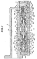
- a brake pressure control valve 10 according to the present invention.
- the valve 10 is integrated with a conventional tandem master cylinder 12.
- primary and secondary pistons are operatively disposed in a bore 12a of the cylinder 12, so that upon depression of a brake pedal (not shown), a master cylinder pressure P m is produced equally at its outlet ports 12b and 12c in a conventional manner.
- the brake pressure control valve 10 of the invention comprises an elongate housing 14 which is integrated with the body of the master cylinder 12. Within a straight bore 14a of the housing 14, there are mounted in tandem manner first and second proportioning valve units 16 and 16'. These two units 16 and 16' have identical constructions and are arranged coaxially and symmetrically to each other. Thus, the following description on the construction will be directed to only the first valve unit 16. The corresponding parts and portions of the second unit 16' are identified by the same reference numerals but with a prime.
- the valve unit 16 comprises a valve casing 18 sealingly disposed in the left half of the straight bore 14a.
- the valve casing 18 has therein a blind bore comprising aligned smaller and larger diameter bore portions 18a and 18b which are merged. Designated by references R and seal rings.
- a pressure control piston 20 is slidably disposed in the bore of the casing 18 with its largest diameter portion 20a sealingly received in the smaller diameter bore portion 18a of the casing 18. With this, an outlet chamber 22 is defined at the bottom of the bore portion 18a.
- a medium diameter portion 20b of the piston 20 is slidably and sealingly supported by both a holder 24 and a seal member 26 which are retained in the larger diameter bore portion 18b of the casing 18.
- the piston 20 has at its right end a smallest diameter portion 20c which is exposed to the larger diameter bore portion 18b.
- the piston 20 is further formed with an annular ridge 20d between the largest and medium diameter portions 20a and 20b, which is engageable with the holder 24 to limit the axial displacement of the piston 20 relative to the holder 24 to a value of L,.
- the piston 20 is formed with an axially extending through passage 20e which connects the outlet chamber 22 with the larger diameter bore portion 18b, and an annular valve seat 28 is removably mounted on the smallest diameter portion 20c.
- An annular hollow plug 30 is retained in the open end of the casing 18, and a free piston 32 is slidably and sealingly disposed in the hollow plug 30 with its enlarged portion 32a projected into the larger diameter bore portion 18b of the casing 18.
- the larger diameter bore portion 18b acts as an inlet chamber for the reason which will become clear hereinafter.
- the enlarged portion 32a is formed with a blind bore 32b which receives therein a portion of a valve body 34.
- the blind bore 32b is formed at its mouth portion with an inward projection (no numeral) to which a projection (no numeral) of the valve body 34 is engageable to suppress disconnection of the valve body 34 from the bore 32b.
- a coil spring 36 is compressed between the head of the valve body 34 and the enlarged portion 32a of the free piston 32 to bias the valve body 34 away from the free piston 32.
- the free piston 32 is formed thereon with an annular ridge 32c.
- Another coil spring 38 is compressed between the annular ridge 32c of the free piston 32 and the beforementioned valve seat 28 to bias them, that is, the free piston 32 and the piston 20 away from each other.
- a valve stem 40 extending from the valve body 34 passes through the through passage 20e of the piston 20 and is contactable at its leading end with the bottom of the blind bore 18a of the casing 18 under a certain condition which is illustrated.
- the casing 18 is formed with a wide annular groove 18c therearound which forms a chamber communicating with the outlet port 12c (or 12b) of the master cylinder 12.
- the valve casing 18 is formed at its radially opposed sides with inlet and outlet ports 18d and 18e which connect the chamber of the groove 18c with the larger diameter bore portion 18b (or inlet chamber).
- the chamber of the annular groove 18c connects with a first outlet port 14b which is formed in the housing 14 of the valve 10.
- the outlet port 12c (or 12b) of the master cylinder 12 is constantly communicated with the first outlet port 14b, so that the master cylinder pressure P m is directly applied to the first outlet port 14b irrespective of magnitude of the pressure P m .
- the valve casing 18 has near the bottom of the bore thereof another outlet port 18f which communicates the outlet chamber 22 with a second outlet port 14c which is formed in the housing 14 of the valve 10.
- valve seat 28 is a hollow member and has a mouth portion 28a at one end which faces the head of the valve body 34. If desired, the valve seat 28 may be screwed to the smallest diameter portion 20c of the piston 20 in order to facilitate connection and disconnection of the valve seat 28 with and from the piston 20.
- valve unit 16 (or 16') is assembled in the following manner:
- valve units 16 and 16' which have been assembled in the above-stated manner are assembled in the housing 14 in the following manner:
- the first outlet port 14b is connected to the left-side front wheel brake cylinder, the other first outlet port 14b' to the right-side front wheel brake cylinder, the second outlet port 14c to the right-side rear wheel brake cylinder and the other second outlet port 14c' to the left-side rear wheel brake cylinder.
- valve units 16 and 16' are in their rest or inoperative conditions.
- the head of the valve body 34 (or 34') is separated by the distance of L 3 from the valve seat 28 (or 28') thereby to communicate the inlet chamber 18b (or 18b') with the outlet chamber 22 (or 22') through the passage 20e (or 20e') of the piston 20 (or 20').
- the tandem master cylinder 12 produces master cylinder pressure P m at each of the outlet ports 12b and 12c thereof.
- the pressure P m is directly applied to both the front wheel brake cylinders as front wheel brake pressure P f through the constantly communicated inlet port 18d (or 18d'), inlet chamber 18b (18b'), outlet port 18e (or 18e') and first outlet port 14b (or 14b'), and thus brakes the front wheels.
- the front wheel brake pressure P f is always equal to the master cylinder pressure P m .
- the master cylinder pressure P m at the outlet port 12c (or 12b) is directly applied to both the rear wheel brake cylinders as rear wheel brake pressure P, through the inlet port 18d (or 18d'), the inlet chamber 18b (18b'), the mouth portion 28a (or 28a') of the valve seat 28 (28a'), the passage 20e (or 20e') of the piston 20 (or 20'), the outlet chamber 22 (or 22') and the second outlet port 14c (or 14c'), and thus brakes the rear wheels.
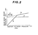
- the rear wheel brake pressure P r increases at the same rate as the master cylinder pressure P m , as is indicated by the line "a" in Fig. 2.
- the sectional area at the largest diameter portion 20a (or 20a') of the piston 20 (or 20') will be designated by S l , the sectional area of the medium diameter portion 20b (or 20b') by 5 2 , the sectional area of the mouth portion 28a (or 28') of the valve seat 28 (or 28') by S 3 which is smaller than S 2 , the sectional area of the passage 20e (20e') of the piston 20 (20') by S 4 , and the force generated by the spring 38 (or 38') by F.
- the force balance applied to the pistons 20 and 20' is explained by the following equation: That is, In the above equation (1), the left term represents the force which is applied to the pistons 20 and 20' in directions to bias them close to each other, while the right term represents the force which is applied to them in directions to bias them away from each other.
- valve seats 28 and 28' become in contact with the corresponding valve bodies 34 and 34', resulting in that the mouth portions 28a and 28a' of the valve seats 28 and 28' are closed.
- each valve unit 16 or 16' described above acts as a so-called proportioning valve.
- the master cylinder pressure P m is directly applied not only to the associated front wheel brake cylinder (left-side front wheel) but also to the associated rear wheel brake cylinder (right-side rear wheel) without carrying out the above-mentioned pressure control.
Landscapes
- Engineering & Computer Science (AREA)
- Transportation (AREA)
- Mechanical Engineering (AREA)
- Hydraulic Control Valves For Brake Systems (AREA)
Claims (5)
Applications Claiming Priority (4)
| Application Number | Priority Date | Filing Date | Title |
|---|---|---|---|
| JP186220/81 | 1981-11-20 | ||
| JP18622181A JPS5889449A (ja) | 1981-11-20 | 1981-11-20 | 液圧制御弁 |
| JP18622081A JPS5889448A (ja) | 1981-11-20 | 1981-11-20 | 2系統配管用液圧制御弁 |
| JP186221/81 | 1981-11-20 |
Publications (2)
| Publication Number | Publication Date |
|---|---|
| EP0080650A1 EP0080650A1 (de) | 1983-06-08 |
| EP0080650B1 true EP0080650B1 (de) | 1987-06-03 |
Family
ID=26503623
Family Applications (1)
| Application Number | Title | Priority Date | Filing Date |
|---|---|---|---|
| EP82110595A Expired EP0080650B1 (de) | 1981-11-20 | 1982-11-16 | Bremsdruck-Regelventil für ein Zweikreissystem |
Country Status (3)
| Country | Link |
|---|---|
| US (1) | US4571006A (de) |
| EP (1) | EP0080650B1 (de) |
| DE (1) | DE3276477D1 (de) |
Families Citing this family (2)
| Publication number | Priority date | Publication date | Assignee | Title |
|---|---|---|---|---|
| JPS58164461A (ja) * | 1982-03-23 | 1983-09-29 | Nissan Motor Co Ltd | 2系統液圧制御弁 |
| US4673220A (en) * | 1984-10-17 | 1987-06-16 | Sumitomo Electric Industries, Ltd. | Brake pressure control valve assembly having a bypass function |
Family Cites Families (13)
| Publication number | Priority date | Publication date | Assignee | Title |
|---|---|---|---|---|
| US3441318A (en) * | 1968-01-25 | 1969-04-29 | Wagner Electric Corp | Control valve |
| US3806200A (en) * | 1973-01-16 | 1974-04-23 | Bendix Corp | Brake proportioning valve with blend back |
| US3969000A (en) * | 1974-02-05 | 1976-07-13 | Tokico Ltd. | Brake hydraulic pressure control valve |
| DE2416574A1 (de) * | 1974-04-05 | 1975-10-16 | Alfred William Thomas | Zweikreis-bremsanlage fuer kraftfahrzeuge, bei der die hinterachsbremsen verschiedenen bremskreisen zugeordnet sind und die zwei druckminderer aufweist |
| JPS5526021B2 (de) * | 1974-05-02 | 1980-07-10 | ||
| JPS568781B2 (de) * | 1974-05-07 | 1981-02-25 | ||
| GB1523802A (en) * | 1975-05-06 | 1978-09-06 | Automotive Prod Co Ltd | Proportioning valve assemblies for split liquid pressure operated vehicle braking systems |
| JPS5386976A (en) * | 1977-01-12 | 1978-07-31 | Tokico Ltd | Brake liquid pressure controlling valve |
| US4154260A (en) * | 1977-03-10 | 1979-05-15 | The Bendix Corporation | Master cylinder having a proportioning and metering valve encapsulated in separate outlet ports |
| AU520749B2 (en) * | 1978-06-08 | 1982-02-25 | Brake And Clutch Industries Australia Pty. Ltd. | Brake pressure control valves |
| DE2915865A1 (de) * | 1979-04-19 | 1980-11-13 | Teves Gmbh Alfred | Zweikreisdruckregler |
| US4281880A (en) * | 1979-10-01 | 1981-08-04 | The Bendix Corporation | Back-to-back proportioning valve |
| DE3016207A1 (de) * | 1980-04-26 | 1981-10-29 | Alfred Teves Gmbh, 6000 Frankfurt | Bremsdrucksteuereinheit fuer eine hydraulische bremsanlage |
-
1982
- 1982-11-16 US US06/442,096 patent/US4571006A/en not_active Expired - Fee Related
- 1982-11-16 DE DE8282110595T patent/DE3276477D1/de not_active Expired
- 1982-11-16 EP EP82110595A patent/EP0080650B1/de not_active Expired
Also Published As
| Publication number | Publication date |
|---|---|
| DE3276477D1 (en) | 1987-07-09 |
| EP0080650A1 (de) | 1983-06-08 |
| US4571006A (en) | 1986-02-18 |
Similar Documents
| Publication | Publication Date | Title |
|---|---|---|
| US4421362A (en) | Anti-skid brake control system for wheeled vehicles | |
| US4422694A (en) | Braking pressure control unit for a hydraulic brake system | |
| US4053185A (en) | Dual braking correction device | |
| US4053186A (en) | Proportional valve apparatus for use in a rear brake system of a vehicle | |
| US4071281A (en) | Fluid pressure control device for crossed piping brake system | |
| US4477122A (en) | Hydraulic pressure control valve for automobile braking system | |
| US4184716A (en) | Control valve assembly for hydraulic brakes | |
| US4499729A (en) | Fast-fill master cylinder | |
| EP0089478B1 (de) | Bremsdruckregelventil für Zweikreisanlage | |
| GB2077869A (en) | Brake system for an automotive vehicle | |
| US4668021A (en) | Brake feel augmentation valve and system | |
| EP0080650A1 (de) | Bremsdruck-Regelventil für ein Zweikreissystem | |
| JPS6137133B2 (de) | ||
| US4669268A (en) | Master cylinder-reducing valve assembly | |
| EP0046659A1 (de) | Hydraulischer Betätigungszylinder für eine Fahrzeug-Innenbackenbremse | |
| US4385786A (en) | Hydraulic pressure control valve for a double piping braking system | |
| US4717208A (en) | Brake pressure control valve of a double piping hydraulic braking system | |
| US4437310A (en) | Tandem master cylinder with a pressure regulating valve for an automotive vehicle brake system | |
| US4214794A (en) | Brake pressure control apparatus for split braking system | |
| US4212501A (en) | Vehicular anti-skid brake device | |
| US4490978A (en) | Fluid pressure proportioners | |
| GB2087494A (en) | Hydraulic Pressure Control Valve for Dual Circuit Braking System | |
| US5174635A (en) | Hydraulic braking pressure control system for rear wheel brake | |
| US4444436A (en) | Hydraulic pressure control valve | |
| JPH0234813B2 (de) |
Legal Events
| Date | Code | Title | Description |
|---|---|---|---|
| PUAI | Public reference made under article 153(3) epc to a published international application that has entered the european phase |
Free format text: ORIGINAL CODE: 0009012 |
|
| 17P | Request for examination filed |
Effective date: 19821116 |
|
| AK | Designated contracting states |
Designated state(s): DE FR GB |
|
| RAP1 | Party data changed (applicant data changed or rights of an application transferred) |
Owner name: NIPPON AIR BRAKE CO., LTD. Owner name: NISSAN MOTOR CO., LTD. |
|
| GRAA | (expected) grant |
Free format text: ORIGINAL CODE: 0009210 |
|
| AK | Designated contracting states |
Kind code of ref document: B1 Designated state(s): DE FR GB |
|
| REF | Corresponds to: |
Ref document number: 3276477 Country of ref document: DE Date of ref document: 19870709 |
|
| ET | Fr: translation filed | ||
| PLBE | No opposition filed within time limit |
Free format text: ORIGINAL CODE: 0009261 |
|
| STAA | Information on the status of an ep patent application or granted ep patent |
Free format text: STATUS: NO OPPOSITION FILED WITHIN TIME LIMIT |
|
| 26N | No opposition filed | ||
| PGFP | Annual fee paid to national office [announced via postgrant information from national office to epo] |
Ref country code: GB Payment date: 19931108 Year of fee payment: 12 |
|
| PGFP | Annual fee paid to national office [announced via postgrant information from national office to epo] |
Ref country code: FR Payment date: 19931110 Year of fee payment: 12 Ref country code: DE Payment date: 19931110 Year of fee payment: 12 |
|
| PG25 | Lapsed in a contracting state [announced via postgrant information from national office to epo] |
Ref country code: GB Effective date: 19941116 |
|
| GBPC | Gb: european patent ceased through non-payment of renewal fee |
Effective date: 19941116 |
|
| PG25 | Lapsed in a contracting state [announced via postgrant information from national office to epo] |
Ref country code: FR Effective date: 19950731 |
|
| PG25 | Lapsed in a contracting state [announced via postgrant information from national office to epo] |
Ref country code: DE Effective date: 19950801 |
|
| REG | Reference to a national code |
Ref country code: FR Ref legal event code: ST |