EP0080722A2 - Coupleur optique pour câbles à fibres optiques - Google Patents
Coupleur optique pour câbles à fibres optiques Download PDFInfo
- Publication number
- EP0080722A2 EP0080722A2 EP82111005A EP82111005A EP0080722A2 EP 0080722 A2 EP0080722 A2 EP 0080722A2 EP 82111005 A EP82111005 A EP 82111005A EP 82111005 A EP82111005 A EP 82111005A EP 0080722 A2 EP0080722 A2 EP 0080722A2
- Authority
- EP
- European Patent Office
- Prior art keywords
- sleeve
- ferrules
- optical
- fiber cables
- optical connector
- Prior art date
- Legal status (The legal status is an assumption and is not a legal conclusion. Google has not performed a legal analysis and makes no representation as to the accuracy of the status listed.)
- Withdrawn
Links
- 239000013307 optical fiber Substances 0.000 title claims abstract description 33
- 230000003287 optical effect Effects 0.000 title claims abstract description 32
- 229920003002 synthetic resin Polymers 0.000 description 3
- 239000000057 synthetic resin Substances 0.000 description 3
- 238000000034 method Methods 0.000 description 2
- 238000010276 construction Methods 0.000 description 1
- 239000000463 material Substances 0.000 description 1
- 238000000465 moulding Methods 0.000 description 1
Images
Classifications
-
- G—PHYSICS
- G02—OPTICS
- G02B—OPTICAL ELEMENTS, SYSTEMS OR APPARATUS
- G02B6/00—Light guides; Structural details of arrangements comprising light guides and other optical elements, e.g. couplings
- G02B6/24—Coupling light guides
- G02B6/36—Mechanical coupling means
- G02B6/38—Mechanical coupling means having fibre to fibre mating means
- G02B6/3807—Dismountable connectors, i.e. comprising plugs
- G02B6/3873—Connectors using guide surfaces for aligning ferrule ends, e.g. tubes, sleeves, V-grooves, rods, pins, balls
- G02B6/3874—Connectors using guide surfaces for aligning ferrule ends, e.g. tubes, sleeves, V-grooves, rods, pins, balls using tubes, sleeves to align ferrules
-
- G—PHYSICS
- G02—OPTICS
- G02B—OPTICAL ELEMENTS, SYSTEMS OR APPARATUS
- G02B6/00—Light guides; Structural details of arrangements comprising light guides and other optical elements, e.g. couplings
- G02B6/24—Coupling light guides
- G02B6/36—Mechanical coupling means
- G02B6/38—Mechanical coupling means having fibre to fibre mating means
- G02B6/3807—Dismountable connectors, i.e. comprising plugs
- G02B6/381—Dismountable connectors, i.e. comprising plugs of the ferrule type, e.g. fibre ends embedded in ferrules, connecting a pair of fibres
-
- G—PHYSICS
- G02—OPTICS
- G02B—OPTICAL ELEMENTS, SYSTEMS OR APPARATUS
- G02B6/00—Light guides; Structural details of arrangements comprising light guides and other optical elements, e.g. couplings
- G02B6/24—Coupling light guides
- G02B6/36—Mechanical coupling means
- G02B6/38—Mechanical coupling means having fibre to fibre mating means
- G02B6/3807—Dismountable connectors, i.e. comprising plugs
- G02B6/3833—Details of mounting fibres in ferrules; Assembly methods; Manufacture
- G02B6/3867—Details of mounting fibres in ferrules; Assembly methods; Manufacture comprising air venting holes
Definitions
- the present invention relates to an optical connector for optical fiber cables.
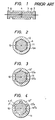
- One of known optical connectors for optical fiber cables has construction as shown in Fig. 1.
- This optical connector is arranged to insert ferrules 1 and 2, in which optical fibers 10 of optical fiber cables are located and held along the center lines of the ferrules 1 and 2, into a sleeve 3 from both ends of the sleeve 3 so that the ends of the ferrules 1 and 2 contact each other and to thereby connect the ends of the optical fibers.
- both optical fibers are accurately aligned with each other, i.e., they come accurately into a straightline.
- the outer surfaces of the ferrules 1 and 2 are accurately cylindrical and the optical fibers are located accurately on the center lines of the ferrules 1 and 2, the inner surface of the sleeve 3 is also accurately cylindrical and, when the ferrules 1 and 2 are inserted to the sleeve 3, the inner surface of the sleeve 3 contacts the outer surfaces of the ferrules 1 and 2 perfectly closely so that there occurs as far as possible no clearance between said inner surface and said outer surfaces.
- the above-mentioned optical connector has such disadvantage that the air in the sleeve 3 does not go out easily when inserting the ferrules 1 and 2 from both ends of the sleeve 3 and, consequently, the ferrules cannot be inserted smoothly.
- a small hole 4 may be provided to the sleeve 3 as shown by broken lines in Fig. 1 so that the air goes out through said small hole 4. Even when this method is adopted, it is still not easy to insert the ferrules to the sleeve because of friction between the inner surface of the sleeve and outer surfaces of the ferrules. Moreover, when the sleeve is to be made of synthetic resin, it is difficult to form a sleeve having such small hole.
- an optical connector for optical fiber cables comprising a sleeve having a longitudinal through hole and two ferrules which are to be inserted to said through hole from both ends of said sleeve and to serve for holding the ends of optical fibers of optical fiber cables, said optical connector for optical fiber cables being arranged that the inner surface of said sleeve contacts the outer surfaces of said ferrules by at least three straight lines which are parallel with and located at equal distance from the center line of said sleeve.
- FIG. 2 showing a cross sectional view of Embodiment 1 of the optical connector according to the present invention
- numeral 11 designates a ferrule, in which an optical fiber 10 is arranged at the center thereof and which is constructed to have a shape similar to that of the known optical connector shown in Fig. 1.
- Numeral 12 designates a sleeve having a through hole 12a, which is formed so that the cross sectional shape thereof becomes a hexagon,.
- the optical connector constructed as described in the above is arranged to connect the optical fibers of optical fiber cables by inserting both ferrules into the sleeve and thereby putting the ends of both ferrules into contact with each other in the same way as the known optical connector.
- respective ferrules of the optical connector according to the present invention are inserted to the sleeve in the state that the cylindrical outer surface of each ferrule contacts each surface of the hexagonal inner wall of the sleeve only by six straight lines which are in parallel with and located at equal distance from the center line of the sleeve and respective ferrules are thereby centered with each other and with the sleeve. Therefore, the air in the sleeve easily goes out through the spaces formed between the inner wall of the sleeve and outer surfaces of the ferrules (one of said spaces is represented by reference symbol A and Fig. 2).
- the cross sectional shape of the through hole of the sleeve is not limited to a hexagon.
- the shape of said cross section may be a regular triangle, square or any other regular polygon.
- Fig. 3 shows a cross sectional view of Embodiment 2 of the optical connector according to the present invention.
- the through hole 12'a of the sleeve 12' is arranged to have a cross sectional shape as shown in the figure, i.e., a modified hexagon each side of which is formed as an arc.
- This embodiment is thereby arranged that the inner wall of the sleeve and outer surfaces of the ferrules contact only by the straight lines which are in parallel with the center line of the sleeve (i.e., by the top portions of cylindrical convex surfaces 12'b of the inner wall of the sleeve).
- the inner wall of the sleeve and outer surfaces of the ferrules contact by straight lines when the ferrules are formed as bar-like members each having a cross sectional shape of regular polygon while the sleeve is formed to have a through hole with a circular cross section.
- Fig. 4 shows a cross sectional view of Embodiment 3 of the optical connector according to the present invention.
- grooves 12" a are formed on the inner surface of the sleeve 12" so that the grooves 12"a extend in parallel with the center line of the sleeve 12".
- the air in the sleeve 12" goes out through the grooves 12"a when the ferrules 11 are inserted to the sleeve 12".
- long and narrow surfaces 12"b which are formed between respective grooves 12"a of the sleeve 12" and which are in parallel with the center line of the sleeve 12" contact the outer surfaces of the ferrules and the ferrules are thereby positioned.
- the number of grooves 12"a is increased or the width t of each groove 12"a is made large, in case of this embodiment, it is possible to make the distance between respective grooves small so that the inner surface of the sleeve and outer surfaces of the ferrules contact by portions which are in parallel with the center line of the sleeve and which may be considefed substantially as straight lines. This enables to insert the ferrules to the sleeve more easily.
- the optical connector for optical fiber cables according to the present invention is arranged that the cross sectional shape of either the inner wall surface of the sleeve or outer surfaces of the ferrules is formed as a regular polygon or a shape similar to a regular polygon. Therefore, when inserting the ferrules to the sleeve, the air in the sleeve goes out easily and it does not become difficult to insert the ferrules because of the pressure of the air in the sleeve.
- the optical connector according to the present invention is arranged that the inner wall of the sleeve and outer surfaces of the ferrules contact at a plural number of places by portions which are parallel with the center line of the sleeve and which may be regarded substantially as straight lines, resistance to be caused by friction and the like when inserting the ferrules to the sleeve is extremely small. Therefore, even when the sleeve and ferrules are formed very accurately so that they reliably contact each other, it is possible to insert the ferrules to the sleeve quite easily.
- the sleeve and ferrules of the optical connector according to the present invention are arranged to have such shapes that enable to produce the sleeve and ferrules easily by molding work of synthetic resins, it is possible to produce the optical connector with extremely high accuracy by using synthetic resins as materials.
Landscapes
- Physics & Mathematics (AREA)
- General Physics & Mathematics (AREA)
- Optics & Photonics (AREA)
- Mechanical Coupling Of Light Guides (AREA)
Applications Claiming Priority (2)
| Application Number | Priority Date | Filing Date | Title |
|---|---|---|---|
| JP190897/81 | 1981-11-30 | ||
| JP56190897A JPS5893017A (ja) | 1981-11-30 | 1981-11-30 | 光コネクタ− |
Publications (2)
| Publication Number | Publication Date |
|---|---|
| EP0080722A2 true EP0080722A2 (fr) | 1983-06-08 |
| EP0080722A3 EP0080722A3 (fr) | 1986-06-11 |
Family
ID=16265537
Family Applications (1)
| Application Number | Title | Priority Date | Filing Date |
|---|---|---|---|
| EP82111005A Withdrawn EP0080722A3 (fr) | 1981-11-30 | 1982-11-29 | Coupleur optique pour câbles à fibres optiques |
Country Status (3)
| Country | Link |
|---|---|
| US (1) | US4636034A (fr) |
| EP (1) | EP0080722A3 (fr) |
| JP (1) | JPS5893017A (fr) |
Cited By (7)
| Publication number | Priority date | Publication date | Assignee | Title |
|---|---|---|---|---|
| EP0253426A1 (fr) * | 1986-07-16 | 1988-01-20 | Koninklijke Philips Electronics N.V. | Connecteur pour une connexion détachable de fibres optiques |
| EP0543094A1 (fr) * | 1991-11-20 | 1993-05-26 | Kyocera Corporation | Manchon d'alignement céramique moulé pour connecteur à fibre optique et procédé de fabrication |
| US5239603A (en) * | 1991-06-12 | 1993-08-24 | Kyocera Corporation | Integrally-molded ceramic alignment sleeve for optical fiber connector and method of producing the same |
| EP0718651A3 (fr) * | 1994-12-22 | 1996-12-04 | At & T Corp | Manchon d'alignement fermé pour connecteurs optiques |
| WO2002031559A1 (fr) * | 2000-10-13 | 2002-04-18 | Kyousei Cystem. Co, Ltd. | Composant de connecteur optique, sa structure a matrices, et procede de fabrication |
| WO2003052480A1 (fr) * | 2001-12-19 | 2003-06-26 | Sumitomo Electric Industries, Ltd. | Manchon de connexion optique, module optique, et module de communication optique |
| WO2003052479A1 (fr) * | 2001-12-19 | 2003-06-26 | Sumitomo Electric Industries, Ltd. | Manchon de connexion optique, module optique, et module de communication optique |
Families Citing this family (14)
| Publication number | Priority date | Publication date | Assignee | Title |
|---|---|---|---|---|
| JPS61126211U (fr) * | 1985-01-25 | 1986-08-08 | ||
| JPS6287306U (fr) * | 1985-11-21 | 1987-06-04 | ||
| US4815810A (en) * | 1988-01-11 | 1989-03-28 | Gte Products Corporation | Housing for a fiber optic component |
| CA1321089C (fr) * | 1988-05-06 | 1993-08-10 | Adc Telecommunications, Inc. | Commutateur optique |
| US5179607A (en) * | 1991-07-15 | 1993-01-12 | Forss, Inc. | Fluted, high efficiency fiber optic adapter |
| CA2133230C (fr) * | 1993-09-30 | 2004-06-29 | Hiromi Kurashima | Module optique; methode de sa fabrication et manchon |
| JP2776312B2 (ja) * | 1995-07-21 | 1998-07-16 | 日本電気株式会社 | 光モジュール装置及び光コネクタ接続装置 |
| JP3132998B2 (ja) * | 1996-07-09 | 2001-02-05 | セイコーインスツルメンツ株式会社 | 光コネクタ用フェルール |
| JP4435658B2 (ja) * | 2004-09-15 | 2010-03-24 | 株式会社アドバンテスト | 光コネクタ清掃方法、清掃治具、清掃治具ユニット、及び光コネクタ |
| JP4523874B2 (ja) * | 2005-06-01 | 2010-08-11 | ホシデン株式会社 | 光コネクタ |
| JP6775783B2 (ja) * | 2017-09-21 | 2020-10-28 | 矢崎総業株式会社 | 光コネクタ装置 |
| PT3686638T (pt) * | 2017-09-21 | 2022-10-06 | Yazaki Corp | Dispositivo de conector ótico |
| CN111239947A (zh) * | 2020-03-22 | 2020-06-05 | 苏州专创光电科技有限公司 | 一种5g网络用通信光缆及光电复合缆及其制造方法 |
| CN112714882B (zh) * | 2020-03-22 | 2021-11-26 | 天一线缆邯郸有限公司 | 一种5g网络用通信光缆及光电复合缆及其制造方法 |
Family Cites Families (7)
| Publication number | Priority date | Publication date | Assignee | Title |
|---|---|---|---|---|
| GB1450760A (en) * | 1975-06-24 | 1976-09-29 | Standard Telephones Cables Ltd | Optical fibre multiway connector |
| US4193665A (en) * | 1976-03-01 | 1980-03-18 | International Telephone And Telegraph Corporation | Fiber optic contact alignment device |
| GB1556476A (en) * | 1976-10-07 | 1979-11-28 | Standard Telephones Cables Ltd | Fibre connector |
| CA1093873A (fr) * | 1978-06-05 | 1981-01-20 | Helmut H. Lukas | Traduction non-disponible |
| JPS554043A (en) * | 1978-06-26 | 1980-01-12 | Nippon Telegr & Teleph Corp <Ntt> | Optical connector |
| US4257674A (en) * | 1979-04-23 | 1981-03-24 | Gte Products Corporation | Elastomeric fiber optic splice |
| FR2479483A1 (fr) * | 1980-03-25 | 1981-10-02 | Socapex | Manchon d'accouplement de connecteur pour monofibre optique, et connecteur muni d'un tel manchon |
-
1981
- 1981-11-30 JP JP56190897A patent/JPS5893017A/ja active Pending
-
1982
- 1982-11-29 EP EP82111005A patent/EP0080722A3/fr not_active Withdrawn
-
1985
- 1985-04-04 US US06/719,046 patent/US4636034A/en not_active Expired - Lifetime
Cited By (8)
| Publication number | Priority date | Publication date | Assignee | Title |
|---|---|---|---|---|
| EP0253426A1 (fr) * | 1986-07-16 | 1988-01-20 | Koninklijke Philips Electronics N.V. | Connecteur pour une connexion détachable de fibres optiques |
| US5239603A (en) * | 1991-06-12 | 1993-08-24 | Kyocera Corporation | Integrally-molded ceramic alignment sleeve for optical fiber connector and method of producing the same |
| EP0543094A1 (fr) * | 1991-11-20 | 1993-05-26 | Kyocera Corporation | Manchon d'alignement céramique moulé pour connecteur à fibre optique et procédé de fabrication |
| EP0718651A3 (fr) * | 1994-12-22 | 1996-12-04 | At & T Corp | Manchon d'alignement fermé pour connecteurs optiques |
| WO2002031559A1 (fr) * | 2000-10-13 | 2002-04-18 | Kyousei Cystem. Co, Ltd. | Composant de connecteur optique, sa structure a matrices, et procede de fabrication |
| WO2003052480A1 (fr) * | 2001-12-19 | 2003-06-26 | Sumitomo Electric Industries, Ltd. | Manchon de connexion optique, module optique, et module de communication optique |
| WO2003052479A1 (fr) * | 2001-12-19 | 2003-06-26 | Sumitomo Electric Industries, Ltd. | Manchon de connexion optique, module optique, et module de communication optique |
| US6893163B2 (en) | 2001-12-19 | 2005-05-17 | Sumitomo Electric Industries, Ltd. | Optical connection sleeve, optical module and optical communication module |
Also Published As
| Publication number | Publication date |
|---|---|
| EP0080722A3 (fr) | 1986-06-11 |
| JPS5893017A (ja) | 1983-06-02 |
| US4636034A (en) | 1987-01-13 |
Similar Documents
| Publication | Publication Date | Title |
|---|---|---|
| EP0080722A2 (fr) | Coupleur optique pour câbles à fibres optiques | |
| US4312564A (en) | Multi-fiber optic connector | |
| US4779952A (en) | Optical connector | |
| US5926596A (en) | Overmolded alignment ferrule | |
| US4140365A (en) | Fiber optic cable connector housing | |
| US4140367A (en) | Multiple channel connector for fiber optic cables | |
| US6069992A (en) | Connector system with precision alignment | |
| CA2018495C (fr) | Connecteur a fibres optiques et adaptateur connexe | |
| US4208095A (en) | Connector for an optical monofibre | |
| US4339172A (en) | Connector having a single segmented deformable grip member for optical cables | |
| US4506946A (en) | Optic fiber coupling guide, method of making the same and method of use | |
| EP0125398A1 (fr) | Connecteur de fibre-optique | |
| GB2148536A (en) | Optical fibre connector | |
| GB1564292A (en) | Fibre optic connector assembly | |
| CA2077355A1 (fr) | Connecteur de fibres optiques groupees | |
| US4676589A (en) | Optical fiber coupler for connecting two optical cables in alignment | |
| US6616462B2 (en) | Convertible multi-diameter sleeve for optical fiber connectors | |
| EP0015291B1 (fr) | Piece de raccordement pour fibres optiques | |
| US4161347A (en) | Connector for an optical fibre link | |
| GB1563077A (en) | Connector for light conductive cables | |
| ITMI940594A1 (it) | Elemento di interconnessione per cavi multifibra | |
| KR19980032688A (ko) | 광섬유 커넥터 | |
| US6210045B1 (en) | Alignment sleeve for aligning ferrules and associated assembly method | |
| EP0730175B1 (fr) | Connecteur optique | |
| CA1178095A (fr) | Guide de connexion de fibres optiques |
Legal Events
| Date | Code | Title | Description |
|---|---|---|---|
| PUAI | Public reference made under article 153(3) epc to a published international application that has entered the european phase |
Free format text: ORIGINAL CODE: 0009012 |
|
| AK | Designated contracting states |
Designated state(s): DE FR GB NL |
|
| 17P | Request for examination filed |
Effective date: 19830922 |
|
| PUAL | Search report despatched |
Free format text: ORIGINAL CODE: 0009013 |
|
| AK | Designated contracting states |
Kind code of ref document: A3 Designated state(s): DE FR GB NL |
|
| 17Q | First examination report despatched |
Effective date: 19880322 |
|
| STAA | Information on the status of an ep patent application or granted ep patent |
Free format text: STATUS: THE APPLICATION IS DEEMED TO BE WITHDRAWN |
|
| 18D | Application deemed to be withdrawn |
Effective date: 19880902 |
|
| RIN1 | Information on inventor provided before grant (corrected) |
Inventor name: SAITOH, HIROAKI Inventor name: KASHIMURA, NORITAKE |