EP0080734A2 - Vanne pour bouteilles à gaz combustible - Google Patents
Vanne pour bouteilles à gaz combustible Download PDFInfo
- Publication number
- EP0080734A2 EP0080734A2 EP82111046A EP82111046A EP0080734A2 EP 0080734 A2 EP0080734 A2 EP 0080734A2 EP 82111046 A EP82111046 A EP 82111046A EP 82111046 A EP82111046 A EP 82111046A EP 0080734 A2 EP0080734 A2 EP 0080734A2
- Authority
- EP
- European Patent Office
- Prior art keywords
- valve
- gas
- canal
- regulator
- dwg
- Prior art date
- Legal status (The legal status is an assumption and is not a legal conclusion. Google has not performed a legal analysis and makes no representation as to the accuracy of the status listed.)
- Granted
Links
Images



Classifications
-
- F—MECHANICAL ENGINEERING; LIGHTING; HEATING; WEAPONS; BLASTING
- F17—STORING OR DISTRIBUTING GASES OR LIQUIDS
- F17C—VESSELS FOR CONTAINING OR STORING COMPRESSED, LIQUEFIED OR SOLIDIFIED GASES; FIXED-CAPACITY GAS-HOLDERS; FILLING VESSELS WITH, OR DISCHARGING FROM VESSELS, COMPRESSED, LIQUEFIED, OR SOLIDIFIED GASES
- F17C13/00—Details of vessels or of the filling or discharging of vessels
- F17C13/002—Details of vessels or of the filling or discharging of vessels for vessels under pressure
-
- F—MECHANICAL ENGINEERING; LIGHTING; HEATING; WEAPONS; BLASTING
- F17—STORING OR DISTRIBUTING GASES OR LIQUIDS
- F17C—VESSELS FOR CONTAINING OR STORING COMPRESSED, LIQUEFIED OR SOLIDIFIED GASES; FIXED-CAPACITY GAS-HOLDERS; FILLING VESSELS WITH, OR DISCHARGING FROM VESSELS, COMPRESSED, LIQUEFIED, OR SOLIDIFIED GASES
- F17C13/00—Details of vessels or of the filling or discharging of vessels
- F17C13/04—Arrangement or mounting of valves
-
- F—MECHANICAL ENGINEERING; LIGHTING; HEATING; WEAPONS; BLASTING
- F17—STORING OR DISTRIBUTING GASES OR LIQUIDS
- F17C—VESSELS FOR CONTAINING OR STORING COMPRESSED, LIQUEFIED OR SOLIDIFIED GASES; FIXED-CAPACITY GAS-HOLDERS; FILLING VESSELS WITH, OR DISCHARGING FROM VESSELS, COMPRESSED, LIQUEFIED, OR SOLIDIFIED GASES
- F17C2201/00—Vessel construction, in particular geometry, arrangement or size
- F17C2201/01—Shape
- F17C2201/0104—Shape cylindrical
- F17C2201/0109—Shape cylindrical with exteriorly curved end-piece
-
- F—MECHANICAL ENGINEERING; LIGHTING; HEATING; WEAPONS; BLASTING
- F17—STORING OR DISTRIBUTING GASES OR LIQUIDS
- F17C—VESSELS FOR CONTAINING OR STORING COMPRESSED, LIQUEFIED OR SOLIDIFIED GASES; FIXED-CAPACITY GAS-HOLDERS; FILLING VESSELS WITH, OR DISCHARGING FROM VESSELS, COMPRESSED, LIQUEFIED, OR SOLIDIFIED GASES
- F17C2201/00—Vessel construction, in particular geometry, arrangement or size
- F17C2201/01—Shape
- F17C2201/0104—Shape cylindrical
- F17C2201/0119—Shape cylindrical with flat end-piece
-
- F—MECHANICAL ENGINEERING; LIGHTING; HEATING; WEAPONS; BLASTING
- F17—STORING OR DISTRIBUTING GASES OR LIQUIDS
- F17C—VESSELS FOR CONTAINING OR STORING COMPRESSED, LIQUEFIED OR SOLIDIFIED GASES; FIXED-CAPACITY GAS-HOLDERS; FILLING VESSELS WITH, OR DISCHARGING FROM VESSELS, COMPRESSED, LIQUEFIED, OR SOLIDIFIED GASES
- F17C2201/00—Vessel construction, in particular geometry, arrangement or size
- F17C2201/03—Orientation
- F17C2201/032—Orientation with substantially vertical main axis
-
- F—MECHANICAL ENGINEERING; LIGHTING; HEATING; WEAPONS; BLASTING
- F17—STORING OR DISTRIBUTING GASES OR LIQUIDS
- F17C—VESSELS FOR CONTAINING OR STORING COMPRESSED, LIQUEFIED OR SOLIDIFIED GASES; FIXED-CAPACITY GAS-HOLDERS; FILLING VESSELS WITH, OR DISCHARGING FROM VESSELS, COMPRESSED, LIQUEFIED, OR SOLIDIFIED GASES
- F17C2205/00—Vessel construction, in particular mounting arrangements, attachments or identifications means
- F17C2205/01—Mounting arrangements
- F17C2205/0153—Details of mounting arrangements
- F17C2205/018—Supporting feet
-
- F—MECHANICAL ENGINEERING; LIGHTING; HEATING; WEAPONS; BLASTING
- F17—STORING OR DISTRIBUTING GASES OR LIQUIDS
- F17C—VESSELS FOR CONTAINING OR STORING COMPRESSED, LIQUEFIED OR SOLIDIFIED GASES; FIXED-CAPACITY GAS-HOLDERS; FILLING VESSELS WITH, OR DISCHARGING FROM VESSELS, COMPRESSED, LIQUEFIED, OR SOLIDIFIED GASES
- F17C2205/00—Vessel construction, in particular mounting arrangements, attachments or identifications means
- F17C2205/03—Fluid connections, filters, valves, closure means or other attachments
- F17C2205/0302—Fittings, valves, filters, or components in connection with the gas storage device
- F17C2205/0338—Pressure regulators
-
- F—MECHANICAL ENGINEERING; LIGHTING; HEATING; WEAPONS; BLASTING
- F17—STORING OR DISTRIBUTING GASES OR LIQUIDS
- F17C—VESSELS FOR CONTAINING OR STORING COMPRESSED, LIQUEFIED OR SOLIDIFIED GASES; FIXED-CAPACITY GAS-HOLDERS; FILLING VESSELS WITH, OR DISCHARGING FROM VESSELS, COMPRESSED, LIQUEFIED, OR SOLIDIFIED GASES
- F17C2205/00—Vessel construction, in particular mounting arrangements, attachments or identifications means
- F17C2205/03—Fluid connections, filters, valves, closure means or other attachments
- F17C2205/0302—Fittings, valves, filters, or components in connection with the gas storage device
- F17C2205/0382—Constructional details of valves, regulators
-
- F—MECHANICAL ENGINEERING; LIGHTING; HEATING; WEAPONS; BLASTING
- F17—STORING OR DISTRIBUTING GASES OR LIQUIDS
- F17C—VESSELS FOR CONTAINING OR STORING COMPRESSED, LIQUEFIED OR SOLIDIFIED GASES; FIXED-CAPACITY GAS-HOLDERS; FILLING VESSELS WITH, OR DISCHARGING FROM VESSELS, COMPRESSED, LIQUEFIED, OR SOLIDIFIED GASES
- F17C2223/00—Handled fluid before transfer, i.e. state of fluid when stored in the vessel or before transfer from the vessel
- F17C2223/01—Handled fluid before transfer, i.e. state of fluid when stored in the vessel or before transfer from the vessel characterised by the phase
- F17C2223/0146—Two-phase
- F17C2223/0153—Liquefied gas, e.g. LPG, GPL
Definitions
- the fuel gases existing at present in the market are supplied to the consumers under one of the two following physical states:
- the above mentioned containers are, generally, cylindrical steel bottles, commonly named “gas cylinders” or “gas bottles”.
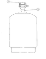
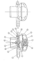
- valve a component part 1 ( D wg. No. 1) named "valve”, which is generally threaded in the upper part of the cylinder.
- This component part owing to its characteristics and through an adequate operation allows to establish a communication between inside and outside of the cylinder, allowing thus both the gas inlet into the cylinder (filling) and the gas outlet from the cylinder (consumption).
- the part 1 (Dwg. No. 1) performs in full its function in the cylinder filling operation, but it is not enough to permit the normal consumption of the gas contained in the cylinder. This happens because the gas is not generally consumed at the pressure at which it is liquefied into the cylinder.
- pressure regulator 2 (Dwg. No. 1) which is adjustable to the “valve” and receives through it the gas coming from the cylinder reducing its pressure to the values required by legal rules existing for the consumption of liquefied fuel gases.
- valve it is convenient to emphasize that what will be exposed next is referring to “self-closing” valves and therefore it will not be of interest to refer here to “manual-closing” valves, as our invention is mainly useful in “self-closing” valves although it can be used too in “manual-closing” valves.
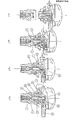
- the fig. 1 shows the two parts of the system in position before connection.
- the regulator was introduced in the upper part of the valve and the regulator inlet connection 11 can be seen introduced at the valve outlet canal 2 passing through the connection joint 6 but the clamping system has not yet reached the final security position.
- valves known has a canal 2 allowing the passage between the interior and exterior of the cylinder. This canal allows the cylinder to be filled with gas and it is also suitable (in the inverse direction) for the gas outlet for consumption.
- the referred canal diameter which varies according to the manufacturer, is usually of 6 to 8 mm.
- This diameter has to be of this size so that the cylinder filling is made quickly (15 to 20 seconds) in order that the filling plants are profitable.
- the discharge capacity of this canal is very excessive in respect of the normal consumption requirements, as the average consumer would consume a cylinder content within 15 to 20 days.
- the relation between the filling speed and the normal consumption speed in the referred canal assuming that the useful time of utilization is 10% of total time to empty a cylinder (15 days) at the consumer home, will be:
- valve outlet canal diameter to guarantee the normal consumption gas flow is sized between 1.2 and 1.8 mm for cylinders internal pressures of 7 k g/cm 2 and 0.5 kg/cm 2 respectively.
- the inlet and outlet canal 2 (Dwg. No. 1) existing in the conventional valves has the suitable diameter for a quick filling, but it is very excessive for the consumption.
- a gas leak can occur more easily during the consumption because larger diameters have to be used in the valve-regulator connection than those really necessary.
- valve can stop guaranteeing a good gas sealing and cause danger situations and fuel gas losses.
- valves are self-clos - ing type, these systems would be useless if it there would be smaller sections in the connecting area, what would reduce, as it can be seen in the Table I (Capsula System), the total ejection force exerted in the regulator to insufficient values to eject it.
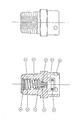
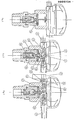
- the valve is composed as shown on Dwg. No. 6 and the components are as follows:
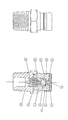
- the regulator is composed as shown on Dwg. No. 7 in gas closed position.
- the components are as follows:
- valve is threaded in the cylinder upper part and it is submitted to filling operation without the parts 29 and 30 (fig. 1 - Dwg. No. 8). In this stage the ball 28 is actuated by the spring 34 against the seat 33.
- a device 54 (Dwg. No. 8) specially studied for that purpose which is connected to the high pressure gas line.
- the gas under pressure will pass into the canal 31 forcing the ball 28 to come down. Then the gas will pass between the seat 33 and the ball 28 to inside of the cylinder.
- the parts 29 and 30 are introduced in the upper part of the valve by means of a special device 55 (Dwg. No. 8) which effects not only this introduction but also clips firmly part 30 in the groove 53 existing in part 27 guaranteeing thus the complete tightness and inviolability of the gas cylinder.
- a special device 55 Dwg. No. 8 which effects not only this introduction but also clips firmly part 30 in the groove 53 existing in part 27 guaranteeing thus the complete tightness and inviolability of the gas cylinder.
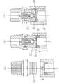
- the part 30 being made in brass-sheet and having a central hole 56 and the part 29 (see Dwg. Nos. 6 and 9) being designed with a special shape are allowing the introduction through them of the regulator gas inlet connection 36, which will be adjusted in the internal orifice of part 29 (2.5 mm diameter) as shown on Dwg. No. 9.
- the cylinder is sent to the consumption place where the pressure regulator is adjusted to it (see Dwg. No. 9).
- the needle-shaped gas inlet connection 36 with an outside diameter of 2,5 mm will be piercing (fig. 2) in the center of the part 29 through the hole 56 existing at the center of part 30 and it will be introduced in the referred part, jointing closely, in order to guarantee a good gas sealing between parts 29 and 36.
- the gas will pass then up to the regulator chamber 51 but it will not reach the outlet canal 38 because the gas on-off system composed of parts 37, 46, 47, 48, 49, 50 and 52 is in the most advanced position, closing the chamber 51 owing to the action of spring 49 (fig. 2).
- the on-off plunger 47 will be maintained at its most backward position by the gas pressure action in chamber 51 which actuates on the forward surface of on-off plunger.
- the two O-Rings 48 are operating now as piston rings.
- the consumer will remove the regulator from the valve and will send the cylinder with the valve to the filling plant.
- the filling plant must remove the parts 29 and 30 from the valve so that the system comes back to the same position as indicated in 5.2.1 and according to fig. 1 (Dwg. No. 8).
- the parts removal operation is named "decapsulation”.
- the part 29 is made in synthetic rubber and its sizes studied in such a way that, when exerting a compression with a specially designed device 57 (Dwg. No. 10) at its top the volume of the rubber contained between the parts 27 and 30 flows hydraulically to the periphery exerting an adequate force in the interior surface of the "capsula” 30 to extract it from the groove 53 (fig. 2 - Dwg. No. 10).
- a specially designed device 57 Dwg. No. 10
- the parts 29 and 30 are then removed from the top of part 27 and they must be scraped.
- the valve will be now in conditions to allow a new filling operation and then a new cycle can start.
Landscapes
- Engineering & Computer Science (AREA)
- Mechanical Engineering (AREA)
- General Engineering & Computer Science (AREA)
- Filling Or Discharging Of Gas Storage Vessels (AREA)
Applications Claiming Priority (4)
| Application Number | Priority Date | Filing Date | Title |
|---|---|---|---|
| PT74059 | 1981-11-30 | ||
| PT7405981A PT74059B (fr) | 1981-11-30 | 1981-11-30 | Regulateur de pression pour des recipients ou des bouteilles a gaz combustible |
| PT74058 | 1981-11-30 | ||
| PT7405881A PT74058B (fr) | 1981-11-30 | 1981-11-30 | Valvule pour des recipients ou des bouteilles a gaz combustible |
Publications (3)
| Publication Number | Publication Date |
|---|---|
| EP0080734A2 true EP0080734A2 (fr) | 1983-06-08 |
| EP0080734A3 EP0080734A3 (en) | 1984-05-23 |
| EP0080734B1 EP0080734B1 (fr) | 1987-02-25 |
Family
ID=26653433
Family Applications (1)
| Application Number | Title | Priority Date | Filing Date |
|---|---|---|---|
| EP19820111046 Expired EP0080734B1 (fr) | 1981-11-30 | 1982-11-30 | Vanne pour bouteilles à gaz combustible |
Country Status (4)
| Country | Link |
|---|---|
| EP (1) | EP0080734B1 (fr) |
| DE (1) | DE3275480D1 (fr) |
| DK (1) | DK530182A (fr) |
| ES (1) | ES517724A0 (fr) |
Cited By (1)
| Publication number | Priority date | Publication date | Assignee | Title |
|---|---|---|---|---|
| US20100243681A1 (en) * | 2007-09-28 | 2010-09-30 | Ryouhei Abe | Pressurized-fluid control mechanism and pressurized-fluid supply device |
Families Citing this family (1)
| Publication number | Priority date | Publication date | Assignee | Title |
|---|---|---|---|---|
| US7655932B2 (en) * | 2007-01-11 | 2010-02-02 | Varian Semiconductor Equipment Associates, Inc. | Techniques for providing ion source feed materials |
Family Cites Families (4)
| Publication number | Priority date | Publication date | Assignee | Title |
|---|---|---|---|---|
| FR1074398A (fr) * | 1953-04-08 | 1954-10-05 | Symbia Lab | Procédé et dispositif de remplissage, obturation et vidange d'un récipient contenant un fluide sous pression |
| DE6944693U (de) * | 1968-11-19 | 1970-03-12 | Giuseppe Mariani | Verschluss fuer mit fluessiggas gefuellte gasflaschen |
| FR2050851A5 (en) * | 1969-06-26 | 1971-04-02 | Pingeot Bardin Ets | Pressure reducing valve for gas cylinder - neck mounting |
| GB1529684A (en) * | 1974-12-19 | 1978-10-25 | Taymar Ltd | Adaptors |
-
1982
- 1982-11-26 ES ES517724A patent/ES517724A0/es active Granted
- 1982-11-29 DK DK530182A patent/DK530182A/da not_active Application Discontinuation
- 1982-11-30 DE DE8282111046T patent/DE3275480D1/de not_active Expired
- 1982-11-30 EP EP19820111046 patent/EP0080734B1/fr not_active Expired
Cited By (1)
| Publication number | Priority date | Publication date | Assignee | Title |
|---|---|---|---|---|
| US20100243681A1 (en) * | 2007-09-28 | 2010-09-30 | Ryouhei Abe | Pressurized-fluid control mechanism and pressurized-fluid supply device |
Also Published As
| Publication number | Publication date |
|---|---|
| ES8401789A1 (es) | 1984-01-01 |
| ES517724A0 (es) | 1984-01-01 |
| EP0080734B1 (fr) | 1987-02-25 |
| DE3275480D1 (en) | 1987-04-02 |
| DK530182A (da) | 1983-05-31 |
| EP0080734A3 (en) | 1984-05-23 |
Similar Documents
| Publication | Publication Date | Title |
|---|---|---|
| CA2432393C (fr) | Appareil et procede destines a l'insertion d'un liquide dans un systeme pressurise | |
| US4850387A (en) | Liquid dispensing valve | |
| US2172311A (en) | Valved tap plug | |
| US5467798A (en) | Refill-preventing valve for non-refillable containers | |
| MY134777A (en) | Drink dispenser assembly and container for drink, in particular carbonated drink, and drink dispensing line for use in such an assembly | |
| NO994975L (no) | Fremgangsmåte og fyllapparat for fylling av en utmatningsbeholder | |
| EP0080734A2 (fr) | Vanne pour bouteilles à gaz combustible | |
| US11261983B2 (en) | Safety valve | |
| EP2390589A1 (fr) | Dispositif de distribution et dispositif d'adaptateur de distribution associé | |
| US5960841A (en) | Filling yoke for compressed gas cylinders | |
| US6729348B1 (en) | Coupling assembly for petroleum liquefied gas with quick fastening automatic disconnection and retention and relief valve | |
| US5079962A (en) | Mating core probe valve and retainer | |
| US4510964A (en) | Valve for pressurized cylinders for liquified gas | |
| US3840056A (en) | Apparatus for filling liquid storage tanks | |
| US1974254A (en) | Discharge head for fluid containers | |
| EP0068794A2 (fr) | Distribution sélective de gaz | |
| US3684132A (en) | Disposable liquefied gas container and burner outlet fitting therefor | |
| US5213144A (en) | Valve opening device | |
| US7182108B2 (en) | Automatic bleed valve for pressurized system | |
| GB2085567A (en) | Fluid closure and discharge devices | |
| US3756277A (en) | Single cycle filler and dispensing valve | |
| JPS58160671A (ja) | 燃料ガスシリンダ用弁 | |
| US2408912A (en) | Fitting | |
| SU1125185A1 (ru) | Емкость дл транспортировки и выдачи жидких продуктов | |
| NZ198568A (en) | Fire extinguisher with positively frangible diaphragm |
Legal Events
| Date | Code | Title | Description |
|---|---|---|---|
| PUAI | Public reference made under article 153(3) epc to a published international application that has entered the european phase |
Free format text: ORIGINAL CODE: 0009012 |
|
| AK | Designated contracting states |
Designated state(s): DE FR GB IT |
|
| PUAL | Search report despatched |
Free format text: ORIGINAL CODE: 0009013 |
|
| AK | Designated contracting states |
Designated state(s): DE FR GB IT |
|
| 17P | Request for examination filed |
Effective date: 19840824 |
|
| GRAA | (expected) grant |
Free format text: ORIGINAL CODE: 0009210 |
|
| AK | Designated contracting states |
Kind code of ref document: B1 Designated state(s): DE FR GB IT |
|
| ITF | It: translation for a ep patent filed | ||
| REF | Corresponds to: |
Ref document number: 3275480 Country of ref document: DE Date of ref document: 19870402 |
|
| ET | Fr: translation filed | ||
| PLBE | No opposition filed within time limit |
Free format text: ORIGINAL CODE: 0009261 |
|
| STAA | Information on the status of an ep patent application or granted ep patent |
Free format text: STATUS: NO OPPOSITION FILED WITHIN TIME LIMIT |
|
| 26N | No opposition filed | ||
| PGFP | Annual fee paid to national office [announced via postgrant information from national office to epo] |
Ref country code: GB Payment date: 19911122 Year of fee payment: 10 Ref country code: DE Payment date: 19911122 Year of fee payment: 10 |
|
| PGFP | Annual fee paid to national office [announced via postgrant information from national office to epo] |
Ref country code: FR Payment date: 19911129 Year of fee payment: 10 |
|
| ITTA | It: last paid annual fee | ||
| PG25 | Lapsed in a contracting state [announced via postgrant information from national office to epo] |
Ref country code: GB Effective date: 19921130 |
|
| GBPC | Gb: european patent ceased through non-payment of renewal fee |
Effective date: 19921130 |
|
| PG25 | Lapsed in a contracting state [announced via postgrant information from national office to epo] |
Ref country code: FR Effective date: 19930730 |
|
| PG25 | Lapsed in a contracting state [announced via postgrant information from national office to epo] |
Ref country code: DE Effective date: 19930803 |
|
| REG | Reference to a national code |
Ref country code: FR Ref legal event code: ST |