EP0080773A2 - Broyeur à chambre pressurisé - Google Patents
Broyeur à chambre pressurisé Download PDFInfo
- Publication number
- EP0080773A2 EP0080773A2 EP82201499A EP82201499A EP0080773A2 EP 0080773 A2 EP0080773 A2 EP 0080773A2 EP 82201499 A EP82201499 A EP 82201499A EP 82201499 A EP82201499 A EP 82201499A EP 0080773 A2 EP0080773 A2 EP 0080773A2
- Authority
- EP
- European Patent Office
- Prior art keywords
- chamber
- grinder
- grinding
- pressure
- gas
- Prior art date
- Legal status (The legal status is an assumption and is not a legal conclusion. Google has not performed a legal analysis and makes no representation as to the accuracy of the status listed.)
- Granted
Links
Images

Classifications
-
- B—PERFORMING OPERATIONS; TRANSPORTING
- B02—CRUSHING, PULVERISING, OR DISINTEGRATING; PREPARATORY TREATMENT OF GRAIN FOR MILLING
- B02C—CRUSHING, PULVERISING, OR DISINTEGRATING IN GENERAL; MILLING GRAIN
- B02C19/00—Other disintegrating devices or methods
- B02C19/06—Jet mills
- B02C19/065—Jet mills of the opposed-jet type
Definitions
- the present invention is concerned with a pressure-chamber grinder in which the material to be ground, such as talc, bolus, titanium oxide, or soot, is ground to ultra-fine-grain particles by means of grinding gas.
- the grinder comprises a grinder chamber of substantially circular section, and the chamber is provided with a feed opening for the material to be ground, fed as a gas-tight plug, as well as with tangentially directed nozzles for the grinding gas, fitted as uniformly spaced on the mantle face or at least on a part of same.
- At the opposite end of the grinder there is an outlet opening for the material ground, a classifier being connected to the said opening, from which classifier the coarse fraction can be returned into the grinder.
- the grinding gas is used compressed air or water vapour, favourably superheated water vapour.
- the first operation has been to replace the ejector feeder of a conventional grinder by a so-called plug feeder, whereby energy economies of u p to 10 to 15 per cent have been achieved.
- a grinder constructed in view of the ejector feeder does not operate fully satisfactorily when a plug feeder is used.
- a jet grinder has been developed whose grinder chamber has the shape of an oblong box, through which the material to be ground passes, the grinding-gas nozzles being arranged along two opposite walls of the grinder chamber as directed so that the grinding-gas jet coming from each nozzle acts upon the material to be ground in a way both grinding and changing the direction of flow.
- the efficiency of the apparatus is relatively good, because the material is subjected to the grinding effect at each nozzle.
- part of the material to be ground can flow past the nozzle without being at all subjected to the grinding effect.
- the object of the present invention is also to eliminate this drawback by developing an apparatus in which the entire material flow is forced to pass through several grinding zones without being able to by-pass them.
- the pressure-chamber grinder in accordance with the invention is characterized in that the grinder chamber is, by means of a partition wall, divided into a pre-grinding chamber and a grinding chamber proper, the said chambers being interconnected by means of at least two Laval nozzles passing through the partition wall and, in a way in itself known, forming an angle with each other, so that the material-gas jets rushing through the nozzles at a supersonic speed collide against each other in the grinding zone formed at the outlet side of the Laval nozzles and that the coarse fraction coming from the classifier is arranged as coming back straight into this grinding zone.
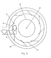
- the pressure-chamber grinder in accordance with the present invention comprises a grinder chamber 1 of substantially circular section, which is provided with a feed opening 3 for the material to be ground, fed as a gas-tight plug, and whose opposite end is provided with an outlet opening 5 for the material ground.
- Tangentially directed grinding-gas nozzles 7 are arranged as uniformly spaced around the entire circumference of the mantle face over at least a part of the mantle face 6 of the grinder chamber 1.
- the oblong grinder chamber 1 is, by means of a partition wall 8, divided into a pre-grinding chamber 9 and a grinding chamber 10 proper, which chambers are interconnected by means of at least two Laval nozzles 11 forming an angle with each other.
- the material-gas jets rushing through the nozzles at a supersonic speed intersect each other in the grinding chamber 10 placed immediately at the outlet side of the Laval nozzles 11, at which point a zone of collision of the material particles to be ground is formed.
- the coarse fraction coming from the classifier 17 connected to the outlet opening 5 of the grinding chamber 10 is returned to this zone.
- the collision zone is formed immediately in the proximity of the outlet side of the Laval nozzles 11 in order that the speed of the gas flows should not have time to be lowered.
- the location of the collision point and the extent of the collision zone can be affected by means of the angle between the Laval nozzles 11, which angle may vary within the limits of about 60 to 180°, whereat angles within the range of about 90 to 120 0 have proved most advantageous.
- the feed opening 3 may be located at any place near one end of the grinder chamber 1, preferably close to the mantle face 6, so that the material to be ground, fed into the grinder chamber by means of the plug feeder, is immediately subjected to the action of the grinding-gas flows coming from the nozzles 7.
- At least a'part of the mantle face 6 of the grinding chamber 10 provided with the outlet opening 5 is conical so that the cross-sectional area of the grinding chamber 10 becomes smaller towards the outlet opening 5, whereat the speed of the material-gas flow rushing out of the grinder becomes higher.
- each partition wall 8 in the direction of inlet of the flow,either conical or convex, whereat the feed openings of the Laval nozzles 11 placed in the partition wall 8 may be placed entirely at the face of the partition wall 8.
- the end of the grinder chamber 1 placed next to the feed opening 3 is provided with a pre-grinding portion 14, whose cross-sectional area is larger than that of the rest of the grinder chamber 1 and whose mantle face is provided with tangentially directed grinding-gas nozzles 7.
- the feed opening 3 of the grinder is placed at the proximity of the mantle face of the pre-grinding portion 14.
- the feed opening 3, to which the feeder pipe coming from the plug feeder and provided with a screw conveyor 4 is connected is located in the end wall 2. It is recommended that the material to be ground is, before it is fed into the pre-grinding portion 14, by means of a separate grinding-gas jet, accelerated to the same speed as the speed of the material-gas flow circulating in the pre-grinding portion 14.
- each partition wall 6, 12 is attached which is parallel to the circumference and which partition walls are concentric and have a height of at least half the overall height of the pre-grinding portion 14 so that they are slightly overlapping each other.
- the function of these partition walls 6, 12 is to operate as some sort of obstacle for the material flow fluidized in the pre-grinding portion 14, whereat the pregrinding and classification taking place in this portion are intensified.
- the classifier 17 in the pre-grinding chamber 9 so that its outlet end for the coarse fraction passes through the partitiion wall 8 at the centre point of this wall and extends to the zone of collision of the material-gas jets rushing through the Laval nozzles 11 so that the coarse fraction coming out of the classifier 17 is immediately subjected to a new grinding action.
- the classifier 17, which is preferably of the cyclone type, is via a connecting pipe 16 connected to the outlet opening 5 of the grinding chamber 10, from which the ground material-gas flow is passed into the classifier 17 tangentially.
- the coarse fraction is separated from the rest of the material flow by means of the centrifugal force and returned into the said collision or grinding zone.
- the fine fraction is passed through an outlet pipe 18 provided at the other end of the classifier 17 possibly into a subsequent pressure-chamber grinder, operating at a lower pressure, or straight into a product tank.
- the grinder chamber 1 may be positioned either vertically or horizontally, depending on the type of classifier 17 used and on the location of the classifier.
- the grinding gas is preferably used superheated water vapour at a pressure of at least 7 bars, the vapour being fed into the pre- grinding portion 14 through the nozzles 7 and a positive pressure of at least 3 bars being maintained in the pre-grinding portion 14 by means of the said vapour.
- the subsequent grinding chamber 10 into which the material-gas flow rushes at a supersonic speed through the Laval nozzles 11, appropriately a positive pressure of about 0.05 to 0.1 bar is maintained, the material-gas mixture being passed from the said chamber to the classifier 17.
Landscapes
- Engineering & Computer Science (AREA)
- Food Science & Technology (AREA)
- Disintegrating Or Milling (AREA)
- Electrical Discharge Machining, Electrochemical Machining, And Combined Machining (AREA)
- Combined Means For Separation Of Solids (AREA)
Priority Applications (1)
| Application Number | Priority Date | Filing Date | Title |
|---|---|---|---|
| AT82201499T ATE42478T1 (de) | 1981-11-27 | 1982-11-25 | Druckkammerzerkleinerer. |
Applications Claiming Priority (2)
| Application Number | Priority Date | Filing Date | Title |
|---|---|---|---|
| FI813812 | 1981-11-27 | ||
| FI813812A FI63869C (fi) | 1981-11-27 | 1981-11-27 | Tryckkammarkvarn |
Publications (3)
| Publication Number | Publication Date |
|---|---|
| EP0080773A2 true EP0080773A2 (fr) | 1983-06-08 |
| EP0080773A3 EP0080773A3 (en) | 1986-02-05 |
| EP0080773B1 EP0080773B1 (fr) | 1989-04-26 |
Family
ID=8514905
Family Applications (1)
| Application Number | Title | Priority Date | Filing Date |
|---|---|---|---|
| EP82201499A Expired EP0080773B1 (fr) | 1981-11-27 | 1982-11-25 | Broyeur à chambre pressurisé |
Country Status (8)
| Country | Link |
|---|---|
| US (1) | US4546926A (fr) |
| EP (1) | EP0080773B1 (fr) |
| AT (1) | ATE42478T1 (fr) |
| DE (1) | DE3279640D1 (fr) |
| DK (1) | DK153815C (fr) |
| FI (1) | FI63869C (fr) |
| SU (1) | SU1351512A3 (fr) |
| WO (1) | WO1983001915A1 (fr) |
Cited By (3)
| Publication number | Priority date | Publication date | Assignee | Title |
|---|---|---|---|---|
| WO1986002287A1 (fr) * | 1984-10-12 | 1986-04-24 | Oy Finnpulva Ab | Dispositif d'alimentation pour machine broyeuse a chambre de pression |
| AU582280B2 (en) * | 1985-09-18 | 1989-03-16 | Oy Finnpulva Ab | Grinder housing for a pressure chamber grinder |
| WO1998053908A3 (fr) * | 1997-05-28 | 1999-03-04 | Messer Griesheim Gmbh | Appareil et procede pour effectuer des reactions dans des couches de particules fluidisees |
Families Citing this family (12)
| Publication number | Priority date | Publication date | Assignee | Title |
|---|---|---|---|---|
| FI72897C (fi) * | 1983-03-04 | 1987-08-10 | Finnpulva Ab Oy | Inmatningsanordning foer en tryckkammarkvarnanlaeggning. |
| US5476093A (en) * | 1992-02-14 | 1995-12-19 | Huhtamaki Oy | Device for more effective pulverization of a powdered inhalation medicament |
| US5855326A (en) * | 1997-05-23 | 1999-01-05 | Super Fine Ltd. | Process and device for controlled cominution of materials in a whirl chamber |
| CA2212430A1 (fr) | 1997-08-07 | 1999-02-07 | George Volgyesi | Appareil inhalateur |
| US6038987A (en) * | 1999-01-11 | 2000-03-21 | Pittsburgh Mineral And Environmental Technology, Inc. | Method and apparatus for reducing the carbon content of combustion ash and related products |
| EP1282180A1 (fr) * | 2001-07-31 | 2003-02-05 | Xoliox SA | Procédé de fabrication de Li4Ti5O12 et matériau d'électrode |
| RU2209672C1 (ru) * | 2002-02-06 | 2003-08-10 | Государственное предприятие "Всероссийский научно-исследовательский институт физико-технических и радиотехнических измерений" | Вихревая мельница |
| US6789756B2 (en) | 2002-02-20 | 2004-09-14 | Super Fine Ltd. | Vortex mill for controlled milling of particulate solids |
| WO2003076338A1 (fr) * | 2002-03-08 | 2003-09-18 | Altair Nanomaterials Inc. | Procede de fabrication de nano-oxydes et d'oxydes submicroniques de lithium-metaux de transition |
| KR20080063511A (ko) * | 2005-10-21 | 2008-07-04 | 알타이어나노 인코포레이티드 | 리튬 이온 배터리들 |
| KR20090129500A (ko) * | 2007-03-30 | 2009-12-16 | 알타이어나노 인코포레이티드 | 리튬 이온 전지의 제조방법 |
| CN119909824B (zh) * | 2025-04-03 | 2025-07-15 | 绵阳流能粉体设备有限公司 | 一种磷酸铁锂制备方法及混合粉碎设备 |
Family Cites Families (12)
| Publication number | Priority date | Publication date | Assignee | Title |
|---|---|---|---|---|
| US2672296A (en) * | 1949-01-04 | 1954-03-16 | Blaw Knox Co | Fluid impact pulverizer |
| US2612320A (en) * | 1949-01-05 | 1952-09-30 | Blaw Knox Co | Impact pulverizer |
| US2846151A (en) * | 1953-08-17 | 1958-08-05 | Bayer Ag | Selective disintegration and separation of pigments |
| US3186648A (en) * | 1963-05-27 | 1965-06-01 | Grace W R & Co | Fluid energy mill |
| US3312342A (en) * | 1964-03-27 | 1967-04-04 | Du Pont | Process and apparatus for impacting and elutriating solid particles |
| DE1298393B (de) * | 1965-09-21 | 1969-06-26 | Fluid Energy Proc And Equipmen | Strahlmuehle zum Zerkleinern und Dispergieren von Feststoffen in einer Traegerfluessigkeit |
| US3643875A (en) * | 1969-06-27 | 1972-02-22 | Texaco Inc | Fluid energy grinding method and system |
| US3675858A (en) * | 1970-06-18 | 1972-07-11 | Hewlett Packard Co | Angular impact fluid energy mill |
| GB1329941A (en) * | 1972-01-05 | 1973-09-12 | Texaco Development Corp | Fluid energy grinding method and system |
| GB1422105A (en) * | 1974-05-17 | 1976-01-21 | Fluid Energy Process Equip | Process and apparatus for mixing pulverizing and grinding black powder |
| US4056233A (en) * | 1976-10-01 | 1977-11-01 | Fay Edwin F | Apparatus for pulverizing solid materials |
| US4304360A (en) * | 1979-12-31 | 1981-12-08 | International Business Machines Corporation | Xerograhic toner manufacture |
-
1981
- 1981-11-27 FI FI813812A patent/FI63869C/fi not_active IP Right Cessation
-
1982
- 1982-11-17 WO PCT/FI1982/000057 patent/WO1983001915A1/fr not_active Ceased
- 1982-11-17 US US06/518,800 patent/US4546926A/en not_active Expired - Fee Related
- 1982-11-25 EP EP82201499A patent/EP0080773B1/fr not_active Expired
- 1982-11-25 DE DE8282201499T patent/DE3279640D1/de not_active Expired
- 1982-11-25 AT AT82201499T patent/ATE42478T1/de active
-
1983
- 1983-07-07 SU SU833614027A patent/SU1351512A3/ru active
- 1983-07-13 DK DK323383A patent/DK153815C/da not_active IP Right Cessation
Cited By (3)
| Publication number | Priority date | Publication date | Assignee | Title |
|---|---|---|---|---|
| WO1986002287A1 (fr) * | 1984-10-12 | 1986-04-24 | Oy Finnpulva Ab | Dispositif d'alimentation pour machine broyeuse a chambre de pression |
| AU582280B2 (en) * | 1985-09-18 | 1989-03-16 | Oy Finnpulva Ab | Grinder housing for a pressure chamber grinder |
| WO1998053908A3 (fr) * | 1997-05-28 | 1999-03-04 | Messer Griesheim Gmbh | Appareil et procede pour effectuer des reactions dans des couches de particules fluidisees |
Also Published As
| Publication number | Publication date |
|---|---|
| ATE42478T1 (de) | 1989-05-15 |
| DK153815B (da) | 1988-09-12 |
| WO1983001915A1 (fr) | 1983-06-09 |
| EP0080773A3 (en) | 1986-02-05 |
| DE3279640D1 (en) | 1989-06-01 |
| SU1351512A3 (ru) | 1987-11-07 |
| US4546926A (en) | 1985-10-15 |
| FI63869B (fi) | 1983-05-31 |
| FI63869C (fi) | 1983-09-12 |
| DK323383A (da) | 1983-07-13 |
| DK323383D0 (da) | 1983-07-13 |
| DK153815C (da) | 1989-02-20 |
| EP0080773B1 (fr) | 1989-04-26 |
Similar Documents
| Publication | Publication Date | Title |
|---|---|---|
| EP0080773A2 (fr) | Broyeur à chambre pressurisé | |
| CA1213573A (fr) | Broyeur | |
| US4451005A (en) | Gas flow type crushing and classifying apparatus | |
| GB1584390A (en) | Apparatus for pulverising solid materials | |
| US2690880A (en) | Rectilinear pulverizer | |
| US4768721A (en) | Grinder housing for a pressure chamber grinder | |
| US3837583A (en) | Multi-stage jet mill | |
| US3648936A (en) | Constant acceleration fluid energy mill | |
| US4735708A (en) | Cyclone separator means | |
| EP0218671B1 (fr) | Broyeur a jet d'air pour broyage fin et/ou cryogenique et traitement de surface de materiaux de preference durs, elastiques et/ou thermoplastiques | |
| US4811907A (en) | Method and apparatus for improving the grinding result of a pressure chamber grinder | |
| CA1198401A (fr) | Broyeur a chambre sous pression | |
| US3508714A (en) | Multiple section fluid energy grinding mill | |
| US3550868A (en) | Fluid energy milling solid granular material | |
| EP0303608B1 (fr) | Procede et appareil permettant d'ameliorer le produit de broyage d'un broyeur a chambre de pression | |
| EP0211117A2 (fr) | Procédé et appareil pour la production de poudre finement divisée | |
| US3584797A (en) | Multiple section fluid energy grinding mill | |
| CA1255911A (fr) | Chambre de broyage pour broyeur sous pression | |
| RU2072900C1 (ru) | Способ вихревого измельчения волокнистых материалов и устройство для его осуществления | |
| SU1258484A1 (ru) | Гидравлический классификатор | |
| RU21876U1 (ru) | Установка и струйно-роторная помольная камера для измельчения | |
| US3456887A (en) | Apparatus for treating solid granular material | |
| JPS6242753A (ja) | 微細粉末製造方法及び装置 | |
| NO156358B (no) | Trykkammerkvern. | |
| SU1072894A2 (ru) | Роторна мельница |
Legal Events
| Date | Code | Title | Description |
|---|---|---|---|
| PUAI | Public reference made under article 153(3) epc to a published international application that has entered the european phase |
Free format text: ORIGINAL CODE: 0009012 |
|
| AK | Designated contracting states |
Designated state(s): AT BE CH DE FR GB IT LI SE |
|
| PUAL | Search report despatched |
Free format text: ORIGINAL CODE: 0009013 |
|
| AK | Designated contracting states |
Designated state(s): AT BE CH DE FR GB IT LI SE |
|
| 17P | Request for examination filed |
Effective date: 19860729 |
|
| 17Q | First examination report despatched |
Effective date: 19871215 |
|
| GRAA | (expected) grant |
Free format text: ORIGINAL CODE: 0009210 |
|
| AK | Designated contracting states |
Kind code of ref document: B1 Designated state(s): AT BE CH DE FR GB IT LI SE |
|
| REF | Corresponds to: |
Ref document number: 42478 Country of ref document: AT Date of ref document: 19890515 Kind code of ref document: T |
|
| REF | Corresponds to: |
Ref document number: 3279640 Country of ref document: DE Date of ref document: 19890601 |
|
| ITF | It: translation for a ep patent filed | ||
| ET | Fr: translation filed | ||
| PGFP | Annual fee paid to national office [announced via postgrant information from national office to epo] |
Ref country code: SE Payment date: 19891017 Year of fee payment: 8 |
|
| PGFP | Annual fee paid to national office [announced via postgrant information from national office to epo] |
Ref country code: FR Payment date: 19891027 Year of fee payment: 8 |
|
| PGFP | Annual fee paid to national office [announced via postgrant information from national office to epo] |
Ref country code: GB Payment date: 19891031 Year of fee payment: 8 Ref country code: BE Payment date: 19891031 Year of fee payment: 8 |
|
| PGFP | Annual fee paid to national office [announced via postgrant information from national office to epo] |
Ref country code: CH Payment date: 19891110 Year of fee payment: 8 |
|
| PGFP | Annual fee paid to national office [announced via postgrant information from national office to epo] |
Ref country code: DE Payment date: 19891116 Year of fee payment: 8 |
|
| ITTA | It: last paid annual fee | ||
| PGFP | Annual fee paid to national office [announced via postgrant information from national office to epo] |
Ref country code: AT Payment date: 19891130 Year of fee payment: 8 |
|
| PLBE | No opposition filed within time limit |
Free format text: ORIGINAL CODE: 0009261 |
|
| STAA | Information on the status of an ep patent application or granted ep patent |
Free format text: STATUS: NO OPPOSITION FILED WITHIN TIME LIMIT |
|
| 26N | No opposition filed | ||
| PG25 | Lapsed in a contracting state [announced via postgrant information from national office to epo] |
Ref country code: GB Effective date: 19901125 Ref country code: AT Effective date: 19901125 |
|
| PG25 | Lapsed in a contracting state [announced via postgrant information from national office to epo] |
Ref country code: SE Effective date: 19901126 |
|
| PG25 | Lapsed in a contracting state [announced via postgrant information from national office to epo] |
Ref country code: LI Effective date: 19901130 Ref country code: CH Effective date: 19901130 Ref country code: BE Effective date: 19901130 |
|
| BERE | Be: lapsed |
Owner name: NIEMI JOUKO Effective date: 19901130 |
|
| GBPC | Gb: european patent ceased through non-payment of renewal fee | ||
| PG25 | Lapsed in a contracting state [announced via postgrant information from national office to epo] |
Ref country code: FR Effective date: 19910731 |
|
| REG | Reference to a national code |
Ref country code: CH Ref legal event code: PL |
|
| PG25 | Lapsed in a contracting state [announced via postgrant information from national office to epo] |
Ref country code: DE Effective date: 19910801 |
|
| REG | Reference to a national code |
Ref country code: FR Ref legal event code: ST |
|
| EUG | Se: european patent has lapsed |
Ref document number: 82201499.9 Effective date: 19910705 |