EP0080774A2 - Tête de remplissage à contre-pression actionnée par le récipient - Google Patents
Tête de remplissage à contre-pression actionnée par le récipient Download PDFInfo
- Publication number
- EP0080774A2 EP0080774A2 EP82201500A EP82201500A EP0080774A2 EP 0080774 A2 EP0080774 A2 EP 0080774A2 EP 82201500 A EP82201500 A EP 82201500A EP 82201500 A EP82201500 A EP 82201500A EP 0080774 A2 EP0080774 A2 EP 0080774A2
- Authority
- EP
- European Patent Office
- Prior art keywords
- valve
- container
- counterpressure
- filling
- containers
- Prior art date
- Legal status (The legal status is an assumption and is not a legal conclusion. Google has not performed a legal analysis and makes no representation as to the accuracy of the status listed.)
- Granted
Links
Images
Classifications
-
- B—PERFORMING OPERATIONS; TRANSPORTING
- B67—OPENING, CLOSING OR CLEANING BOTTLES, JARS OR SIMILAR CONTAINERS; LIQUID HANDLING
- B67C—CLEANING, FILLING WITH LIQUIDS OR SEMILIQUIDS, OR EMPTYING, OF BOTTLES, JARS, CANS, CASKS, BARRELS, OR SIMILAR CONTAINERS, NOT OTHERWISE PROVIDED FOR; FUNNELS
- B67C3/00—Bottling liquids or semiliquids; Filling jars or cans with liquids or semiliquids using bottling or like apparatus; Filling casks or barrels with liquids or semiliquids
- B67C3/02—Bottling liquids or semiliquids; Filling jars or cans with liquids or semiliquids using bottling or like apparatus
- B67C3/06—Bottling liquids or semiliquids; Filling jars or cans with liquids or semiliquids using bottling or like apparatus using counterpressure, i.e. filling while the container is under pressure
- B67C3/08—Bottling liquids or semiliquids; Filling jars or cans with liquids or semiliquids using bottling or like apparatus using counterpressure, i.e. filling while the container is under pressure and subsequently lowering the counterpressure
-
- B—PERFORMING OPERATIONS; TRANSPORTING
- B67—OPENING, CLOSING OR CLEANING BOTTLES, JARS OR SIMILAR CONTAINERS; LIQUID HANDLING
- B67C—CLEANING, FILLING WITH LIQUIDS OR SEMILIQUIDS, OR EMPTYING, OF BOTTLES, JARS, CANS, CASKS, BARRELS, OR SIMILAR CONTAINERS, NOT OTHERWISE PROVIDED FOR; FUNNELS
- B67C3/00—Bottling liquids or semiliquids; Filling jars or cans with liquids or semiliquids using bottling or like apparatus; Filling casks or barrels with liquids or semiliquids
- B67C3/02—Bottling liquids or semiliquids; Filling jars or cans with liquids or semiliquids using bottling or like apparatus
- B67C3/22—Details
- B67C3/24—Devices for supporting or handling bottles
- B67C3/244—Bottle lifting devices actuated by jacks, e.g. hydraulic, pneumatic
-
- B—PERFORMING OPERATIONS; TRANSPORTING
- B67—OPENING, CLOSING OR CLEANING BOTTLES, JARS OR SIMILAR CONTAINERS; LIQUID HANDLING
- B67C—CLEANING, FILLING WITH LIQUIDS OR SEMILIQUIDS, OR EMPTYING, OF BOTTLES, JARS, CANS, CASKS, BARRELS, OR SIMILAR CONTAINERS, NOT OTHERWISE PROVIDED FOR; FUNNELS
- B67C3/00—Bottling liquids or semiliquids; Filling jars or cans with liquids or semiliquids using bottling or like apparatus; Filling casks or barrels with liquids or semiliquids
- B67C3/02—Bottling liquids or semiliquids; Filling jars or cans with liquids or semiliquids using bottling or like apparatus
- B67C3/22—Details
- B67C3/26—Filling-heads; Means for engaging filling-heads with bottle necks
- B67C3/2614—Filling-heads; Means for engaging filling-heads with bottle necks specially adapted for counter-pressure filling
- B67C3/2625—Filling-heads; Means for engaging filling-heads with bottle necks specially adapted for counter-pressure filling the liquid valve being opened automatically when a given counter-pressure is obtained in the container to be filled
- B67C3/2628—Filling-heads; Means for engaging filling-heads with bottle necks specially adapted for counter-pressure filling the liquid valve being opened automatically when a given counter-pressure is obtained in the container to be filled and the filling operation stopping when the liquid rises to a level at which it closes a vent opening
-
- B—PERFORMING OPERATIONS; TRANSPORTING
- B67—OPENING, CLOSING OR CLEANING BOTTLES, JARS OR SIMILAR CONTAINERS; LIQUID HANDLING
- B67C—CLEANING, FILLING WITH LIQUIDS OR SEMILIQUIDS, OR EMPTYING, OF BOTTLES, JARS, CANS, CASKS, BARRELS, OR SIMILAR CONTAINERS, NOT OTHERWISE PROVIDED FOR; FUNNELS
- B67C7/00—Concurrent cleaning, filling, and closing of bottles; Processes or devices for at least two of these operations
- B67C7/0006—Conveying; Synchronising
- B67C7/002—General lay-out of bottle-handling machines
-
- B—PERFORMING OPERATIONS; TRANSPORTING
- B67—OPENING, CLOSING OR CLEANING BOTTLES, JARS OR SIMILAR CONTAINERS; LIQUID HANDLING
- B67C—CLEANING, FILLING WITH LIQUIDS OR SEMILIQUIDS, OR EMPTYING, OF BOTTLES, JARS, CANS, CASKS, BARRELS, OR SIMILAR CONTAINERS, NOT OTHERWISE PROVIDED FOR; FUNNELS
- B67C3/00—Bottling liquids or semiliquids; Filling jars or cans with liquids or semiliquids using bottling or like apparatus; Filling casks or barrels with liquids or semiliquids
- B67C3/02—Bottling liquids or semiliquids; Filling jars or cans with liquids or semiliquids using bottling or like apparatus
- B67C3/22—Details
- B67C3/26—Filling-heads; Means for engaging filling-heads with bottle necks
- B67C2003/2651—The liquid valve being carried by the vent tube
-
- B—PERFORMING OPERATIONS; TRANSPORTING
- B67—OPENING, CLOSING OR CLEANING BOTTLES, JARS OR SIMILAR CONTAINERS; LIQUID HANDLING
- B67C—CLEANING, FILLING WITH LIQUIDS OR SEMILIQUIDS, OR EMPTYING, OF BOTTLES, JARS, CANS, CASKS, BARRELS, OR SIMILAR CONTAINERS, NOT OTHERWISE PROVIDED FOR; FUNNELS
- B67C3/00—Bottling liquids or semiliquids; Filling jars or cans with liquids or semiliquids using bottling or like apparatus; Filling casks or barrels with liquids or semiliquids
- B67C3/02—Bottling liquids or semiliquids; Filling jars or cans with liquids or semiliquids using bottling or like apparatus
- B67C3/22—Details
- B67C3/26—Filling-heads; Means for engaging filling-heads with bottle necks
- B67C2003/2657—Filling-heads; Means for engaging filling-heads with bottle necks specially adapted for filling cans
Definitions
- This invention relates to the field of filling containers such as bottles and cans with carbonated liquids such as soft drinks. More particularly, the invention relates to an improved machine and method for filling such containers, and,still more particularly, to an improved filling valve for use in such machinery.
- a filling valve for use in a carbonated liquid bottling machine is shown in U.S. patent 4,089,353 to Antonelli.
- a filling valve is shown which connects a bottle to be filled with a tank containing a supply of liquid with which the bottle is to be filled, and of the pressurized gas for counterpressurizing.
- the valve is controlled by cam means communicating with the outside of the tank for actuation such that the gas is first admitted to the bottle.
- the bottle is filled with the counterpressurizing gas until the pressures of the gas and the liquid is equal.
- a second valve is then opened allowing the liquid to flow into the bottle under the influence of gravity.
- the cam actuator closes the valve and the bottle is lowered away from the valve in a sequenced operation.
- the pressure in the neck of the bottle is then controllably released by a so-called "snift" valve and the bottle quickly capped or crowned.
- the filling valve of the Antonelli reference is useful and has been a success, nevertheless it would be desirable to further improve it.
- the Antonelli valve in a presently popular embodiment stands sufficiently tall within the tank containing the counterpressurizing gas and the product with which the bottle is to be filled must be more than six inches deep. Accordingly, if filling machinery using these valves is sold in this country the tank is classified as a pressure vessel and must be very heavily constructed in order to meet applicable code specifications.
- the Antonelli valve also requires an actuator external to the tank for controlling the flow of gas and thereafter of product into the bottle to be filled. See also U.S. patent 3,090,408 to Naecker.
- the Antonelli reference requires a cam to actuate the snift valve to release the pressure within the neck of the bottle after filling.
- the Antonelli patent places the gas and the product within the same chamber. Therefore, in order to clean the valve it must be removed from the machine as there is no way to reliably flow a detergent and water solution through all parts of the valve.
- the Antonelli valve rotates with the bottle and product tank and is controlled by a stationary actuator, so that it is operated in accordance with its position with respect to the actuator and opens, releasing product, regardless of whether or not there is a bottle in place under the valve when it is opened. Accordingly, if a bottle should break or for some reason not be present under the valve, product is lost.
- a further object of the invention is to provide a valve filling machine which is capable of higher speed operation than possible in the prior art.
- a further object of the invention is to provide a bottle filling machine in which there are provided no external cam actuators which require some overlap of cycle timing sequences thus necessitating slower operation.
- An ultimate object of the invention is to provide improved filling machine performance at reduced cost.
- the present invention satisfies the above-mentioned needs of the art and objects of the invention, as well as others which will be apparent to those skilled in the art, by its provision of a filling valve which is entirely actuated by the raising of a container, for example a bottle, to engage a lower surface of the valve.
- a first valve is opened admitting counterpressure gas into the bottle.
- a second valve automatically opens - i.e., without cam actuators, further movement of the bottle, or the like - allowing product to flow into the bottle.
- product filling stops Upon the level of the product in the bottle reaching a vent hole.
- the bottle is lowered away from the filling valve.
- the product valve closes first; as the bottle drops further away from the valve, product trapped in the neck of the bottle is permitted to fill the bottle to its desired level.
- a snift port is uncovered merely by the action of the valve allowing any pressure remaining in the neck of the bottle to be released to the atmosphere, without the necessity of a cam actuated, carefully sequenced snift valve.
- the bottle can thereafter be capped or crowned as the case may be by conventional ; methods.
- the improved filling valve of the invention has applicability to the filling of both bottles and cans.
- the volume of the air space above the product in the can is sufficiently increased before the product in the can is exposed to atmosphere that no snift valve is even required.
- the present invention relates to filling of containers with carbonated liquids.
- the invention is applicable to both filling of cans and bottles.
- there are detail differences in the machinery used to fill cans and bottles due obviously to their differing configurations, and also to the distance between the liquid level and the top of the can or bottle.
- the following description is applicable to the filling of both cans and bottles; where significant differences appear, they are explained.
- Those skilled in the art will recognize that there are other non-essential distinctions not specifically mentioned as well.
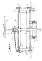
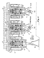
- Fig. 1 shows a cross-sectional view of a machine for filling containers with carbonated liquids.
- the machine comprises a circular array of filling valves 10 mounted to a frame journaled for rotation upon bearings 12 with respect to a stationary frame 14.
- the product with which the containers are to be filled is supplied through a central tube 16 and passes outwardly to the filling valves by means of one or more tubes 18 which are connected to a rotating circular manifold 20 interconnecting all of the filling valves 10.
- the level of the product (not shown) within tubes 18 and manifold 20 is controlled by conventional float valves 22.
- a baffle 23 prevents surging in the float chamber.
- the counterpressure gas typically carbon dioxide at 40 psi, for example, is supplied to the filling valves 10 through tubes 24.
- the C0 2 gas is supplied to a central chamber 26 through a tube 28 controlled by a valve 30 connected to a C0 2 inlet tube 32.
- a plurality of air operated pneumatic cylinders 34 which serve to raise and lower the bottles into engagement with the filling valve 10. These also rotate with the manifold 20 and filling valves 10.
- the air cylinders may in a preferred embodiment all be connected to an air manifold at substantially constant pressure.
- the actual motion of the containers into engagement with the filling valves 10 is controlled by, e.g., a stationary circular cam 36 against which ride cam rollers 38 operatively connected to the pistons of the pneumatic cylinders 34, such that the relative radial position of the cylinders 34 with respect to the stationary cam 36 controls the height of the bottle with respect to the filling valves 10.
- a container filling machine be adaptable to operate with a wide variety of differing containers which vary not only as to volume but also as to height.
- such compensation is provided by adjustment of elevating spacer pieces 40 which are changed to compensate for the heights of various bottles.
- the product supply tube 16 telescopes about a telescopic joint 42 in order to enable relative adjustment of the upper portion of the filling machine with respect to the lower.
- small variations are accomplished without adjustment insofar as the control of the amount of product inserted into containers is controlled automatically as will be detailed in further detail below. If gross variations in container volume are encountered, such as with 48 oz. soft drink bottles, their filling can be controlled in the same manner, although some slowing of the overall speed of operation of the container filling machine may be necessary to provide enough time for such large bottles to be filled.
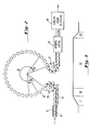
- Fig. 2 shows a schematic plan view of the filling machine of the invention.
- Containers 50 to be filled are supplied along a conveyor 52, e.g., at the left of the machine.
- a conventional worm infeed screw 54 operates in conjunction with conventional starwheels 56 to properly index the containers 50 to be filled onto platforms supported by the individual air cylinders 34 of Fig. 1.
- the containers 50 to be filled then travel around a circular path underneath the individual filling valves and are filled.
- Fig. 2 shows the division of the total circular path into five segments labeled I, II, III and IV and a fifth unlabeled area. The four numbered areas refer to various stages in the cycle of container filling.
- area I represents the portion of the total rotation during which engagement of the bottle with the filling valve takes place; area II represents counterpressurization; area III represents filling; and area IV represents lowering of the bottle with respect to the filling valve, during which the snift operation takes place, in the case of bottles.
- each filling valve comprised an actuator which as the filling machine rotated was moved by contact with a fixed actuator. So that such operations could each be fully completed in their proper sequence before the next begins, it was always necessary to allow more time than should theoretically have been required for the operation to be performed, in order to allow for mechanical variations and the like.
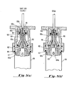
- Figs. 4A through 4C show the bottle valve operating stages in the bottle filling cycle according to the method of the invention.
- Fig. 4A shows the valve prior to the bottle being raised, i.e., in the inactive portion I of the cycle shown in Figs. 2 and 3. The valve takes the same position during the snift portion IV.
- Fig. 4B shows stage II, the counterpressurization stage and Fig. 4C shows stage III, during which filling takes place.
- the valve indicated generally at 10, comprises a fixed valve body member 60 which may be affixed directly to the plate 62 forming the bottom of the tank in which the product, i.e., the liquid with which the bottle is to be filled, is contained.
- the valve body 60 is held to the plate by cap screws 64 concentric with first compression springs 66; one end of each spring abuts the fixed portion 60 of the valve while the other abuts a slidable first actuator portion 68, sliding on cap screws 64; antifriction bushings may be interposed therebetween.
- Valve actuator member 68 contains a sealing rubber 70 sized to coact with the mouth of a bottle 72 when the bottle is raised with respect to the valve 10 by the cam 36 of Fig. 1.
- the valve body 60 also comprises a central portion 60a which may be formed integrally with the outer portion of the valve body 60 and separated therefrom by an annulus of product passage holes 60b drilled in a ring pattern around the upper surface of the valve 60.
- the valve body 60 together with central portion 60a may be made up of several assembled pieces, as is also true of other of the valve parts, for reasons of manufacturing and assembly convenience; the view shown is selected for clarity.
- a recess 60e is formed in the inner portion 60a of the fixed valve body member 60, within which slides a movable product valve member 74, which carries a circular product sealing gasket member 75 adapted to more with a sealing surface 60e on the only 60 of the valve 10.
- the valve member 74 When, as described beiow, the valve member 74 is l'Lted vertically, the gasket surface 75 leaves the mating surface 60c permitting product to flow through the annular ring of holes 60B and down into the bottle 72.
- the product also passes in its path into the bottle 72 through a plurality of holes 76a formed in an annular ring about a movable counterpressure valve member 76 which also comprises a vent tube 76b extending into the bottle.
- the upper end of the counterpressure valve member 76b also comprises an annular array of holes 76c through which gas can flow when counterpressure sealing member 76d is moved away from the first movable product valve member 74, permitting counterpressure gas to flow annularly down through an orifice 60f formed in the center of the valve body 60, through the first plurality of holes 76c in the vent tube, down the center of the vent tube 76b and out into the bottle.
- Fig. 4A is common to stages I, the inactive stage, during which the bottle is being raised, and stage IV, the snift stage. It will accordingly be described before and after the bottle has been filled.
- the valve of the invention 10 is shown confining product at a sealing surface 60c of a fixed valve body member 60 which mates with a gasket member 75 carried by a movable product valve portion 74.
- the counterpressurizing gas supplied through a tube 80 and an orifice 60f formed in the valve body 60 is confined by a sealing means 76d carried by a second movable valve member 76, which also comprises the vent tube 76b which extends into the bottle.
- a sealing means 76d carried by a second movable valve member 76, which also comprises the vent tube 76b which extends into the bottle.
- Fig. 4B the bottle 72 is shown having sealingly engaged the sealing rubber 70 and having pushed the movable valve portion 68 upwardly compressing spring 66.
- the movable portion 68 comprises a surface 68a which engages the counterpressure valve member 76 which causes it and therefore counterpressure sealing means 76d to move upwardly, permitting gas to flow through the orifice 60f, through the orifices 76c and down into the bottle 72 through the vent tube portion 76b thus counterpressurizing the bottle.
- valve member 74 when the force exerted by the counterpressure in the bottle 72 on the undersurfaces 74c of the valve member 74, is substantially equal to that exerted by the product on the upper surface 74b of the valve member 74 - i.e., when counterpressurization is completed - spring 84 is permitted to raise the valve member 74, permitting product to flow past sealing gasket 75 and engaging surface 60c, through orifices 76a, and into the bottle, as shown in Fig. 4C. At the same time counterpressurizing gas flows out of the bottle 72 and up the vent tube 76b.
- the balance of pressure between the counterpressure in the bottle and the fluid pressure controls when the product valve 74 opens, and is a function of the relative areas of the top of the valve 74b and its bottom 74c, the relative pressures of gas and product, and the pressure exerted by spring 84 after having been compressed upon the opening of the counterpressure valve 76.
- terms such as “substantial equality of pressure”, i.e., referring to counterpressure gas and the product on the product valve 74 are to be interpreted to include all these factors.
- valve members 74 and 76 drop together under the influence of springs 84 and 86. Compressed gas in the "trap" area between the annular gasket member 75 and the mating surface 60c prevent any more product from falling through the annular holes 76A while the springs84 and 86 are closing both valves 74 and 76 simultaneously.
- the product remaining in the annular area around the vent tube portion 76e after filling stops flows into the bottle 72 when the bottle 72 and the movable valve portion 68 are being lowered away from the stationary portion 60, thus compensating for the volume of the bottle lost to the vent tube 76b during the filling operation while not wasting product.
- the movable valve member 68 follows along with the bottle until it reaches the rest position shown in Fig. 4A at which time the seal between the mouth of the bottle 72 and the gasket * surface 70 is broken.
- the volume of the sealed region comprising the head space of the bottle and the interior of the valve up to gasket 75 increases with the dropping of the member 68 together with the bottle 72, being sealed by sealing rubber 70, so that less snift is required than in prior art such as the Antonelli patent referred to above where there was no equivalent increase of the sealed head space volume after filling.
- the snift operation can be carried out simply by exposure of a snift port 90 (Fig. 4A) to atmospheric pressure, uncovered as valve member 68 moves, rather than requiring a carefully designed valve and sequenced actuator as in the prior art.
- Figs. 5A and 5B show corresponding views of the counterpressure filling valve of the invention in an embodiment suitable for filling conventional cans.
- Fig. 5A shows the valve closed position which as in the case of the bottle filling valve of Figs. 4A through 4C is common to the valve closed position as well as the snift position while Fig. 5B shows the valve in the product filling position.
- the intermediate position, during which the can is counterpressurized, is not shown for purposes of simplicity, but will be explained in general terms.
- the can filling valve as does the bottle filling valve, comprises a stationary portion 100, a first movable valve body member 102, a counterpressure filling valve 104, which may be formed integrally with the first valve member 102, as shown, and a product filling valve 106.
- the stationary portion 100 contains central portion 100b defined by an annular ring of orifices 100a and has a recess 100c formed therein in which slides the product valve 106 which in turn carries the counterpressure valve 104.
- the fixed member 100 can be made in several portions as desired.
- a can 108 is shown in close conjunction to the movable portion 102 which is controlled by an internal spring 110.
- the movable portion 102 is desirably made of a plastic material and is the only part which needs to be substituted in order to allow changing of can neck sizes.
- the movable portion 102 is formed with rounded or chamfered area 102a which serves as a can guide so as to properly center the can 108 on the movable portion 102.
- the 0-ring 112 contacts a portion of the can of invariant diameter, so that relative movement therebetween is possible while the seal is maintained.
- the product flows down around the product valve 106 and through orifices 102b formed in the movable portion 102 permitting the can to be filled.
- the counterpressure gas leaves the can 108 through a central orifice 104b in the counterpressure valve 104, until the level of the product reaches sufficiently high to close a ball check valve 120 carried by the movable portion 102.
- this ball valve closes counterpressure gas can no longer be expelled from the can 108 and filling stops.
- the cam supporting the can allows it to drop away at which time the counterpressure and product valves, 104 and 106 respectively, close simultaneously.
- the can 108 continues to drop away but remains in sealing engagement with 0-ring 112 at its mouth while it moves an appreciable distance, during which time the volume of gas in the head space of the can is increased without exposure to the atmosphere such that no snift port or valve is required.
- the can is thereafter capped typically by a double sealing method as well understood in the prior art and passed to subsequent packaging and distribution stages.
- valve of the invention fulfills the needs of the art and objects of the invention listed above. Specifically, provision of a valve operated solely by the containers' pressing against a spring opened valve together with internal springs for complete control of the sequence of counterpressure and filling operations without interposition of externally operated cams or sequentially stepwise raised containers both simplifies the valve construction, rendering it less expensive and more foolproof of operation, and shortens the overall assembly to the point that the liquid tank need no longer be a pressure vessel. Furthermore, segregation of the liquid and counterpressure gas supply (as opposed to having both in a single tank) allows easy cleaning of the valve in place.
- valve of the invention permits the bottle or can to move an appreciable distance after being sealed to the movable portion of the valve. This provides a better seal than valves in which the bottle or can simply is contacted against a seal member, and also renders the container height adjustment less critical, while allowing the volume of gas within the head space of the container after filling to expand before breaking the container/valve seal, thus rendering the snift operation much simpler and requiring less apparatus.
- the fact that the valve of the invention only opens when a container is present and correctly aligned provides an automatic fail- preventing; loss of present without or can presence sensors or the like.
Landscapes
- Filling Of Jars Or Cans And Processes For Cleaning And Sealing Jars (AREA)
Applications Claiming Priority (2)
| Application Number | Priority Date | Filing Date | Title |
|---|---|---|---|
| US325289 | 1981-11-27 | ||
| US06/325,289 US4442873A (en) | 1981-11-27 | 1981-11-27 | Container actuated counterpressure filling valve |
Publications (3)
| Publication Number | Publication Date |
|---|---|
| EP0080774A2 true EP0080774A2 (fr) | 1983-06-08 |
| EP0080774A3 EP0080774A3 (en) | 1984-03-28 |
| EP0080774B1 EP0080774B1 (fr) | 1988-07-27 |
Family
ID=23267251
Family Applications (1)
| Application Number | Title | Priority Date | Filing Date |
|---|---|---|---|
| EP82201500A Expired EP0080774B1 (fr) | 1981-11-27 | 1982-11-25 | Tête de remplissage à contre-pression actionnée par le récipient |
Country Status (6)
| Country | Link |
|---|---|
| US (1) | US4442873A (fr) |
| EP (1) | EP0080774B1 (fr) |
| AU (1) | AU557696B2 (fr) |
| BR (1) | BR8207010A (fr) |
| CA (1) | CA1194845A (fr) |
| DE (1) | DE3278812D1 (fr) |
Cited By (12)
| Publication number | Priority date | Publication date | Assignee | Title |
|---|---|---|---|---|
| EP0154050A1 (fr) * | 1984-01-26 | 1985-09-11 | Crown Cork & Seal Company, Inc. | Têtes de remplissage de boîtes métalliques en contre-pression |
| DE3603172A1 (de) * | 1986-02-03 | 1987-08-06 | Seitz Enzinger Noll Masch | Fuellelement fuer gegendruckfuellmaschinen |
| GB2189473A (en) * | 1986-04-21 | 1987-10-28 | Figgie Int Inc | Filling valves for cans and like containers |
| US4750533A (en) * | 1981-11-27 | 1988-06-14 | Crown Cork & Seal Company, Inc. | Filling valve for counterpressure filling of cans |
| US4986318A (en) * | 1981-11-27 | 1991-01-22 | Crown Cork & Seal Company, Inc. | Filling valve for counterpressure filling of cans |
| US5145008A (en) * | 1985-04-05 | 1992-09-08 | Crown Cork & Seal Company, Inc. | Filling valve for counterpressure filling of cans |
| US5150740A (en) * | 1989-10-12 | 1992-09-29 | Crown Cork & Seal Company, Inc. | Filling valve |
| EP0516604A1 (fr) * | 1991-05-28 | 1992-12-02 | Crown Cork Company (Belgium) N.V. | Perfectionnement aux dispositifs de remplissage de bouteilles |
| WO1994010079A1 (fr) * | 1992-10-30 | 1994-05-11 | Simonazzi S.P.A. | Procede pour remplir des recipients avec des liquides, en particulier des canettes, et systeme de valve de remplissage pour mettre en oeuvre le procede |
| ITFI20100044A1 (it) * | 2010-03-23 | 2011-09-24 | Mec Ciani Alberto & C Snc Off | "macchina per imbottigliare liquidi alimentari" |
| EP3498658A1 (fr) * | 2017-11-30 | 2019-06-19 | Sidel Participations | Machine de remplissage de récipients avec un produit coulant sous pression |
| WO2025096535A1 (fr) * | 2023-10-31 | 2025-05-08 | Bubbled Box, Llc | Emballage périssable carbonaté multi-matériaux |
Families Citing this family (28)
| Publication number | Priority date | Publication date | Assignee | Title |
|---|---|---|---|---|
| DE3909404A1 (de) * | 1988-05-10 | 1989-11-16 | Seitz Enzinger Noll Masch | Verfahren zum abfuellen von fluessigem fuellgut in flaschen, dosen oder dergleichen gefaesse sowie fuellelement zur verwendung bei diesem verfahren |
| US5085255A (en) * | 1988-06-16 | 1992-02-04 | Lawarre Precision Technologies Inc. | Filling valve apparatus |
| US5060702A (en) * | 1988-06-16 | 1991-10-29 | Lawarre Precision Technologies, Inc. | Filling valve apparatus |
| US5139058A (en) * | 1988-10-12 | 1992-08-18 | Crown Cork & Seal Company, Inc. | Filling valve |
| FR2643058B1 (fr) * | 1989-02-16 | 1991-09-06 | Inst Fs Boissons Brasserie | Bec de soutirage |
| DE3926591A1 (de) * | 1989-08-11 | 1991-02-14 | Alfill Getraenketechnik | Vorrichtung zum fuellen von behaeltern |
| NZ240739A (en) * | 1990-11-30 | 1993-09-27 | Mitsubishi Heavy Ind Ltd | High speed automatic bottle filling machine with vertically movable liquid tank |
| GB2260315B (en) * | 1991-10-08 | 1995-08-02 | Guinness Brewing Worldwide | A method of and apparatus for packaging a beverage in a container |
| DE9301689U1 (de) * | 1993-02-06 | 1994-06-23 | Khs Maschinen- Und Anlagenbau Ag, 47057 Duisburg | Füllventil für eine Behälterfüllmaschine |
| US5924462A (en) * | 1997-09-03 | 1999-07-20 | Crown Simplimatic | Beverage filling machine |
| US6135167A (en) * | 1998-07-14 | 2000-10-24 | Kiholm Industries Llc. | Method and apparatus for a filler valve |
| US6131624A (en) * | 1999-01-19 | 2000-10-17 | Crown Simplimatic Incorporated | Filling valve assembly |
| ITBO20010136A1 (it) | 2001-03-14 | 2002-09-14 | Stk Stocchi Progetti S R L | Perfezionamenti alle riempitrici isobare |
| US6457495B1 (en) * | 2001-03-31 | 2002-10-01 | Dave Meheen | Filling apparatus and methods |
| EP1660402A1 (fr) * | 2003-08-16 | 2006-05-31 | Krones Ag | Dispositif et procede de remplissage a contre-pression |
| MXPA05002849A (es) * | 2004-03-12 | 2005-10-18 | Adcor Ind Inc | Aparato de valvula de llenado. |
| JP4556642B2 (ja) * | 2004-11-30 | 2010-10-06 | 澁谷工業株式会社 | 充填バルブ |
| US8496031B2 (en) * | 2006-09-21 | 2013-07-30 | Bevcorp, Llc | Tipless can filling valve |
| US9139312B2 (en) | 2006-09-21 | 2015-09-22 | Bev Corp LLC | Tipless can filling valve |
| US9145288B2 (en) | 2006-09-21 | 2015-09-29 | Bevcorp Llc | Tipless can filling valve |
| US7753093B2 (en) * | 2006-09-21 | 2010-07-13 | Bevcorp, Llc | Tipless can filling valve |
| DE102010027512A1 (de) * | 2010-07-16 | 2012-01-19 | Khs Gmbh | Füllelement, Verfahren sowie Füllsystem zum Füllen von Behältern |
| KR101569603B1 (ko) * | 2011-04-06 | 2015-11-16 | 미쯔비시 쥬우꼬오 쇼구힌호오소오기까이 가부시키가이샤 | 회전식 충전기 및 회전식 충전기의 충전량 연산 방법 |
| CN103892713B (zh) * | 2014-03-24 | 2017-01-11 | 合肥华凌股份有限公司 | 水阀及饮水机 |
| CN104016287A (zh) * | 2014-05-28 | 2014-09-03 | 苏州柏德纳科技有限公司 | 一种灌装机 |
| US10100943B1 (en) | 2015-03-13 | 2018-10-16 | Promach Filling Systems, Llc | Filling valve |
| US20180273369A1 (en) * | 2015-09-03 | 2018-09-27 | Joseph Company International, Inc. | Beverage filling machine for filling cans having a heat exchange unit secured internally thereof with a liquid beverage |
| EP3178781B1 (fr) * | 2015-12-07 | 2019-09-11 | Société des Produits Nestlé S.A. | Dispositif, système et machine de remplissage pour l'introduction d'un additif liquide dans un récipient |
Family Cites Families (7)
| Publication number | Priority date | Publication date | Assignee | Title |
|---|---|---|---|---|
| GB466478A (en) * | 1937-01-29 | 1937-05-28 | Niels Jorgen Oluf Jensen Ebbed | Improvements in or relating to valves used in bottling liquids |
| US2663479A (en) * | 1948-08-09 | 1953-12-22 | Detrez Rene | Fluid operated filling valve mechanism utilizing varying fluid pressures |
| BE531772A (fr) * | 1953-09-10 | |||
| NL281090A (fr) * | 1961-07-20 | |||
| DE1532578A1 (de) * | 1966-04-01 | 1970-03-12 | Seitz Werke Gmbh | Gegendruckfuellmaschine in Mehrkammerbauweise |
| DE2202292C3 (de) * | 1972-01-19 | 1979-05-10 | Holstein Und Kappert Gmbh, 4600 Dortmund | FüUorgan für Gegendruckfüllmaschinen |
| US4089353A (en) * | 1975-06-04 | 1978-05-16 | Crown Cork & Seal Company, Inc. | Filling valve for carbonated liquid bottling machines |
-
1981
- 1981-11-27 US US06/325,289 patent/US4442873A/en not_active Expired - Lifetime
-
1982
- 1982-10-29 AU AU90008/82A patent/AU557696B2/en not_active Ceased
- 1982-11-25 EP EP82201500A patent/EP0080774B1/fr not_active Expired
- 1982-11-25 DE DE8282201500T patent/DE3278812D1/de not_active Expired
- 1982-11-25 CA CA000416397A patent/CA1194845A/fr not_active Expired
- 1982-11-26 BR BR8207010A patent/BR8207010A/pt not_active IP Right Cessation
Cited By (15)
| Publication number | Priority date | Publication date | Assignee | Title |
|---|---|---|---|---|
| US4986318A (en) * | 1981-11-27 | 1991-01-22 | Crown Cork & Seal Company, Inc. | Filling valve for counterpressure filling of cans |
| US4750533A (en) * | 1981-11-27 | 1988-06-14 | Crown Cork & Seal Company, Inc. | Filling valve for counterpressure filling of cans |
| EP0154050A1 (fr) * | 1984-01-26 | 1985-09-11 | Crown Cork & Seal Company, Inc. | Têtes de remplissage de boîtes métalliques en contre-pression |
| US5145008A (en) * | 1985-04-05 | 1992-09-08 | Crown Cork & Seal Company, Inc. | Filling valve for counterpressure filling of cans |
| DE3603172A1 (de) * | 1986-02-03 | 1987-08-06 | Seitz Enzinger Noll Masch | Fuellelement fuer gegendruckfuellmaschinen |
| NL8700051A (nl) * | 1986-04-21 | 1987-11-16 | Figgie Int Inc | Vulkleppen voor blikken en dergelijke houders. |
| GB2189473B (en) * | 1986-04-21 | 1990-09-12 | Figgie Int Inc | Filling valves for cans and like containers |
| GB2189473A (en) * | 1986-04-21 | 1987-10-28 | Figgie Int Inc | Filling valves for cans and like containers |
| US5150740A (en) * | 1989-10-12 | 1992-09-29 | Crown Cork & Seal Company, Inc. | Filling valve |
| EP0516604A1 (fr) * | 1991-05-28 | 1992-12-02 | Crown Cork Company (Belgium) N.V. | Perfectionnement aux dispositifs de remplissage de bouteilles |
| WO1994010079A1 (fr) * | 1992-10-30 | 1994-05-11 | Simonazzi S.P.A. | Procede pour remplir des recipients avec des liquides, en particulier des canettes, et systeme de valve de remplissage pour mettre en oeuvre le procede |
| US5749403A (en) * | 1992-10-30 | 1998-05-12 | Sasib Beverage S.P.A. | Process for filling containers, in particular cans, with liquids, and a filler valve group for carrying out the process |
| ITFI20100044A1 (it) * | 2010-03-23 | 2011-09-24 | Mec Ciani Alberto & C Snc Off | "macchina per imbottigliare liquidi alimentari" |
| EP3498658A1 (fr) * | 2017-11-30 | 2019-06-19 | Sidel Participations | Machine de remplissage de récipients avec un produit coulant sous pression |
| WO2025096535A1 (fr) * | 2023-10-31 | 2025-05-08 | Bubbled Box, Llc | Emballage périssable carbonaté multi-matériaux |
Also Published As
| Publication number | Publication date |
|---|---|
| BR8207010A (pt) | 1983-10-11 |
| EP0080774B1 (fr) | 1988-07-27 |
| US4442873A (en) | 1984-04-17 |
| DE3278812D1 (en) | 1988-09-01 |
| CA1194845A (fr) | 1985-10-08 |
| AU557696B2 (en) | 1987-01-08 |
| AU9000882A (en) | 1983-06-02 |
| EP0080774A3 (en) | 1984-03-28 |
Similar Documents
| Publication | Publication Date | Title |
|---|---|---|
| US4442873A (en) | Container actuated counterpressure filling valve | |
| US4938261A (en) | Apparatus for filling cans with a liquid | |
| US4089353A (en) | Filling valve for carbonated liquid bottling machines | |
| US5924462A (en) | Beverage filling machine | |
| EP0337913B1 (fr) | Têtes de remplissage à contre-pression | |
| JP3532635B2 (ja) | 炭酸飲料充填打栓装置 | |
| US4349055A (en) | Filling valve for beverage container filling machine | |
| JPH082158Y2 (ja) | 缶等の容器に使用される充填バルブ機構 | |
| US5125440A (en) | Apparatus for filling bottles and the like | |
| US20050178466A1 (en) | Filling valve | |
| US5445194A (en) | Filling element for filling machines for dispensing a liquid filling material into containers | |
| US5150740A (en) | Filling valve | |
| US3978900A (en) | Carbonated beverage filler | |
| US3460589A (en) | Method and apparatus for filling containers with carbonated liquid | |
| US20040187441A1 (en) | Capping head for the application in vacuum conditions of caps on bottles or containers in general, a capping machine comprising said head, and a method for the application of caps that can be applied by means of said machine | |
| US3830265A (en) | Method and apparatus for filling a container | |
| US5119853A (en) | Apparatus for filling cans with a liquid | |
| US5040574A (en) | Can filling apparatus having an improved gas venting mechanism | |
| US5139058A (en) | Filling valve | |
| US4124043A (en) | Method and apparatus for bottling | |
| CA2020750A1 (fr) | Clapet de remplissage | |
| US4259999A (en) | Gas precharged, liquid filling machine operating with dual rows of containers | |
| US5042536A (en) | Can filling apparatus having a vent tube movable relative to a fill tube | |
| AU629136B2 (en) | Container filling apparatus | |
| EP1101998B1 (fr) | Méthode en deux étapes de remplissage avec un gaz sous pression |
Legal Events
| Date | Code | Title | Description |
|---|---|---|---|
| PUAI | Public reference made under article 153(3) epc to a published international application that has entered the european phase |
Free format text: ORIGINAL CODE: 0009012 |
|
| AK | Designated contracting states |
Designated state(s): BE DE FR GB IT NL |
|
| PUAL | Search report despatched |
Free format text: ORIGINAL CODE: 0009013 |
|
| AK | Designated contracting states |
Designated state(s): BE DE FR GB IT NL |
|
| 17P | Request for examination filed |
Effective date: 19840904 |
|
| GRAA | (expected) grant |
Free format text: ORIGINAL CODE: 0009210 |
|
| ITF | It: translation for a ep patent filed | ||
| AK | Designated contracting states |
Kind code of ref document: B1 Designated state(s): BE DE FR GB IT NL |
|
| REF | Corresponds to: |
Ref document number: 3278812 Country of ref document: DE Date of ref document: 19880901 |
|
| ET | Fr: translation filed | ||
| PLBE | No opposition filed within time limit |
Free format text: ORIGINAL CODE: 0009261 |
|
| STAA | Information on the status of an ep patent application or granted ep patent |
Free format text: STATUS: NO OPPOSITION FILED WITHIN TIME LIMIT |
|
| 26N | No opposition filed | ||
| ITTA | It: last paid annual fee | ||
| PGFP | Annual fee paid to national office [announced via postgrant information from national office to epo] |
Ref country code: FR Payment date: 19940819 Year of fee payment: 13 |
|
| PGFP | Annual fee paid to national office [announced via postgrant information from national office to epo] |
Ref country code: GB Payment date: 19941124 Year of fee payment: 13 |
|
| PGFP | Annual fee paid to national office [announced via postgrant information from national office to epo] |
Ref country code: NL Payment date: 19941130 Year of fee payment: 13 |
|
| PGFP | Annual fee paid to national office [announced via postgrant information from national office to epo] |
Ref country code: BE Payment date: 19941212 Year of fee payment: 13 |
|
| PGFP | Annual fee paid to national office [announced via postgrant information from national office to epo] |
Ref country code: DE Payment date: 19941223 Year of fee payment: 13 |
|
| PG25 | Lapsed in a contracting state [announced via postgrant information from national office to epo] |
Ref country code: GB Effective date: 19951125 |
|
| PG25 | Lapsed in a contracting state [announced via postgrant information from national office to epo] |
Ref country code: BE Effective date: 19951130 |
|
| BERE | Be: lapsed |
Owner name: CROWN CORK & SEAL CY INC. Effective date: 19951130 |
|
| PG25 | Lapsed in a contracting state [announced via postgrant information from national office to epo] |
Ref country code: NL Effective date: 19960601 |
|
| GBPC | Gb: european patent ceased through non-payment of renewal fee |
Effective date: 19951125 |
|
| PG25 | Lapsed in a contracting state [announced via postgrant information from national office to epo] |
Ref country code: FR Effective date: 19960731 |
|
| NLV4 | Nl: lapsed or anulled due to non-payment of the annual fee |
Effective date: 19960601 |
|
| PG25 | Lapsed in a contracting state [announced via postgrant information from national office to epo] |
Ref country code: DE Effective date: 19960903 |
|
| REG | Reference to a national code |
Ref country code: FR Ref legal event code: ST |
|
| REG | Reference to a national code |
Ref country code: FR Ref legal event code: TP |