EP0080800A2 - Verfahren zur Herstellung eines keramischen Radialturbinenläufers - Google Patents
Verfahren zur Herstellung eines keramischen Radialturbinenläufers Download PDFInfo
- Publication number
- EP0080800A2 EP0080800A2 EP82305225A EP82305225A EP0080800A2 EP 0080800 A2 EP0080800 A2 EP 0080800A2 EP 82305225 A EP82305225 A EP 82305225A EP 82305225 A EP82305225 A EP 82305225A EP 0080800 A2 EP0080800 A2 EP 0080800A2
- Authority
- EP
- European Patent Office
- Prior art keywords
- blades
- shaft
- radial flow
- turbine rotor
- flow turbine
- Prior art date
- Legal status (The legal status is an assumption and is not a legal conclusion. Google has not performed a legal analysis and makes no representation as to the accuracy of the status listed.)
- Granted
Links
- 238000004519 manufacturing process Methods 0.000 title claims abstract description 8
- 239000000919 ceramic Substances 0.000 title claims description 12
- 238000000465 moulding Methods 0.000 claims abstract description 13
- 229910010293 ceramic material Inorganic materials 0.000 claims abstract description 12
- 238000005245 sintering Methods 0.000 claims abstract description 12
- 238000001746 injection moulding Methods 0.000 claims abstract description 10
- 239000012530 fluid Substances 0.000 claims abstract description 8
- 238000000227 grinding Methods 0.000 claims abstract description 6
- 238000000034 method Methods 0.000 claims description 7
- 229910052581 Si3N4 Inorganic materials 0.000 claims description 5
- HQVNEWCFYHHQES-UHFFFAOYSA-N silicon nitride Chemical compound N12[Si]34N5[Si]62N3[Si]51N64 HQVNEWCFYHHQES-UHFFFAOYSA-N 0.000 claims description 4
- CSDREXVUYHZDNP-UHFFFAOYSA-N alumanylidynesilicon Chemical compound [Al].[Si] CSDREXVUYHZDNP-UHFFFAOYSA-N 0.000 claims 2
- HBMJWWWQQXIZIP-UHFFFAOYSA-N silicon carbide Chemical compound [Si+]#[C-] HBMJWWWQQXIZIP-UHFFFAOYSA-N 0.000 claims 2
- 229910010271 silicon carbide Inorganic materials 0.000 claims 2
- 239000011230 binding agent Substances 0.000 description 7
- 238000002485 combustion reaction Methods 0.000 description 6
- 239000007789 gas Substances 0.000 description 5
- 238000010438 heat treatment Methods 0.000 description 3
- 239000000463 material Substances 0.000 description 3
- IJGRMHOSHXDMSA-UHFFFAOYSA-N Atomic nitrogen Chemical compound N#N IJGRMHOSHXDMSA-UHFFFAOYSA-N 0.000 description 2
- 229910000831 Steel Inorganic materials 0.000 description 2
- MCMNRKCIXSYSNV-UHFFFAOYSA-N Zirconium dioxide Chemical compound O=[Zr]=O MCMNRKCIXSYSNV-UHFFFAOYSA-N 0.000 description 2
- 229910001873 dinitrogen Inorganic materials 0.000 description 2
- 238000002347 injection Methods 0.000 description 2
- 239000007924 injection Substances 0.000 description 2
- 239000010959 steel Substances 0.000 description 2
- 229910000990 Ni alloy Inorganic materials 0.000 description 1
- ATJFFYVFTNAWJD-UHFFFAOYSA-N Tin Chemical compound [Sn] ATJFFYVFTNAWJD-UHFFFAOYSA-N 0.000 description 1
- PNEYBMLMFCGWSK-UHFFFAOYSA-N aluminium oxide Inorganic materials [O-2].[O-2].[O-2].[Al+3].[Al+3] PNEYBMLMFCGWSK-UHFFFAOYSA-N 0.000 description 1
- 230000015572 biosynthetic process Effects 0.000 description 1
- 238000006243 chemical reaction Methods 0.000 description 1
- 239000000567 combustion gas Substances 0.000 description 1
- 238000010276 construction Methods 0.000 description 1
- 229910052593 corundum Inorganic materials 0.000 description 1
- 238000000354 decomposition reaction Methods 0.000 description 1
- 229910003460 diamond Inorganic materials 0.000 description 1
- 239000010432 diamond Substances 0.000 description 1
- 238000001704 evaporation Methods 0.000 description 1
- 230000008020 evaporation Effects 0.000 description 1
- 230000005484 gravity Effects 0.000 description 1
- 239000011261 inert gas Substances 0.000 description 1
- 238000011835 investigation Methods 0.000 description 1
- 150000001247 metal acetylides Chemical class 0.000 description 1
- 239000000203 mixture Substances 0.000 description 1
- 150000004767 nitrides Chemical class 0.000 description 1
- 239000011368 organic material Substances 0.000 description 1
- 230000003647 oxidation Effects 0.000 description 1
- 238000007254 oxidation reaction Methods 0.000 description 1
- TWNQGVIAIRXVLR-UHFFFAOYSA-N oxo(oxoalumanyloxy)alumane Chemical compound O=[Al]O[Al]=O TWNQGVIAIRXVLR-UHFFFAOYSA-N 0.000 description 1
- SIWVEOZUMHYXCS-UHFFFAOYSA-N oxo(oxoyttriooxy)yttrium Chemical compound O=[Y]O[Y]=O SIWVEOZUMHYXCS-UHFFFAOYSA-N 0.000 description 1
- 239000002245 particle Substances 0.000 description 1
- 239000000843 powder Substances 0.000 description 1
- 230000035939 shock Effects 0.000 description 1
- 229920001169 thermoplastic Polymers 0.000 description 1
- 239000004416 thermosoftening plastic Substances 0.000 description 1
- 229910001845 yogo sapphire Inorganic materials 0.000 description 1
Images
Classifications
-
- F—MECHANICAL ENGINEERING; LIGHTING; HEATING; WEAPONS; BLASTING
- F01—MACHINES OR ENGINES IN GENERAL; ENGINE PLANTS IN GENERAL; STEAM ENGINES
- F01D—NON-POSITIVE DISPLACEMENT MACHINES OR ENGINES, e.g. STEAM TURBINES
- F01D5/00—Blades; Blade-carrying members; Heating, heat-insulating, cooling or antivibration means on the blades or the members
- F01D5/02—Blade-carrying members, e.g. rotors
- F01D5/04—Blade-carrying members, e.g. rotors for radial-flow machines or engines
- F01D5/043—Blade-carrying members, e.g. rotors for radial-flow machines or engines of the axial inlet- radial outlet, or vice versa, type
- F01D5/048—Form or construction
-
- F—MECHANICAL ENGINEERING; LIGHTING; HEATING; WEAPONS; BLASTING
- F01—MACHINES OR ENGINES IN GENERAL; ENGINE PLANTS IN GENERAL; STEAM ENGINES
- F01D—NON-POSITIVE DISPLACEMENT MACHINES OR ENGINES, e.g. STEAM TURBINES
- F01D5/00—Blades; Blade-carrying members; Heating, heat-insulating, cooling or antivibration means on the blades or the members
- F01D5/12—Blades
- F01D5/28—Selecting particular materials; Particular measures relating thereto; Measures against erosion or corrosion
- F01D5/284—Selection of ceramic materials
-
- F—MECHANICAL ENGINEERING; LIGHTING; HEATING; WEAPONS; BLASTING
- F04—POSITIVE - DISPLACEMENT MACHINES FOR LIQUIDS; PUMPS FOR LIQUIDS OR ELASTIC FLUIDS
- F04D—NON-POSITIVE-DISPLACEMENT PUMPS
- F04D29/00—Details, component parts, or accessories
- F04D29/02—Selection of particular materials
Definitions
- This invention relates to a radial flow turbine rotor used for a supercharger or the like using high temperature exhaust gas of an internal combustion engine as a drive source and a method of manufacturing the same.
- an exhaust gas supercharger has been provided in an internal combustion engine in order to increase the density of air supplied for combustion and to increase the effective pressure of the combustion gas.
- a radial flow turbine rotor is usually provided in a combustion exhaust gas passage of the supercharger as mentioned.
- a radial flow turbine rotor has a structure comprising a shaft and precision cast heat-resistant steel blades welded to the periphery of the shaft.
- the maximum permissible temperature of this radial flow turbine rotor is about 650 to 750°C, and the rotational speed is about 100,000 rpm. at most.
- Ceramic turbine rotors have been developed.
- a curved blade rotor made of ceramic material is shown at pages 888-891 of "CERAMICS FOR HIGH PERFORMANCE APPLICATIONS-II" published in 1978 by Brook Hill Publishing Company.
- the above-mentioned curved blade rotor was made by AME Ltd. in reaction bonded silicon nitride.
- the main object of making ceramic curved blade rotor is to replace expensive nickel alloys by cheaper, non-strategic materials and to operate the turbine at high temperatures.
- the inventors have conducted various research and investigations and have found that the time required for finishing a radial flow turbine rotor after sintering can be reduced by obtaining a molding by injection molding using a mold having parting lines corresponding to the edges of blades said molding thus having no burrs on the periphery of the shaft to thereby enhance the efficiency of the turbine provided with the rotor.
- the invention has an object of providing a radial flow turbine rotor,'which can enhance the efficiency of a turbine and can be finished in a short time, and a method of manufacturing the same.
- the radial flow turbine rotor according to the invention comprises a one-piece ceramic sintered body including a shaft and blades, with the blades having projections formed at their inlet and outlet edges facing a fluid passage.
- the method of manufacture according to the invention comprises the step of forming the body including the shaft and blades by injection molding from a ceramic material using a mold having a parting lines corresponding to the edges of blades, projections being formed on the edges of the blades at this time, sintering the molding thus formed and grinding the surfaces of the blade edges which are facing the casing.
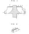
- a radial flow turbine rotor which comprises a conical shaft 1 and a plurality of blades 2 projecting from the periphery of the shaft and inclined with respect to the axis of the shaft.
- the shaft 1 and blades 2 are integrally formed from a ceramic material by injection molding.
- each projection 5 has a substantially triangular cross section and is about 0.5 - 1.0 mm high and wide.
- the molding thus obtained is then sintered, and projections 5 formed on blade edges (6) facing a casing (not shown) are removed by grinding while leaving projections 5 formed on inlet and outlet edges 3 and 4 of the blades 2 facing a passage of fluid such as combustion exhaust gas (the direction of flow of fluid being shown by arrows).
- the numeral 7 is a shaft connected to the shaft 1.
- the radial flow turbine rotor of the above construction which is a one-piece sintered ceramic body having the shaft and blades formed intergrally by injection molding, has high mechanical strength at high temperatures. Also, its specific weight is low so that it is light in weight. Thus, its blade stems will not be'broken due to vibration stress or rotational moment. Further, since the projections are formed on the blade edges facing the fluid passage and a fluid is guided along the projections, the loss of fluid energy can be reduced to increase turbine efficiency. Further, since the injection molding is done using a mold which has parting lines corresponding to the blade edges, no burrs are formed on the periphery of the shaft, so that only the edges of the blades that are facing the casing can be ground after sintering. Thus, the time required for grinding can be greatly reduced.
- a powder mixture consisting of 84% by weight of silicon nitride, 6% by weight of yttrium oxide and 10% by weight of aluminum oxide, the mean particle size thereof being 1.1, 1.2 and 0.5 microns respectively, was used.
- a thermoplastic organic material was used for the binder.
- the proportion of the organic binder should be as small as possible for it must be removed in the subsequent step.
- the volume ratio of the ceramic material to the organic binder ranges from about 70 : 30 to 50 : 50. In this example, it was set at 60 : 40.
- the ceramic material and binder were kneaded together while heating the system to a temperature of about 150° at which the binder was fused.
- the paste thus obtained was used for injection molding with an injection pressure of about 500 kg/cm 2 .
- the injection pressure desirably ranges from about 50 to 1,000 kg/cm .
- the molding was gradually heated to remove the binder through decomposition and evaporation. At this time, deformation of the molding and formation of cracks in the molding are prone, if the rate of temperature rise is low. For this reason, it is desirable to raise the temperature to about 500 to 1,200°C at a rate of about 0.5 to 20°C/hr. In this example, the heating was done at a rate of about 5°C/hr to raise the temperature to about 800°C. After the binder had been completely removed, sintering was done.
- Sintering is desirably done by heating the molding in an inert gas such as nitrogen gas at a temperature of about 1,650 to 1,800°C to prevent oxidation.
- the sintering was done by holding the molding in a nitrogen gas at about 1,750°C for four hours.
- the blade edges which are facing the casing were ground with a #200 diamond grindstone to obtain the product.
- the grindstone usually has a grain size ranging from #100 to #600.
- the specific gravity and the liner thermal expansion coefficient of the ceramic materials obtained were 3.20 g/cc and 3.1 x 10 6 /°C respectively.
- the flexural strengths were 75 kg/mm 2 at room temperature, 75 kg/mm 2 at 700°C and 71 kg/mm2 at 1,000°C.
- the radial flow turbine rotor made by this example helps enhance the turbine efficiency. Further the grinding time after the sintering was reduced to one half compared to the prior art method of manufacture.
Landscapes
- Engineering & Computer Science (AREA)
- Mechanical Engineering (AREA)
- General Engineering & Computer Science (AREA)
- Chemical & Material Sciences (AREA)
- Ceramic Engineering (AREA)
- Materials Engineering (AREA)
- Turbine Rotor Nozzle Sealing (AREA)
- Ceramic Products (AREA)
- Structures Of Non-Positive Displacement Pumps (AREA)
Applications Claiming Priority (2)
| Application Number | Priority Date | Filing Date | Title |
|---|---|---|---|
| JP56190597A JPS5893992A (ja) | 1981-11-30 | 1981-11-30 | 軸流回転装置およびその製造方法 |
| JP190597/81 | 1981-11-30 |
Publications (3)
| Publication Number | Publication Date |
|---|---|
| EP0080800A2 true EP0080800A2 (de) | 1983-06-08 |
| EP0080800A3 EP0080800A3 (en) | 1983-11-02 |
| EP0080800B1 EP0080800B1 (de) | 1987-03-25 |
Family
ID=16260708
Family Applications (1)
| Application Number | Title | Priority Date | Filing Date |
|---|---|---|---|
| EP82305225A Expired EP0080800B1 (de) | 1981-11-30 | 1982-09-30 | Verfahren zur Herstellung eines keramischen Radialturbinenläufers |
Country Status (4)
| Country | Link |
|---|---|
| US (1) | US4597926A (de) |
| EP (1) | EP0080800B1 (de) |
| JP (1) | JPS5893992A (de) |
| DE (1) | DE3275845D1 (de) |
Families Citing this family (10)
| Publication number | Priority date | Publication date | Assignee | Title |
|---|---|---|---|---|
| JPS6060299A (ja) * | 1983-09-10 | 1985-04-06 | Agency Of Ind Science & Technol | 耐熱性フアン |
| JPS61291702A (ja) * | 1985-06-18 | 1986-12-22 | Toyota Central Res & Dev Lab Inc | 熱機関用回転体およびその製造方法 |
| US5746960A (en) * | 1988-04-15 | 1998-05-05 | Citizen Watch Co., Ltd. | Method of manufacturing powder injection molded part |
| JPH0686815B2 (ja) * | 1990-01-17 | 1994-11-02 | 日本碍子株式会社 | セラミックターボチャージャロータの製造方法 |
| EP0573207A1 (de) * | 1992-06-02 | 1993-12-08 | Certech Incorporated | Spritzgegossener Gegenstand und Verfahren zur dessen Herstellung |
| US6447254B1 (en) * | 2001-05-18 | 2002-09-10 | Sikorsky Aircraft Corporation | Low dieletric constant erosion resistant material |
| JP3534730B2 (ja) | 2001-12-10 | 2004-06-07 | 三菱重工業株式会社 | ラジアルタービンの動翼 |
| US6742989B2 (en) * | 2001-10-19 | 2004-06-01 | Mitsubishi Heavy Industries, Ltd. | Structures of turbine scroll and blades |
| JP2016156302A (ja) * | 2015-02-24 | 2016-09-01 | 三菱重工業株式会社 | 羽根車 |
| ITUB20160544A1 (it) * | 2016-01-19 | 2017-07-19 | Luciano Cinotti | Pompa di circolazione primaria per reattore nucleare con albero a profilo assiale ottimizzato |
Family Cites Families (10)
| Publication number | Priority date | Publication date | Assignee | Title |
|---|---|---|---|---|
| US2431660A (en) * | 1944-12-01 | 1947-11-25 | Bbc Brown Boveri & Cie | Turbine blade |
| FR1236779A (fr) * | 1959-09-24 | 1960-07-22 | Birmingham Small Arms Co Ltd | Profilage des aubages de turbines à gaz |
| US3133505A (en) * | 1959-12-01 | 1964-05-19 | Siemen & Hinsch Gmbh | Impeller wheel |
| US3077297A (en) * | 1960-10-24 | 1963-02-12 | Stalker Corp | Bladed rotors |
| US3430898A (en) * | 1967-05-01 | 1969-03-04 | Us Navy | Leading edge for hypersonic vehicle |
| GB1318526A (en) * | 1969-11-28 | 1973-05-31 | Cav Ltd | Rotor assemblies |
| US4175911A (en) * | 1975-06-20 | 1979-11-27 | Daimler-Benz Aktiengesellschaft | Radial turbine wheel for a gas turbine |
| JPS5623503A (en) * | 1979-08-02 | 1981-03-05 | Toshiba Corp | Supercharger |
| JPS5667206A (en) * | 1979-11-02 | 1981-06-06 | Ngk Spark Plug Co | Manufacture of ceramic rotor |
| US4408959A (en) * | 1980-07-03 | 1983-10-11 | Kennecott Corporation | Ceramic radial turbine wheel |
-
1981
- 1981-11-30 JP JP56190597A patent/JPS5893992A/ja active Pending
-
1982
- 1982-09-30 DE DE8282305225T patent/DE3275845D1/de not_active Expired
- 1982-09-30 EP EP82305225A patent/EP0080800B1/de not_active Expired
-
1985
- 1985-03-13 US US06/711,092 patent/US4597926A/en not_active Expired - Fee Related
Also Published As
| Publication number | Publication date |
|---|---|
| EP0080800B1 (de) | 1987-03-25 |
| JPS5893992A (ja) | 1983-06-03 |
| DE3275845D1 (en) | 1987-04-30 |
| EP0080800A3 (en) | 1983-11-02 |
| US4597926A (en) | 1986-07-01 |
Similar Documents
| Publication | Publication Date | Title |
|---|---|---|
| US3905723A (en) | Composite ceramic turbine rotor | |
| EP0052913B1 (de) | Keramischer Rotor | |
| US4597926A (en) | Method of manufacturing radial flow turbine rotor | |
| JP6979761B2 (ja) | セラミックマトリックス複合材構成要素及びセラミックマトリックス複合材 | |
| US10961855B2 (en) | Ceramic matrix composite component cooling | |
| US4385866A (en) | Curved blade rotor for a turbo supercharger | |
| JPS6224603B2 (de) | ||
| JP2017105698A5 (de) | ||
| EP0095540B1 (de) | Keramischer Rotor | |
| CN108730039B (zh) | 用于燃气涡轮发动机的涡轮喷嘴段和系统 | |
| JPS5925083B2 (ja) | ラジアルタ−ビンロ−タ | |
| EP0117721B1 (de) | Herstellungsweise für einen keramischen Radialturbinenrotor | |
| US5051062A (en) | Radial flow turbine rotor | |
| US4692099A (en) | Rotary component of a rotary device for heat engines and a method of manufacturing the same | |
| WO1991015438A1 (fr) | Element ceramique pour temperatures elevees | |
| JPS6411444B2 (de) | ||
| US4544327A (en) | Ceramic rotor and manufacturing process therefor | |
| US5476623A (en) | Method of manufacturing hollow ceramic part with hole therein | |
| EP0112146A2 (de) | Keramischer Rotor und Verfahren zur Herstellung | |
| EP3775495A1 (de) | Axiale aussenläuferturbine und verfahren zurherstellung eines rotorabschnitts dieser turbine | |
| JPS62228602A (ja) | 熱機関用回転体 | |
| JP3176190B2 (ja) | セラミックタービンローター | |
| US11286783B2 (en) | Airfoil with CMC liner and multi-piece monolithic ceramic shell | |
| JPS61215401A (ja) | 過給機のタ−ビンホイ−ル | |
| JPS6079102A (ja) | セラミツクタ−ビンロ−タ |
Legal Events
| Date | Code | Title | Description |
|---|---|---|---|
| PUAI | Public reference made under article 153(3) epc to a published international application that has entered the european phase |
Free format text: ORIGINAL CODE: 0009012 |
|
| 17P | Request for examination filed |
Effective date: 19821013 |
|
| AK | Designated contracting states |
Designated state(s): DE FR GB SE |
|
| PUAL | Search report despatched |
Free format text: ORIGINAL CODE: 0009013 |
|
| AK | Designated contracting states |
Designated state(s): DE FR GB SE |
|
| RAP1 | Party data changed (applicant data changed or rights of an application transferred) |
Owner name: KABUSHIKI KAISHA TOSHIBA |
|
| GRAA | (expected) grant |
Free format text: ORIGINAL CODE: 0009210 |
|
| AK | Designated contracting states |
Kind code of ref document: B1 Designated state(s): DE FR GB SE |
|
| ET | Fr: translation filed | ||
| REF | Corresponds to: |
Ref document number: 3275845 Country of ref document: DE Date of ref document: 19870430 |
|
| PLBE | No opposition filed within time limit |
Free format text: ORIGINAL CODE: 0009261 |
|
| STAA | Information on the status of an ep patent application or granted ep patent |
Free format text: STATUS: NO OPPOSITION FILED WITHIN TIME LIMIT |
|
| 26N | No opposition filed | ||
| PGFP | Annual fee paid to national office [announced via postgrant information from national office to epo] |
Ref country code: GB Payment date: 19910806 Year of fee payment: 10 |
|
| PGFP | Annual fee paid to national office [announced via postgrant information from national office to epo] |
Ref country code: DE Payment date: 19910930 Year of fee payment: 10 |
|
| PGFP | Annual fee paid to national office [announced via postgrant information from national office to epo] |
Ref country code: FR Payment date: 19920909 Year of fee payment: 11 |
|
| PG25 | Lapsed in a contracting state [announced via postgrant information from national office to epo] |
Ref country code: GB Effective date: 19920930 |
|
| GBPC | Gb: european patent ceased through non-payment of renewal fee |
Effective date: 19920930 |
|
| PG25 | Lapsed in a contracting state [announced via postgrant information from national office to epo] |
Ref country code: DE Effective date: 19930602 |
|
| PGFP | Annual fee paid to national office [announced via postgrant information from national office to epo] |
Ref country code: SE Payment date: 19930917 Year of fee payment: 12 |
|
| PG25 | Lapsed in a contracting state [announced via postgrant information from national office to epo] |
Ref country code: FR Free format text: LAPSE BECAUSE OF NON-PAYMENT OF DUE FEES Effective date: 19940531 |
|
| REG | Reference to a national code |
Ref country code: FR Ref legal event code: ST |
|
| PG25 | Lapsed in a contracting state [announced via postgrant information from national office to epo] |
Ref country code: SE Effective date: 19941001 |
|
| EAL | Se: european patent in force in sweden |
Ref document number: 82305225.3 |
|
| EUG | Se: european patent has lapsed |
Ref document number: 82305225.3 |