EP0080807A2 - Adaptateur pour le montage d'un interrupteur sur un panneau - Google Patents
Adaptateur pour le montage d'un interrupteur sur un panneau Download PDFInfo
- Publication number
- EP0080807A2 EP0080807A2 EP82305729A EP82305729A EP0080807A2 EP 0080807 A2 EP0080807 A2 EP 0080807A2 EP 82305729 A EP82305729 A EP 82305729A EP 82305729 A EP82305729 A EP 82305729A EP 0080807 A2 EP0080807 A2 EP 0080807A2
- Authority
- EP
- European Patent Office
- Prior art keywords
- adapter
- hole
- cylindrical portion
- flange
- inner diameter
- Prior art date
- Legal status (The legal status is an assumption and is not a legal conclusion. Google has not performed a legal analysis and makes no representation as to the accuracy of the status listed.)
- Granted
Links
Images


Classifications
-
- H—ELECTRICITY
- H02—GENERATION; CONVERSION OR DISTRIBUTION OF ELECTRIC POWER
- H02B—BOARDS, SUBSTATIONS OR SWITCHING ARRANGEMENTS FOR THE SUPPLY OR DISTRIBUTION OF ELECTRIC POWER
- H02B1/00—Frameworks, boards, panels, desks, casings; Details of substations or switching arrangements
- H02B1/015—Boards, panels, desks; Parts thereof or accessories therefor
- H02B1/04—Mounting thereon of switches or of other devices in general, the switch or device having, or being without, casing
- H02B1/044—Mounting through openings
Definitions
- the present invention relates to an adaptor for mounting a switch onto a panel, and, particularly to an adapter for use when an actuating switch such as a push-botton switch is to be mounted onto a panel in such a manner that a cylindrical portion of the switch is penetrated a panel through a hole previously formed in the panel and fixed to the panel by appro- preate means such as a screw and when the outer diameter of the cylindrical portion is smaller than that is suited for the hole.
- the outer diameter of the cylindrical portion of the switch is standardized by their own domestic standard or the like for affording convenience in use as well as in manufacturing such switches. Further, there is a case where various values are set as the diameter by the domestic standard. For example, two kinds of values, 30 mm and 25 mm, are set in Japan and a value, 22 mm, is set in Europe, as the standardized outer diameter of the cylindrical portion of an industrial-purpose actuating switch. Thus, in a world-wide sense, there are various kinds of standardized values for the outer diameter of the cylindrical portion of the actuating switches.
- the inner diameter of a hole previously formed in a panel for mounting an actuating switch has to be set with selected one of various kinds of standardized values.
- an object of the present invention is provide an adaptor for properly mounting an actuating switch having a cylindrical portion the outer diameter of which is smaller than the inner diameter of a hole proviously formed in a panel to which the switch be mounted.
- an adapter for enabling an actuating switch which has a contact section and an actuating section movably accommodating therein an actuator for actuating the contact section and which is so arranged that a first hollow cylindrical portion constituting a part of the actuating section and axially movably accommodating therein the actuator can be directly mounted in a first hole having a first predetermined inner diameter and previously formed in a panel, to be mounted through the adapter into a second hole having a second predetermined inner diameter and previously formed in the or another panel.
- This adapter comprises first means for engaging with the actuating section and second means for engaging with the panel through the second hole.
- an actuating switch such as a push button switch, an illumination type push button switch, a cam switch or the like, has a construction in which a given number of stacked contact sections 20 are coupled with a switch actuating section 10 having a rear box-like portion 12 and a cylindrical portion 14 projecting upward from the box-like portion 12, as shown in Fig. 1.
- the cylindrical portion 14 When such an acttuating section 10 is mounted onto a panel 30, the cylindrical portion 14 is inserted from the back side of the panel 30 into a mounting hole 32 previously formed in the panel 30 and having an inner diameter which is substantially equal to the outer diameter of the cylindrical portion but a little larger than the latter to enable the latter to loosely pass through the hole, with packing rings 34 disposed between the upper side shoulder portion of the rear box-like portion 12 and the back surface of the panel 30. Then, the top portion of the cylindrical portion 14 is screwed up by a cap 50 from the front side of the panel 30.
- FIGs. 2 and 3 an embodiment of an adapter according to the invention for mounting an actuating section of a switch onto a panel is shown in combination with such an actuating switch.
- the adapter 40 has a flange portion 42 and a cylindrical portion 44 projecting from the flange portion 42 substantially at the central portion of the flange portion 42.
- an inner thread 46 is provided so that it may engage with an external thread 16 formed in the outer surface of the cylindrical portion 14 of the actuating section 10.
- an external thread 48 is formed so that it may engage with an inner thread formed in the inner surface of the cap 50.
- a suitable engaging means such as guiding grooves (not shown) may be formed at the outer surface of the cylindrical portion 44 in place of the external thread 48, if the cap 50 is of an insert engaging type.
- a suitable engaging means such as guiding grooves (not shown) may be formed at the outer surface of the cylindrical portion 44 in place of the external thread 48, if the cap 50 is of an insert engaging type.
- Fig. 4 shows another embodiment of the present invention in which the same numerals as those used in Figs. 1 to 3 designate elements or parts having the same functions and numerals accompanied by a prime designate elements or parts having similar functions.
- an external thread 16' and another external thread 16" which are different from each other in diameter are respectively formed at the top and root portions of the cyrindrical portion 14 on one hand, and only an inner thread 46' which may engage with the larger diameter external thread 16' is formed in the inner surface of the adapter 40.
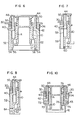
- Figs. 5 and 6 show still another embodiment of the present invention, in which the same numerals as those used in Figs. 1 to 3 designate elements or parts having the same functions and numerals accompanied by a prime designate elements or parts having similar functions.
- FIG. 2 and 3 This embodiment is different from that shown in Figs. 2 and 3 only in the engagement means between the actuating section 10 and the adapter 40, while it is quite the same as the latter in other points. That is, in the embodiment of Figs. 2 and 3, the adapter 40 is provided with a rectangular flat flange portion 42 with the cylindrical portion 44 projecting from the upper surface of the flange portion 42, while in this embodiment of Figs. 2 and 3, an adapter 40 is provided with not only a rectangular flat flange portion 42 with a cylindrical portion 44 projecting from the upper surface of the flange portion 42 but also a pair of opposing legs 52 projecting downward from the lower surface of the flange portion 42 at the opposite ends of the same, respectively.
- a projecting hook-like engaging portion 54 is formed at the lower inner side of each of these legs 52. In this case, therefore, no thread is provided in the inner surface of the cylindrical portion 44.
- an external thread 48 is provided in the outer surface of the forward end portion of the cylindrical portion 44 for engaging with the inner thread of the cap 50.
- guide grooves may be formed for insert engagement in place of the external thread 48.
- the opposing legs 52 of the adapter 40 are outwardly urged to widen the distance therebetween against their elasticity and then, being maintained in this state, they are pushed on along the opposite side walls of the rear box-like portion 12 of the actuating section 10 until their hook-like engaging portions 54 have respectively engaged with groove-like recessed engaging portions 56 correspondingly formed on the outer side walls of the box-like portion 12.
- the adapter 40 has been elastically fixed on the actuating section 10.
- the adapter 40 may be entirely made of a resin material, the adapter will be expensive because it is necessary to use a soft resin material in order to provide elasticity.
- a stainless engaging members 58 provided with hook-like engaging portions 60 at their lower ends may be attached to the respective legs 52, as shown in Fig. 7, so that the other portions of the adapter may be made of a relatively inexpensive hard resin material.
- hook-like protrusions 62 may be formed, as shown in Fig. 8, as the engaging portion of the actuating section 10 in place of the groove-like engaging portions 56, and grooves 64 may be formed on the respective legs 52 of the adapter 40 to engage with these hook-like protrusions 62.
- the actuating section 10 with the adapter 40 attached thereto may be mounted onto the panel 30 in quite the same manner as that already described and therefore detailed description thereabout will be omitted.
- Figs. 9 and 10 show a further embodiment of the present invention, in which the same numerals as those used in Figs. 1 to 3 designate elements or parts having the same functions.
- an adapter 40 may be coupled with an actuating section 10 through an intermediate member 70.
- This adapter 40 is made of a metal material, such as zinc die-casting or alminium die-casting, and has a flat flange portion 42 and a cylindrical portion 44 projecting from the upper surface of the flange 42 at its substantially central portion.
- an external thread 46 is formed for engaging with a cap 50, or alternatively guide grooves (not shown) may be formed if the cap 50 is of an inserted engaging type.
- the inter-mediate member 70 has the flat flange portion 72 and a cylindrical portion 76 projecting from the upper surface of the flange portion 72 at its substantially central portion.
- the inner diameter of this cylindrical portion 76 is made to be slightly larger than the outer diameter of the cylindrical portion 14 of the actuating section 10 so that the cylindrical portion 76 of the intermediate member 70 may be attached to the actuating section 10 from the outside thereof. Further, the outer diameter of the cylindrical portion 76 is made slightly smaller than the inner diameter of the cylindrical portion 44 of the adapter 40.
- An inner thread 78 is formed at the lower inner surface of the cylindrical portion 76 so that it may engage with an external thread 16 formed in the outer surface of the cylindrical portion 14 of the actuating section 10.
- Figs. 11 to 13 show a further embodiment of the present invention, in which the same numerals as those used in Figs. 1 to 3 designate elements or parts having the same functions and numerals with a prime designate elements or parts having similar functions.
- an adapter 40' has a flange portion 42' which is formed at its substantially central portion with a through hole 80 which a cylindrical portion 14 of an actuating section 10 may pass.
- the flange portion 42' is further formed with downwardly projecting step portions 82 at the lower surface thereof.
- various adaptors respectively having various outer diameters such as d 2 , d 3 , d 4 , at the projecting step portions 82, as shown in Fig. 12. These values d 2 , d3, d 4 ... of the diameter are made to be agreed with the values previously defined by any standard.
- the projecting step portions 82 may be made to be a single continuous annular step portion (not shown) formed in the circumferential direction along the entire periphery of the through hole 80, or alternatively may includes at least two step portions formed discretely at equal distances as shown in Fig. 13.
- one of the various adaptors having an outer diameter at its projecting set portion 82 which may agree with the diameter of a mounting hole 32 formed in a panel 30 to which hole the actuating switch is to be attached.
- the cylindrical portion 14 is inserted into the mounting hole 32 from the back of the panel 30.
- the adapter 40' is inserted from the front side of the panel 30 with its step portion 82 underside onto the cylindrical portion 14 which has been projected from the front surface of the panel 30 and then the cap 50 is attached to the cylindrical portion 14 from the front side of the adapter 40 so as to fasten the actuating section 10 of the switch.
- the outer periphery of the step portion 82 of the adapter 40' is made to abut on the inner periphery of the mounting hole 32 and at the same time the lower surface of the flange portion 42' is made to abut on the front surface of the panel 30.
- the adapter 40' is disposed.between the actuating section 10 and the panel 30 and fixed to the panel together with the actuating section 10.
- the thickness of the projecting step portion 82 is preferably selected to be equal or thiner than the thickness of the panel 30, it is not always limited to this and may be selected to be thicker than the thickness of the panel 30. In the latter case, it will do to make the inner diameter of the uppermost ring packing 34 to be larger than the outer diameter of the step portion 82.
Landscapes
- Engineering & Computer Science (AREA)
- Power Engineering (AREA)
- Switch Cases, Indication, And Locking (AREA)
Applications Claiming Priority (8)
| Application Number | Priority Date | Filing Date | Title |
|---|---|---|---|
| JP17997281U JPS5883716U (ja) | 1981-12-02 | 1981-12-02 | 操作スイツチ本体のパネル取り付け用アダプタ |
| JP179971/81U | 1981-12-02 | ||
| JP179970/81U | 1981-12-02 | ||
| JP17997181U JPS5883715U (ja) | 1981-12-02 | 1981-12-02 | 操作スイツチ本体のパネル取り付け用アダプタ |
| JP179972/81U | 1981-12-02 | ||
| JP17997081U JPS5883714U (ja) | 1981-12-02 | 1981-12-02 | 操作スイツチ本体のパネル取り付け用アダプタ |
| JP64665/82U | 1982-04-30 | ||
| JP6466582U JPS58165918U (ja) | 1982-04-30 | 1982-04-30 | 操作スイツチ本体のパネル取り付け装置 |
Publications (3)
| Publication Number | Publication Date |
|---|---|
| EP0080807A2 true EP0080807A2 (fr) | 1983-06-08 |
| EP0080807A3 EP0080807A3 (en) | 1985-04-10 |
| EP0080807B1 EP0080807B1 (fr) | 1988-06-01 |
Family
ID=27464470
Family Applications (1)
| Application Number | Title | Priority Date | Filing Date |
|---|---|---|---|
| EP82305729A Expired EP0080807B1 (fr) | 1981-12-02 | 1982-10-28 | Adaptateur pour le montage d'un interrupteur sur un panneau |
Country Status (3)
| Country | Link |
|---|---|
| US (1) | US4499352A (fr) |
| EP (1) | EP0080807B1 (fr) |
| DE (1) | DE3278610D1 (fr) |
Cited By (4)
| Publication number | Priority date | Publication date | Assignee | Title |
|---|---|---|---|---|
| FR2598264A1 (fr) * | 1986-05-02 | 1987-11-06 | Telemecanique Electrique | Dispositif pour la fixation concentrique d'un organe de commande ou de signalisation dans une ouverture superieure a son diametre nominal. |
| FR2604559A1 (fr) * | 1986-09-26 | 1988-04-01 | Legrand Sa | Dispositif de commande pour materiel electrique antideflagrant |
| EP0257208A3 (en) * | 1986-06-30 | 1989-07-26 | Schunk Metall Und Kunststoff Gmbh | Head for control- and/or signal devices for front mounting on panels |
| EP0335838A3 (fr) * | 1988-03-29 | 1991-01-23 | TSCHUDIN & HEID AG | Equipement avec un support et au moins un dispositif électrique de commutation présentant un élément piézoélectrique |
Families Citing this family (11)
| Publication number | Priority date | Publication date | Assignee | Title |
|---|---|---|---|---|
| US4742198A (en) * | 1986-12-09 | 1988-05-03 | Adams Elevator Equipment Co. | Push button assembly having an actuator subassembly fixed to the innerside of a face plate |
| US4892987A (en) * | 1989-01-23 | 1990-01-09 | White Consolidated Industries, Inc. | Mounting for electrical control |
| US5150092A (en) * | 1991-03-06 | 1992-09-22 | Eaton Corporation | Control button adaptor for electric control apparatus |
| ATE149735T1 (de) * | 1991-12-24 | 1997-03-15 | Inventio Ag | Befehls- und meldegerät |
| US5382766A (en) * | 1993-07-29 | 1995-01-17 | Emerson Electric Co. | Shock resistant switch mounting |
| US5881864A (en) * | 1997-11-24 | 1999-03-16 | Shelhorse; Randy M. | Decorative doorbell mounting assembly |
| DE19959339A1 (de) * | 1999-12-09 | 2001-06-21 | Ellenberger & Poensgen | Elektrisches Funktionsgerät, insbesondere Schutzschalter, zum Einsatz in der Luftfahrt |
| US8698027B2 (en) * | 2011-08-04 | 2014-04-15 | Stencil Cutting and Supply Co., Inc. | Pushbutton switch |
| EP2852014B1 (fr) * | 2013-09-20 | 2023-09-06 | Siemens Aktiengesellschaft | Appareil de commande et de signalisation doté d'un montage encastré en façade |
| CN109119270A (zh) * | 2018-11-12 | 2019-01-01 | 珠海格力电器股份有限公司 | 按键及设有其的电器 |
| CA3143531A1 (fr) * | 2019-08-28 | 2021-03-04 | Idd Aerospace Corporation | Ensemble panneau de commutation a faible profil |
Family Cites Families (10)
| Publication number | Priority date | Publication date | Assignee | Title |
|---|---|---|---|---|
| US1106488A (en) * | 1912-04-18 | 1914-08-11 | Andrew J Callaghan | Valve. |
| GB307173A (en) * | 1928-01-31 | 1929-03-07 | Charles Leonard Arnold | Improvements in or relating to methods of insulating the exposed parts of the metal bridge of the tumbler type of electric switch |
| US2523125A (en) * | 1946-10-30 | 1950-09-19 | Westinghouse Electric Corp | Switch |
| GB741926A (en) * | 1952-03-27 | 1955-12-14 | Walsall Conduits Ltd | Improvements relating to dolly-operated electric switches |
| FR1135111A (fr) * | 1955-11-03 | 1957-04-24 | Dispositif formant support de travail et appareils électriques munis de ce dispositif | |
| US3876277A (en) * | 1973-06-25 | 1975-04-08 | Bunker Ramo | Connector assembly having flush mount adapter |
| US4179038A (en) * | 1977-03-07 | 1979-12-18 | Rosan Engineering Corp. | Self-sealing flange and method of installation thereof |
| DE7712781U1 (de) * | 1977-04-22 | 1977-08-04 | Siemens Ag, 1000 Berlin Und 8000 Muenchen | Rosette mit Frontring |
| US4154125A (en) * | 1977-07-05 | 1979-05-15 | Beckman Instruments, Inc. | Knob locking and drag device |
| US4186762A (en) * | 1978-09-18 | 1980-02-05 | Robertshaw Controls Company | Control device mounting means and parts therefor |
-
1982
- 1982-10-26 US US06/436,888 patent/US4499352A/en not_active Expired - Fee Related
- 1982-10-28 DE DE8282305729T patent/DE3278610D1/de not_active Expired
- 1982-10-28 EP EP82305729A patent/EP0080807B1/fr not_active Expired
Cited By (4)
| Publication number | Priority date | Publication date | Assignee | Title |
|---|---|---|---|---|
| FR2598264A1 (fr) * | 1986-05-02 | 1987-11-06 | Telemecanique Electrique | Dispositif pour la fixation concentrique d'un organe de commande ou de signalisation dans une ouverture superieure a son diametre nominal. |
| EP0257208A3 (en) * | 1986-06-30 | 1989-07-26 | Schunk Metall Und Kunststoff Gmbh | Head for control- and/or signal devices for front mounting on panels |
| FR2604559A1 (fr) * | 1986-09-26 | 1988-04-01 | Legrand Sa | Dispositif de commande pour materiel electrique antideflagrant |
| EP0335838A3 (fr) * | 1988-03-29 | 1991-01-23 | TSCHUDIN & HEID AG | Equipement avec un support et au moins un dispositif électrique de commutation présentant un élément piézoélectrique |
Also Published As
| Publication number | Publication date |
|---|---|
| EP0080807A3 (en) | 1985-04-10 |
| DE3278610T2 (fr) | 1988-07-07 |
| DE3278610D1 (en) | 1988-07-07 |
| EP0080807B1 (fr) | 1988-06-01 |
| US4499352A (en) | 1985-02-12 |
Similar Documents
| Publication | Publication Date | Title |
|---|---|---|
| EP0080807A2 (fr) | Adaptateur pour le montage d'un interrupteur sur un panneau | |
| US4453059A (en) | Mounting device for switches or the like | |
| US6088531A (en) | Water-resistant push button switch | |
| US5975323A (en) | Extender for electrical box | |
| US6386005B1 (en) | Combination lock | |
| US4225758A (en) | Switch operated axially or rotatably | |
| JPH0528702Y2 (fr) | ||
| GB2091369A (en) | Screw retention and alignment | |
| US4774645A (en) | Replaceable lamp bulb assembly | |
| US20020163812A1 (en) | Fast assembling structure for ceiling fan lamp and ceiling fan | |
| US4428034A (en) | Light bulb mounting unit | |
| US3967432A (en) | Panel edge fastener receptacle and joint | |
| US3828291A (en) | Protector for electric circuit | |
| US3246320A (en) | Mounting for pilot light | |
| KR940003866Y1 (ko) | 플라스틱제 리벳 | |
| GB2303667A (en) | Releasable socket fastener | |
| US4505596A (en) | Composable wall-clock | |
| EP0063355B1 (fr) | Dispositif de réglage de temps pour interrupteur horaire | |
| JPH08153627A (ja) | 雑音吸収具 | |
| US6903283B2 (en) | Plunger retention apparatus and method for switch enclosures | |
| JP2500662B2 (ja) | 積み重ね式スタッド | |
| JP2872091B2 (ja) | 携帯用受信機の筐体構造 | |
| JP2575246Y2 (ja) | ロータリエンコーダ | |
| EP0446487A1 (fr) | Interrupteur à bouton poussoir avec un capuchon à lentille serré au-dessus du bouton | |
| KR0122745Y1 (ko) | 판재의 홀록크장치 |
Legal Events
| Date | Code | Title | Description |
|---|---|---|---|
| PUAI | Public reference made under article 153(3) epc to a published international application that has entered the european phase |
Free format text: ORIGINAL CODE: 0009012 |
|
| AK | Designated contracting states |
Designated state(s): DE FR GB IT |
|
| PUAL | Search report despatched |
Free format text: ORIGINAL CODE: 0009013 |
|
| AK | Designated contracting states |
Designated state(s): DE FR GB IT |
|
| 17P | Request for examination filed |
Effective date: 19850913 |
|
| 17Q | First examination report despatched |
Effective date: 19861009 |
|
| ITF | It: translation for a ep patent filed | ||
| GRAA | (expected) grant |
Free format text: ORIGINAL CODE: 0009210 |
|
| AK | Designated contracting states |
Kind code of ref document: B1 Designated state(s): DE FR GB IT |
|
| REF | Corresponds to: |
Ref document number: 3278610 Country of ref document: DE Date of ref document: 19880707 |
|
| ET | Fr: translation filed | ||
| PLBE | No opposition filed within time limit |
Free format text: ORIGINAL CODE: 0009261 |
|
| STAA | Information on the status of an ep patent application or granted ep patent |
Free format text: STATUS: NO OPPOSITION FILED WITHIN TIME LIMIT |
|
| 26N | No opposition filed | ||
| ITTA | It: last paid annual fee | ||
| PGFP | Annual fee paid to national office [announced via postgrant information from national office to epo] |
Ref country code: FR Payment date: 19970822 Year of fee payment: 16 |
|
| PGFP | Annual fee paid to national office [announced via postgrant information from national office to epo] |
Ref country code: GB Payment date: 19971020 Year of fee payment: 16 |
|
| PGFP | Annual fee paid to national office [announced via postgrant information from national office to epo] |
Ref country code: DE Payment date: 19971222 Year of fee payment: 16 |
|
| PG25 | Lapsed in a contracting state [announced via postgrant information from national office to epo] |
Ref country code: GB Free format text: LAPSE BECAUSE OF NON-PAYMENT OF DUE FEES Effective date: 19981028 |
|
| GBPC | Gb: european patent ceased through non-payment of renewal fee |
Effective date: 19981028 |
|
| PG25 | Lapsed in a contracting state [announced via postgrant information from national office to epo] |
Ref country code: FR Free format text: LAPSE BECAUSE OF NON-PAYMENT OF DUE FEES Effective date: 19990630 |
|
| REG | Reference to a national code |
Ref country code: FR Ref legal event code: ST |
|
| PG25 | Lapsed in a contracting state [announced via postgrant information from national office to epo] |
Ref country code: DE Free format text: LAPSE BECAUSE OF NON-PAYMENT OF DUE FEES Effective date: 19990803 |