EP0080978A2 - Standardisierte Anlage für die Oberflächenbehandlung von Metallrohren durch Vorheizen, Reinigen, Lackieren, Trocknen und Markieren - Google Patents
Standardisierte Anlage für die Oberflächenbehandlung von Metallrohren durch Vorheizen, Reinigen, Lackieren, Trocknen und Markieren Download PDFInfo
- Publication number
- EP0080978A2 EP0080978A2 EP82830247A EP82830247A EP0080978A2 EP 0080978 A2 EP0080978 A2 EP 0080978A2 EP 82830247 A EP82830247 A EP 82830247A EP 82830247 A EP82830247 A EP 82830247A EP 0080978 A2 EP0080978 A2 EP 0080978A2
- Authority
- EP
- European Patent Office
- Prior art keywords
- tubes
- station
- painting
- transfer
- plant
- Prior art date
- Legal status (The legal status is an assumption and is not a legal conclusion. Google has not performed a legal analysis and makes no representation as to the accuracy of the status listed.)
- Granted
Links
Images







Classifications
-
- B—PERFORMING OPERATIONS; TRANSPORTING
- B05—SPRAYING OR ATOMISING IN GENERAL; APPLYING FLUENT MATERIALS TO SURFACES, IN GENERAL
- B05B—SPRAYING APPARATUS; ATOMISING APPARATUS; NOZZLES
- B05B13/00—Machines or plants for applying liquids or other fluent materials to surfaces of objects or other work by spraying, not covered by groups B05B1/00 - B05B11/00
- B05B13/02—Means for supporting work; Arrangement or mounting of spray heads; Adaptation or arrangement of means for feeding work
- B05B13/0207—Means for supporting work; Arrangement or mounting of spray heads; Adaptation or arrangement of means for feeding work the work being an elongated body, e.g. wire or pipe
Definitions
- the present invention is related to a standardized line plant for the automatic surface treatment of preheating, brushing, painting, drying and marking of metallic tubes.
- These tubes generally present a 100 to 400 mm. diameter and a length from 3 to 20 m, said dimensioning not being anyway restrictive but only suggested for the purposes of individuating the problem.
- the purpose of the present invention is to provide a remedy for these difficulties and, as characterized in the claims, it solves the problem realizing a surface treatment line according to the required purpose, operating in a completely automatic way and treating at the same time a large number of tubes which proceed parallely along the treatment line from a loading station to an unloading station in which the set of tubes is subjected during its advancing along the treatment line, first to detecting and memorizing, by means of a data detecting electronic station, the outside size (tube diameter and length), tube position and number of. advancing set and, by means of a computer, make use of said data for the tube treatment in the next stations in uniform way, being said stations of preheating, brushing, painting, drying, marking and unloading respectively.
- the line includes a transversal loading station and a transversal unloading station-placed at the respective ends, being the loading line situated immediately upstream the detecting data station and in which said loading station includes a group of transversal conveyors to carry progressively spaced apart, transversally one after the other, step by step, a set of tubes parallely placed on a horizontal plane, in a predetermined number, to the beginning of the treacment line, where they will be taken from by a section of the loading line constituted by a set of motor-driven rollers to cause the advancing under the data detecting station for programming the following stations.
- the line in the preceding figures is meant for the surface treatment of the tubes, preferably in a multiple number, which nevertheless does not prevent the treatment also of a lower number than the maximum transportable number, allowing the treatment even of a single tube.
- the represented line is to be considered preferred for tubes with diameters varying from 115 to 355/380 mm. and length from 5 to 14 m.
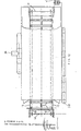
- the tubes can be transported in sets respectively of seven for tubes with a maximum diameter of 220 mm. and four for tubes of a diameter larger than 220 mm.; this is one of the main innovations of the transport system as it can be noticed from Fig. 14 and Fig. 16 which represent respectively the shape of the rollers and transversal bars of transport and advancing of the tubes in their exact half; the support system is arranged in such a way that the fixed support seats are seven so that with small diameter tubes on each support seat a tube will fit, whereas with larger diameter tubes a support will be left out using the intercalated supports and thus the set of transported tubes will be reduced to four, as it will be explained later on.
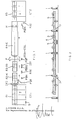
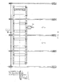
- the transferring and weighing bench is indicated with CT1, being the transfer carried out orthogonally to 'the loading line Rl, the data detecting electronic power station is indicated with CRD, the preheating tunnel is indicated with R2-H, the cleaning by means of surface brushing station is indicated with R3-SG, the painting station is indicated with P, the drying tunnel is indicated with R4-E, the marking station is indicated with M, the unloading line is indicated with R5 and the transversal transferring bench from the unloading line R5 is indicated with CT2.
- CT1 the transfer carried out orthogonally to 'the loading line Rl
- the data detecting electronic power station is indicated with CRD
- the preheating tunnel is indicated with R2-H
- the cleaning by means of surface brushing station is indicated with R3-SG
- the painting station is indicated with P
- the drying tunnel is indicated with R4-E
- the marking station is indicated with M
- the unloading line is indicated with R5
- the transversal transferring bench from the unloading line R5 is indicated
- PB1 manual control console CT1-R1 PBR weighing and length manual control console
- PBH manual control console R2-H PBH manual control console R2-H
- RB1 general relay set PBSG manual control console R3-SG
- CD1 moving manual control console PBP painting manual control console
- PBM marking station M manual control console PBM marking station M manual control console
- PB2 manual control console CT2-R5 and CGL general line control console PB1 manual control console CT1-R1
- units CT1 and CT2 are similarly structured, the only difference consisting in the presence at the inlet of CT1 of the respective weighing devices F.
- the plant control system is obviously supplied with a manual commutation which will prearrange the working cycle with four or seven tubes.
- the transfer bench CT1 is provided in the inlet with a set of platforms with standard weighing devices S commonly available on the market and therefore not represented, while the transfer system is carried out with a set of orthogonal chains 1 provided with seats to move either seven small tubes or four large tubes as above said.
- the set of chains 1 forming the chain conveyor CT1 is driven with a motor-reducer means operated by a central working panel system CGL and also by the manual control console PB1, being a chain supporting structure 1 through working wheels provided in an end operated by the motor-varying-reducer 2 step by step and regulated by the central system in accordance with the line advancing system and loading need.
- the loading line Rl is set up, which is constituted by a set of motorized rollers 3 driven by chains 4 by means of a motor-varying-reducer 5 and mounted on a frame 6 not connected with the transversal conveyor 1 and fit to be lifted and lowered by means of a fluid-dynamic cylinder system 7 in synchronous alternation with the arrival on the rollers 3 of the set of loading tubes in a number of four or seven in the precise corresponding position to the support and transfer seats of the rollers 3 forming the roller set of the loading system Rl.
- each roller 3 as represented in Figs. 14 and 15, is constituted by a tubular cylinder 8 with two supporting journals 9 welded at the ends for the relative rotation on the bearings and clutch of the connected wheel for motion transfer.
- the conveyor CT1 with the respective chains provided with seats perfectly corresponding to those of the supports 10 will rotate toward Rl only when Rl is lowered, to stop then on the roller set 3 waiting for the same roller plan Rl to be lifted for the tube removal, transferring them orthogonally along the treatment line R2-R5, according to the following explanations.
- the chain conveyor CT1 is provided'with an inlet position, a wait position and an outlet position.
- the chain conveyor CT1 will obviously be provided with a multiple cycle control which supplies the working sequences. The sequences provide to the tube transfer from the inlet and buffer positions to the conveyor R1.
- the conveyor control Rl is designed to work with a single motor and is provided with an automatic starting and stopping circuit.
- the line transfer rollers 3 are driven by said motor-reducers 5, continually working. But the motors can be manually operated and stopped by means of the respective buttons on the plant control consoles.
- roller position is variable in accordance with the advancing requirements prearranged for the same plant.
- the structure system is similar and symmetrical with an inverted working for the unloading station defined by the blade unit R5 and the orthogonal unloading chain conveyors CT2.
- roller system 3 is then repeated along the line also in stations R2-H and R3-SG.
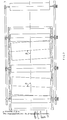
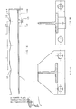
- Said transversal bars or blades 11 are essentially reverse "T" shaped and the upper edge presents grooves 12 corresponding to the tube receiving seat in Fig. 14, spaced apart of "i", exactly equal one another.
- the height of the roller plan is of about 1 m and the variable advancing speed is set to arrive till about 5 m/min., whereas the roller diameter for all the similar conveyors is 406 mm..
- the plant structure is provided with eighteen distributed rollers: eight rollers for Rl, five rollers for R2 and five rollers for R3, whereas for the remaining line portion starting from the painting station P said chain transfer with transversal support blades shaped as represented in Figs. 16, 17 and 18 and above described is provided.
- the conveying portion to the drying station R4 is provided with 62 blades with a blade spacing of 571 mm. and blade length of 2,240 mm., as for Rl and R3 rollers (R2 rollers are longer, due to the operating requirements of the preheating system, as will be later explained); each blade is supported by four bearings on the hinges 13 for the advancing chain of the type 1 1/2" as for the roller transmission chain.
- the conveyor R4 is also provided with a guide chain of 1 1/4".
- transfer prosecution is carried out in the conveyor R5 with four sets of nine blades each placed in each spacing sector between each orthogonal chain 1 of the plurality of unloading chains for the transfer and unloading of the tubes, thus being four independent chain sections stretched between the-respective motorized stretching and support wheels 14 (Figs. 11, 13).
- the conveyor R4 presents in the specific case a length of 17.4 m, whereas the drying station E presents a length of 14 m so that there will be a projection of the conveyor 4 of more than 3 m from the front to serve the painting station P as represented in Fig. 10 and for this purpose not represented for simplification but separately represented in a larger size in Figs. 8, 9.
- each chain conveyor chain moves on two wheels, one of which is driving and the other is loose and is supplied with a stretching device structured and placed according to well known shape and not represented.
- the sector R4 concerning the drying station includes a horizontal support guide beams respectively upper and lower lateral opposite 15 connected by orthogonal connection support structures 40 and the system of support chain couples 16 of the transversal bars 11 is provided with opposite sprocket devices 14, one of which is motor-driven by a respective motor-varying-reducer control 5 and the opposite one is supplied with stretching means not represented but of a common type.
- the chain portions with the relative transversal blades of the - .respective unloading station units -R5 for the alternate feeding of the transversal conveyor CT2 are vertically mounted on a movable structure by means of fluid dynamic cylinders 7 as for the loading system in order to transfer the tubes on the unloading orthogonal conveyor constituted by the unloading orthogonal chain set 1 realizing the structure CT2 (Figs. 11, 13).
- the conveyor set is checked by the control provided with a main contactor and the same conveyors can work only if this contactor is closed (not represented).
- Each control console includes an accessible emergency stop and two manually operated emergency stops are further provided for each fixed conveyor.
- the emergency stops are mounted on both sides of the conveyors (not represented); the pushing of an emergency stop will cause an immediate cutting out of the main contactor, cutting out all the motors and connecting all the brakes connected to the motor systems.
- the orthogonal conveyor will stop to successively receive an electric signal of next movement for transferring the next tube.
- the loading unit will supply an electric signal to CT1 to confirm that the motion has been completed, so that CT1 will advance of one or respectively two steps forward.
- CT1 will stop with the centre of the tube set exactly on the longitudinal line Rl and in this position the starting to the lifting of Rl will be carried out, to move the set of tubes along the treatment line from CT1 for then lowers again and allows the feeding station CT1 to carry on the transferring sequence of a new set of tubes.
- CT1 is supplied with control means for the manual operating through the pushbuttons PB1.
- CT2 starting position is placed on R5 and when a set of tubes transferred on R5 is stopped by the suitable predisposition of a presence indicator the lowering of R5 will be carried out with the support of the set of tubes on CT2, which will start the conveying toward the unloading unit (not represented) and obviously placed at CT2 end.
- CT2 will advance of one or two steps (according to the small or large diameter of the transported tubes) in order to place the next tube in the same unloading position.
- the preheating station R2-H includes a portion R2 of the above described roller conveyor and a tunnel H sorrounding said portion, for treating the tubes T while these ones advance in this portion R2 through the tunnel (Figs. 1, 4, 5).
- the unit is planned for preheating the tubes by means of a front preheating section and a back conditioning section.
- the front preheating section includes a plurality of burners, in the specific case gas burners, arranged in transversal rows respectively under and over the advancing line of the tubes 17.
- the same burners are supported by means of transversal support beams on the rollers 3 of the conveyor and under the rollers 3 of the same conveyor R2 in such a way to hit with the flame respectively the lower and the upper part of the tubes.
- the burners 17 are placed inclined and revolving for an optimum position of the tube treatment and the upper rows are vertically movable.
- the tunnel H is constructed with selfsupporting modular portions riveted together.
- the walls and roof of the preheating station are insulated in order to reduce to a minimum the loss of heat for the difference of the outside temperature.
- the inside parts and the roof of the unit are realized in heat resistant, refractory stainless steel.
- the supports for each roller of the conveyor system R2 and the relative chain transmission are placed on the outside of the unit in order to avoid problems with the lubrificants deriving from the high temperature and for this reason the rollers are obviously longer than the other ones of the transferring system.
- an aspirator 18 for fuel-gas is provided, whose piping 19 is meant to carry the waste-heat to the next drying station R4-E for a higher efficiency of the plant.
- the aspirator for fuel-gas 18 will be of the non-sparking type and will _be operated by the control unit in connection with the detector CRD.
- the burn-in system of the burners will be connected after the aspirator has worked the necessary time to ensure the effective cleaning of the tunnel, and the burners can light only when the aspirator works, while the same burners will immediately blow out if the aspirator stops.
- a drying or ventilation or conditioning section Downstream the burner section 17 a drying or ventilation or conditioning section is placed, which is provided with fans 38 for the forced ventilation of the tubes by means of blower ramps (not represented but of a well known type) placed over.and under the advancing tubes, thus ensuring an effective drying of the same tubes.
- the drying fans after being connected, will work only when the tubes are conveyed through the drying section as for the burners.
- the fans will be obviously automatically operated and stopped, after the burners are respectively lighted and blown out.
- the discontinous working of the drying fans will reduce to a minimum the loss of heat.
- control panels PBH and RB1 placed near the station R2-H are meant for this purpose for the relative working near the same unit.
- the unit includes a common main contactor with a circuit switch, with complete protection of each motor.
- Sensors are provided to set out the flow of the tubes and these sensors are placed on the conveyor, at the inlet of the tubes, and cover the entire width of a set of tubes, but record also a single tube.
- the burner width selection switch can be set in various positions in which a burner width is provided mainly to fit standard set of small diameter tubes or for burner width fit for treating large diameter tubes.
- a selector of heat delivery is further provided, which regulates the increase of the temperature required for the tubes, with different transport speed, according to the tubes to be treated.
- the selector of heat delivery makes the regular emission of heat possible step by step between about 10% and 100% of the maximum delivery.
- the selection switch will preferably have six trips when the plant is provided with three rows of burners and four trips when it is provided with two rows of burners.
- the unit will be further supplied with a safety thermostat for protection against overheating and this in such a way that these burners are disconnected if the thermostat trips for the overheating, simultaneously switching on a pilot lamp, placed on the control panel, which shows the too high temperature:
- the burners will obviously be provided with ignition electrodes and checking unit of the same ignition.
- the ignition elettrode of each row of burners will receive current by means of a high-voltage transformer, at the same time, opening a solenoid valve, gas will be distributed after receiving an ignition signal.
- the function of the extension electrode is obviously to switch off immediately after the ignition checking unit records the presence of the flame.
- the ignition checking unit.might not record the presence of the flame after gas has been emitted for an adequate time, or during the heating process.
- the gas supply will thus be automatically interrupted, and a red alarm lamp will be provided for this purpose in the control panel which lighting up will show the irregular working.
- the manual working can be operated on the same control panel in order to facilitate the operating checking and the possible recordings.
- the brushing and blowing unit R3-SG includes the roller transport system R3 and the tunnel of the treatment of the tubes or the actual brushing SG.
- the tunnel is further supplied with a blowing system (not represented) of a well-known type for the removal of the residual dust and the blowing will be carried out with blasts of compressed air in order to avoid the dust outlet from the same tunnel.
- a blowing system (not represented) of a well-known type for the removal of the residual dust and the blowing will be carried out with blasts of compressed air in order to avoid the dust outlet from the same tunnel.
- the blowing system will be realized with nozzles placed over and under the transfer line transversally to the advancing direction of the tubes.
- An electro-pneumatic valve will operate the air inflow to the nozzles when the brushes work, a delay breaker connected in line with the electro-valve control will allow the delayed closure of' the comppessed air when the operating of the brushes 7 stops.
- the dust removal will be effected by means of a suitable centrifugal fan of a well-known tecnique, placed downstream a filter, as for example the filter F in Fig. 20, or any other of a suitable type.
- the air change system must ensure a change of at least 100 times the volume of. the tunnel chamber per hour, in order to maintain a suitable vacuum degree inside the tunnel to avoid the possible dust transfer in the outside sorrounding environment.
- the brushes will preferably have a diameter of about 1,200 mm. and will preferably operate at 150 r.p.m. and the same brushes will be overhung on systems of spring cushioning of the bucket type or any other suitable type, while the lifting will be carried out by means of motor-reducers.
- console PBSG-CB1 is provided as above described.
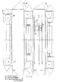
- the painting station P includes two painting cabins P1, P2, as represented in Figs. 8 and 9 which provide upstream in connection with the preceding conveyor R3 an electronic detectingastation of the tubes to be painted 24 fit to operate the complete painting unit.
- the painting cabins Pl, P2 include respectively: the first one a couple of upper guides 25 for an upper translation trolley in a transversal alternate movement 26 supporting a plurality of painting means 27, the second one a couple of lower guides 28 for a lower support trolley 29 supporting a plurality of under painting upward oriented means 30, placed under the tube treatment line.
- the two cabins Pl and P2 are separate and independent and are further supplied with over and under opposite rotating filters respectively 31, 32, 33 and 34 to allow a suitable air change and to maintain the painting environment clean.
- the system is structured for a translation speed in accordance with the treatment line equal to a maximum of 5 m/min. and with this maximum translation speed a painting with a 15% of dry tubes can be carried out covering a smooth or horizontal surface with a 25 micron thickness film carrying out the spraying with one coat.
- the paint supply system will preferably be of Airless type but does not obviously exclude electrostatic systems, in this specific case eight sprayers are provided and the painting pumps are two, with two high pressure types, while the sprayers speed is of about 1.5 m/sec..
- the ventilation is carried out with two aspirators of a suitable power flow to ensure an air change of about 500 t./hr.; on the floor a water trickle washing .:ill be preferably provided for recovery of the paint not utilized in the cabin (not represented but of a well-known type).
- Each painting unit can paint in two ways, with an alternate forward and backward movement over and under the advancing tubes so that the painting will be carried out both going and returning.
- the automatic control of the plant will ensure an even,spraying, applying an even painting thickness reducing to a minimum the paint waste.
- the spraying means are of an interchangeable type and are supplied completely set up and cabled reducing to a minimum the setting up times.
- Each support trolley, respectively 26, 29, runs over three support points in the respective guide couples by means of connection and sliding rollers 41, 42 and 43.
- Each sliding system consists of a couple of rollers so that a roller goes on the upper side of the motion path and a roller goes on the lower part of the same path.
- the motion paths are covered for their entire length so as to protect them from the painting together with the rollers and are placed-outside the cabins.
- the coverings will be easily removable.
- the painting trolleys respectively 26, 29 are operated by a common motor-reducer and chain transmission (not represented but of a well-known technique), and similarly supports for cables and tubes for the painting trolleys are provided, by means oT two track systems, one for the upper trolley and the other for the lower trolley.
- the distance of the sprayers from the tubes is programmed through the control central unit particularly for the upper sprayers which are operated at a varying height according to the tube diameter.
- the upper sprayers are always positioned at the ideal distance from the upper surface of the tubes as they will obviously automatically lifted and lowered according to the height of the tubes passing through the cabin.
- a fluidoildynamic cylinder 44 of a well-known technique, is provided, operated by outside pushbuttons in the respective control consoles so as to ensure that the distance between the top surface of the tubes to be treated and the spraying means is always the optimum.
- a pointer will be further provided to visually represent the position of the spraying means with reference to the tubes.
- a safety system will prevent the plant working if the distance between the top surface of the tubes to be treated and the sprayers is not the right one.
- the sprayers are placed in sets of two as represented in Fig. 8 and each will be set up at a corner of 90° as regards the other and at 45° as regards the direction of translation.
- both the sprayers of a set will work alternatively according to the direction of translation of the painting trolleys.
- the oblique position of the sprayers will ensure that the tube is painted on the oblique and vertical surfaces with the most suitable angle.
- the opening and closing positions of the sprayers will be changed according to the width of the tubes, that is according to the type of the advancing tubes and their number.
- the spraying structure in this particular case Airless, will be supplied with all the necessary means for the relative working as the high pressure pump, the recirculation system on the suction side of the pump, filtering systems and relative delivery systems.
- Each cabin is constituted by independent modular units and is inside provided with fluorescence lignting means (P1, P2).
- the supporting structure is mainly realized in metallic structurals welded and bolted together with a rigid frame which supports the motion paths for the painting trolleys.
- Each cabin is provided with an aspirator of suitable characteristics and section placed near the same cabin.
- the two support systems of cables and tubes to the painting trolleys are contained, for their length, in housings inside the same painting cabin.
- each cabin is smooth and without inward jutting out components to avoid paint obstructions.
- the aspirators will be of a non-sparking type, set up in a separate cabinet placed at one end of the painting cabin to convey through a suction pipe 35 the air containing the paint to the waste- and/or regeneration.
- Every aspirator will work continually and the painting spray can be carried out only if every aspirator works, whereas if the aspirator, for any reason, should stop while working, the spraying must immediately stop.
- Each cabin supports, as above described, two dry filtering systems with rotating filters with winding off coil at one side and winding coil at the other 36, 37 or vice versa, the coils being easily accessible from the outside for their replacement.
- the starting of the filtering carpets will be automatic and regulated by differential pressostats.
- Every single painting delivery will be automatically controlled according to the advancing tubes and the transport speed (trolley translation).
- the advancing speed of the tubes will be recorded by means of a pulse generator (not represented but of a well-known type) which transmits a pulse to the control system every time a set of tubes moves according to a predetermined measure.
- a pulse generator not represented but of a well-known type
- the pulse generator is switched on and off according 0080978 feed of the tubes by means of an electric sensor placed just in front of the painting cabin.
- the start and stop, as also the regulation of the automatic spraying , are carried out by the control console preferably of a transistorized type placed near the cabin PBP as above described.
- the control is delayed for the opening and closing of the sprayers according to the 45° angle by the blast of paint as regards the tubes and the delays for the opening and closing of the sprayers can be regulated independently from the control and working panel.
- the control and working panel further includes a main contactor of the spraying unit and emergency stop.
- the unit can work only if the main contactor is closed.
- the unit control system will trace the feed of the tubes and automatically control the working according to the flow through the cabin.
- the system starts for the first paint delivery and settles when the painting of the tubes is finished.
- the automatic working of the painting station is the following:
- the drying station R4-E is structured as represented in Figs. 10, 12 and consists essentially of the drying cabin E, with the enclosed conveyor R4 above described.
- the cabin is of a tunnel type with closing walls according to well-known technique and the drying air recovered from the preheating tunnel 19 is conveyed to it and further a suction system 39 is provided by means of a couple of aspirators not represented but of a well-known technique.
- a marking unit M is provided, of a commonly available type, as for example the marker produced by Magnemag, Metervuen 18, COPENAGHEN.
Landscapes
- Application Of Or Painting With Fluid Materials (AREA)
- Coating Apparatus (AREA)
- Chemical Treatment Of Metals (AREA)
- Drying Of Solid Materials (AREA)
- Heat Treatment Of Articles (AREA)
Priority Applications (1)
| Application Number | Priority Date | Filing Date | Title |
|---|---|---|---|
| AT82830247T ATE32568T1 (de) | 1981-11-27 | 1982-10-04 | Standardisierte anlage fuer die oberflaechenbehandlung von metallrohren durch vorheizen, reinigen, lackieren, trocknen und markieren. |
Applications Claiming Priority (2)
| Application Number | Priority Date | Filing Date | Title |
|---|---|---|---|
| IT8350181 | 1981-11-27 | ||
| IT83501/81A IT1147191B (it) | 1981-11-27 | 1981-11-27 | Impianto in linea standard per il trattamento superficiale di preriscaldo, spazzolatura, verniciatura, essiccaggio e marcatura di tubi metallici |
Publications (3)
| Publication Number | Publication Date |
|---|---|
| EP0080978A2 true EP0080978A2 (de) | 1983-06-08 |
| EP0080978A3 EP0080978A3 (en) | 1985-03-06 |
| EP0080978B1 EP0080978B1 (de) | 1988-02-24 |
Family
ID=11322642
Family Applications (1)
| Application Number | Title | Priority Date | Filing Date |
|---|---|---|---|
| EP82830247A Expired EP0080978B1 (de) | 1981-11-27 | 1982-10-04 | Standardisierte Anlage für die Oberflächenbehandlung von Metallrohren durch Vorheizen, Reinigen, Lackieren, Trocknen und Markieren |
Country Status (4)
| Country | Link |
|---|---|
| EP (1) | EP0080978B1 (de) |
| AT (1) | ATE32568T1 (de) |
| DE (1) | DE3278131D1 (de) |
| IT (1) | IT1147191B (de) |
Cited By (22)
| Publication number | Priority date | Publication date | Assignee | Title |
|---|---|---|---|---|
| ITVI20100256A1 (it) * | 2010-09-21 | 2012-03-22 | Comital S A S Di Giacomello Ivana & C | Impianto per la decorazione di oggetti allungati |
| US8545817B2 (en) | 2006-08-04 | 2013-10-01 | L'oreal | Cosmetic composition comprising at least one polysaccharide of λ-carrageenan type in aerosol form, method for the cosmetic treatment of keratinous fibers, and product comprising the composition |
| CN107282551A (zh) * | 2017-07-20 | 2017-10-24 | 禹州市新光铸造有限公司 | 一种用于毛坯管材的自动清洗喷漆装置 |
| CN107309130A (zh) * | 2017-08-24 | 2017-11-03 | 太仓市众翔精密五金有限公司 | 一种控制漆膜厚度的高效自动喷漆线及其工艺 |
| CN108126875A (zh) * | 2018-01-25 | 2018-06-08 | 长春市漫思教育科技有限公司 | 一种3d打印零件表面处理装置及方法 |
| CN109107813A (zh) * | 2018-11-15 | 2019-01-01 | 上海烨恒木业机械有限公司 | 一种基于喷涂及辊涂的一体机系统 |
| CN109482410A (zh) * | 2019-01-16 | 2019-03-19 | 泉州市海恩德机电科技发展有限公司 | 一种喷漆生产线 |
| CN110170410A (zh) * | 2019-04-29 | 2019-08-27 | 青岛市首胜实业有限公司 | 一种橱柜板材双面喷漆干燥系统 |
| CN110715581A (zh) * | 2019-10-24 | 2020-01-21 | 湖南军成科技有限公司 | 一种大弹生产线 |
| CN112403720A (zh) * | 2020-10-30 | 2021-02-26 | 郭玉红 | 一种适用于隧道开挖断面辅助划线设备 |
| CN112547391A (zh) * | 2020-11-17 | 2021-03-26 | 国佳新材湖北环保凝胶产业园有限公司 | 一种高效率气凝胶卷材的涂布复合装备 |
| CN112756150A (zh) * | 2020-12-31 | 2021-05-07 | 太仓市欧士达金属制品有限公司 | 一种五金零件产品用防锈漆喷涂装置 |
| CN113499962A (zh) * | 2021-06-21 | 2021-10-15 | 阎慧贞 | 一种高端装备制造用金属管表面防锈涂抹设备 |
| CN113786947A (zh) * | 2021-09-24 | 2021-12-14 | 江西金屹有色金属有限公司 | 一种生产加工用铜线上色设备 |
| CN113996459A (zh) * | 2020-10-30 | 2022-02-01 | 中冶天工集团有限公司 | 一种防护用脚手管标准化制作装置及使用方法 |
| CN114345609A (zh) * | 2021-12-30 | 2022-04-15 | 迅展机械(无锡)有限公司 | 一种自动喷蜡装置 |
| CN114589075A (zh) * | 2022-01-20 | 2022-06-07 | 杭州吉众机电股份有限公司 | 一种产品表面喷涂处理工艺 |
| CN114832991A (zh) * | 2022-05-24 | 2022-08-02 | 大连理工大学 | 一种用于缠绕式换热管束喷涂催化剂的系统 |
| CN114887796A (zh) * | 2022-05-13 | 2022-08-12 | 无锡市新达共创纳米科技有限公司 | 一种活塞杆表面陶瓷涂层喷涂加工工艺 |
| CN115106237A (zh) * | 2022-08-10 | 2022-09-27 | 山东唐口煤业有限公司 | 一种井下无缝钢管全自动除锈喷漆一体设备 |
| CN116833012A (zh) * | 2023-03-24 | 2023-10-03 | 盐城现山设备科技有限公司 | 一种汽车部件自动喷涂、检测设备 |
| CN119771658A (zh) * | 2025-03-11 | 2025-04-08 | 连云港德耀机械科技有限公司 | 一种钢材生产加工用输送导离装置 |
Family Cites Families (4)
| Publication number | Priority date | Publication date | Assignee | Title |
|---|---|---|---|---|
| US2794448A (en) * | 1949-04-09 | 1957-06-04 | Columbia Cable & Electric Corp | Art of spray coating of tubes |
| US3134476A (en) * | 1962-03-28 | 1964-05-26 | Miner Machine Company | Corner transfer unit for conveyor systems |
| US4096300A (en) * | 1976-05-24 | 1978-06-20 | William Virgil R | Process of coating a series of metal members |
| US4173198A (en) * | 1977-11-25 | 1979-11-06 | The B. F. Goodrich Company | Tread end cementer |
-
1981
- 1981-11-27 IT IT83501/81A patent/IT1147191B/it active
-
1982
- 1982-10-04 AT AT82830247T patent/ATE32568T1/de not_active IP Right Cessation
- 1982-10-04 EP EP82830247A patent/EP0080978B1/de not_active Expired
- 1982-10-04 DE DE8282830247T patent/DE3278131D1/de not_active Expired
Cited By (30)
| Publication number | Priority date | Publication date | Assignee | Title |
|---|---|---|---|---|
| US8545817B2 (en) | 2006-08-04 | 2013-10-01 | L'oreal | Cosmetic composition comprising at least one polysaccharide of λ-carrageenan type in aerosol form, method for the cosmetic treatment of keratinous fibers, and product comprising the composition |
| WO2012038896A1 (en) * | 2010-09-21 | 2012-03-29 | Comital S.A.S. Di Giacomello Ivana & C. | Method and plant for surface decoration of elongate items |
| US9415402B2 (en) | 2010-09-21 | 2016-08-16 | Comital S.A.S. Di Giacomello Ivana E C. | Method and plant for surface decoration of elongate items |
| ITVI20100256A1 (it) * | 2010-09-21 | 2012-03-22 | Comital S A S Di Giacomello Ivana & C | Impianto per la decorazione di oggetti allungati |
| CN107282551A (zh) * | 2017-07-20 | 2017-10-24 | 禹州市新光铸造有限公司 | 一种用于毛坯管材的自动清洗喷漆装置 |
| CN107309130B (zh) * | 2017-08-24 | 2023-04-07 | 太仓市众翔精密五金有限公司 | 一种控制漆膜厚度的高效自动喷漆线及其工艺 |
| CN107309130A (zh) * | 2017-08-24 | 2017-11-03 | 太仓市众翔精密五金有限公司 | 一种控制漆膜厚度的高效自动喷漆线及其工艺 |
| CN108126875A (zh) * | 2018-01-25 | 2018-06-08 | 长春市漫思教育科技有限公司 | 一种3d打印零件表面处理装置及方法 |
| CN109107813A (zh) * | 2018-11-15 | 2019-01-01 | 上海烨恒木业机械有限公司 | 一种基于喷涂及辊涂的一体机系统 |
| CN109482410A (zh) * | 2019-01-16 | 2019-03-19 | 泉州市海恩德机电科技发展有限公司 | 一种喷漆生产线 |
| CN109482410B (zh) * | 2019-01-16 | 2024-04-05 | 泉州市海恩德机电科技发展有限公司 | 一种喷漆生产线 |
| CN110170410A (zh) * | 2019-04-29 | 2019-08-27 | 青岛市首胜实业有限公司 | 一种橱柜板材双面喷漆干燥系统 |
| CN110715581A (zh) * | 2019-10-24 | 2020-01-21 | 湖南军成科技有限公司 | 一种大弹生产线 |
| CN112403720B (zh) * | 2020-10-30 | 2021-07-16 | 李寿莹 | 一种适用于隧道开挖断面辅助划线设备 |
| CN113996459A (zh) * | 2020-10-30 | 2022-02-01 | 中冶天工集团有限公司 | 一种防护用脚手管标准化制作装置及使用方法 |
| CN112403720A (zh) * | 2020-10-30 | 2021-02-26 | 郭玉红 | 一种适用于隧道开挖断面辅助划线设备 |
| CN112547391A (zh) * | 2020-11-17 | 2021-03-26 | 国佳新材湖北环保凝胶产业园有限公司 | 一种高效率气凝胶卷材的涂布复合装备 |
| CN112547391B (zh) * | 2020-11-17 | 2021-08-06 | 中凝科技(湖北)有限公司 | 一种高效率气凝胶卷材的涂布复合装备 |
| CN112756150A (zh) * | 2020-12-31 | 2021-05-07 | 太仓市欧士达金属制品有限公司 | 一种五金零件产品用防锈漆喷涂装置 |
| CN113499962A (zh) * | 2021-06-21 | 2021-10-15 | 阎慧贞 | 一种高端装备制造用金属管表面防锈涂抹设备 |
| CN113786947A (zh) * | 2021-09-24 | 2021-12-14 | 江西金屹有色金属有限公司 | 一种生产加工用铜线上色设备 |
| CN114345609A (zh) * | 2021-12-30 | 2022-04-15 | 迅展机械(无锡)有限公司 | 一种自动喷蜡装置 |
| CN114589075B (zh) * | 2022-01-20 | 2023-10-03 | 杭州吉众机电股份有限公司 | 一种产品表面喷涂处理工艺 |
| CN114589075A (zh) * | 2022-01-20 | 2022-06-07 | 杭州吉众机电股份有限公司 | 一种产品表面喷涂处理工艺 |
| CN114887796A (zh) * | 2022-05-13 | 2022-08-12 | 无锡市新达共创纳米科技有限公司 | 一种活塞杆表面陶瓷涂层喷涂加工工艺 |
| CN114887796B (zh) * | 2022-05-13 | 2023-11-24 | 无锡市新达共创纳米科技有限公司 | 一种活塞杆表面陶瓷涂层喷涂加工工艺 |
| CN114832991A (zh) * | 2022-05-24 | 2022-08-02 | 大连理工大学 | 一种用于缠绕式换热管束喷涂催化剂的系统 |
| CN115106237A (zh) * | 2022-08-10 | 2022-09-27 | 山东唐口煤业有限公司 | 一种井下无缝钢管全自动除锈喷漆一体设备 |
| CN116833012A (zh) * | 2023-03-24 | 2023-10-03 | 盐城现山设备科技有限公司 | 一种汽车部件自动喷涂、检测设备 |
| CN119771658A (zh) * | 2025-03-11 | 2025-04-08 | 连云港德耀机械科技有限公司 | 一种钢材生产加工用输送导离装置 |
Also Published As
| Publication number | Publication date |
|---|---|
| IT8183501A0 (it) | 1981-11-27 |
| EP0080978A3 (en) | 1985-03-06 |
| IT1147191B (it) | 1986-11-19 |
| EP0080978B1 (de) | 1988-02-24 |
| DE3278131D1 (en) | 1988-03-31 |
| ATE32568T1 (de) | 1988-03-15 |
Similar Documents
| Publication | Publication Date | Title |
|---|---|---|
| EP0080978B1 (de) | Standardisierte Anlage für die Oberflächenbehandlung von Metallrohren durch Vorheizen, Reinigen, Lackieren, Trocknen und Markieren | |
| US4096300A (en) | Process of coating a series of metal members | |
| CN101065630B (zh) | 干燥间 | |
| US4926746A (en) | Work chamber with shifting ventilation zone | |
| US20120094031A1 (en) | Method and coating plant for providing a workpiece with a coating | |
| CA1052672A (en) | Plant for surface treating, in particular pickling and phosphatizing, metallic work pieces | |
| US7815036B2 (en) | Modular manufacturing chain including a position tracking device and method of operation therefor | |
| CN102209594B (zh) | 用于对物品进行表面处理的设备 | |
| RU2465948C2 (ru) | Фильтр рукавный для трехступенчатой очистки воздуха от механических примесей | |
| US7900767B2 (en) | Modular manufacturing chain including a vertical lift device and method of operation thereof | |
| EP0537869A2 (de) | Bodenflächenstrahlgerät | |
| CN105327826A (zh) | 一种地板长边边缘倒角涂漆设备 | |
| RU2437711C1 (ru) | Фильтр рукавный для трехступенчатой очистки воздуха от механических примесей | |
| US4587927A (en) | Painting- and evaporation cabin with air-return ventilation | |
| CN112705395B (zh) | 一种钣金件喷涂系统 | |
| EP0055536B1 (de) | Vorrichtung zur elektrostatischen Beschichtung länglicher Körper | |
| CN115106237A (zh) | 一种井下无缝钢管全自动除锈喷漆一体设备 | |
| KR100817486B1 (ko) | 피혁자동도장장치의 컨베이어시스템 | |
| CN113966253B (zh) | 用于向大体平坦的部件施用涂料的设备 | |
| CN206791506U (zh) | 颗粒物料电磁加热连续烘焙炒制机 | |
| CN112589683B (zh) | 轨道交通铁路货车车门表面预处理方法 | |
| US4214972A (en) | Sheet handling apparatus | |
| CN217393139U (zh) | 一种工业用电气自动化喷淋设备 | |
| CN219816793U (zh) | 仿古石材的生产系统 | |
| JP2538315B2 (ja) | 移動体清掃設備 |
Legal Events
| Date | Code | Title | Description |
|---|---|---|---|
| PUAI | Public reference made under article 153(3) epc to a published international application that has entered the european phase |
Free format text: ORIGINAL CODE: 0009012 |
|
| AK | Designated contracting states |
Designated state(s): AT BE CH DE FR GB LI LU NL SE |
|
| PUAL | Search report despatched |
Free format text: ORIGINAL CODE: 0009013 |
|
| AK | Designated contracting states |
Designated state(s): AT BE CH DE FR GB LI LU NL SE |
|
| 17P | Request for examination filed |
Effective date: 19850507 |
|
| 17Q | First examination report despatched |
Effective date: 19860217 |
|
| R17C | First examination report despatched (corrected) |
Effective date: 19860613 |
|
| GRAA | (expected) grant |
Free format text: ORIGINAL CODE: 0009210 |
|
| AK | Designated contracting states |
Kind code of ref document: B1 Designated state(s): AT BE CH DE FR GB LI LU NL SE |
|
| PG25 | Lapsed in a contracting state [announced via postgrant information from national office to epo] |
Ref country code: NL Effective date: 19880224 Ref country code: LI Effective date: 19880224 Ref country code: FR Free format text: THE PATENT HAS BEEN ANNULLED BY A DECISION OF A NATIONAL AUTHORITY Effective date: 19880224 Ref country code: CH Effective date: 19880224 Ref country code: BE Effective date: 19880224 Ref country code: AT Effective date: 19880224 |
|
| REF | Corresponds to: |
Ref document number: 32568 Country of ref document: AT Date of ref document: 19880315 Kind code of ref document: T |
|
| PG25 | Lapsed in a contracting state [announced via postgrant information from national office to epo] |
Ref country code: SE Effective date: 19880229 |
|
| REF | Corresponds to: |
Ref document number: 3278131 Country of ref document: DE Date of ref document: 19880331 |
|
| REG | Reference to a national code |
Ref country code: CH Ref legal event code: PL |
|
| EN | Fr: translation not filed | ||
| NLV1 | Nl: lapsed or annulled due to failure to fulfill the requirements of art. 29p and 29m of the patents act | ||
| PG25 | Lapsed in a contracting state [announced via postgrant information from national office to epo] |
Ref country code: GB Effective date: 19881004 |
|
| PG25 | Lapsed in a contracting state [announced via postgrant information from national office to epo] |
Ref country code: LU Free format text: LAPSE BECAUSE OF NON-PAYMENT OF DUE FEES Effective date: 19881031 |
|
| PLBE | No opposition filed within time limit |
Free format text: ORIGINAL CODE: 0009261 |
|
| STAA | Information on the status of an ep patent application or granted ep patent |
Free format text: STATUS: NO OPPOSITION FILED WITHIN TIME LIMIT |
|
| 26N | No opposition filed | ||
| PG25 | Lapsed in a contracting state [announced via postgrant information from national office to epo] |
Ref country code: DE Effective date: 19890701 |
|
| GBPC | Gb: european patent ceased through non-payment of renewal fee |