EP0080991A2 - Lautsprecher - Google Patents
Lautsprecher Download PDFInfo
- Publication number
- EP0080991A2 EP0080991A2 EP82850242A EP82850242A EP0080991A2 EP 0080991 A2 EP0080991 A2 EP 0080991A2 EP 82850242 A EP82850242 A EP 82850242A EP 82850242 A EP82850242 A EP 82850242A EP 0080991 A2 EP0080991 A2 EP 0080991A2
- Authority
- EP
- European Patent Office
- Prior art keywords
- loudspeaker
- wall
- casing
- horn
- sound
- Prior art date
- Legal status (The legal status is an assumption and is not a legal conclusion. Google has not performed a legal analysis and makes no representation as to the accuracy of the status listed.)
- Granted
Links
Images


Classifications
-
- H—ELECTRICITY
- H04—ELECTRIC COMMUNICATION TECHNIQUE
- H04R—LOUDSPEAKERS, MICROPHONES, GRAMOPHONE PICK-UPS OR LIKE ACOUSTIC ELECTROMECHANICAL TRANSDUCERS; ELECTRIC HEARING AIDS; PUBLIC ADDRESS SYSTEMS
- H04R5/00—Stereophonic arrangements
- H04R5/02—Spatial or constructional arrangements of loudspeakers
-
- H—ELECTRICITY
- H04—ELECTRIC COMMUNICATION TECHNIQUE
- H04R—LOUDSPEAKERS, MICROPHONES, GRAMOPHONE PICK-UPS OR LIKE ACOUSTIC ELECTROMECHANICAL TRANSDUCERS; ELECTRIC HEARING AIDS; PUBLIC ADDRESS SYSTEMS
- H04R1/00—Details of transducers, loudspeakers or microphones
- H04R1/20—Arrangements for obtaining desired frequency or directional characteristics
- H04R1/22—Arrangements for obtaining desired frequency or directional characteristics for obtaining desired frequency characteristic only
- H04R1/26—Spatial arrangements of separate transducers responsive to two or more frequency ranges
-
- H—ELECTRICITY
- H04—ELECTRIC COMMUNICATION TECHNIQUE
- H04R—LOUDSPEAKERS, MICROPHONES, GRAMOPHONE PICK-UPS OR LIKE ACOUSTIC ELECTROMECHANICAL TRANSDUCERS; ELECTRIC HEARING AIDS; PUBLIC ADDRESS SYSTEMS
- H04R1/00—Details of transducers, loudspeakers or microphones
- H04R1/20—Arrangements for obtaining desired frequency or directional characteristics
- H04R1/32—Arrangements for obtaining desired frequency or directional characteristics for obtaining desired directional characteristic only
- H04R1/323—Arrangements for obtaining desired frequency or directional characteristics for obtaining desired directional characteristic only for loudspeakers
Definitions
- This invention relates to loudspeakers for high-quality stereophonic loudspeaker systems intended to be positioned on the floor close to a wall of a room.
- the quality of reproduction which a loudspeaker of this type can provide in a room is known to be influenced by the loudspeaker's interaction with adjacent reflecting boundary surfaces in the room, and especially by the reflected sound from the wall behind the loudspeaker and from the floor.
- the reflected sound increases the efficiency of the loudspeaker.
- the phase angle between direct and reflected sound is greater than about 120 degrees, i. e. when the distance travelled by the reflected sound exceeds that of the direct sound by more than one third of a wave-length, the resulting sound as a function of frequency will alternate between minima and maxima.
- the reflected sound from the wall and from the floor distorts not only the amplitude response in the frequency domain but also the amplitude response in the time domain.
- a loudspeaker for stereophonic loudspeaker systems comprising a casing having a frontal wall, a side wall, a top wall, a substantially vertical rear wall and a substantially horizontal bottom wall, a first number of loudspeaker units arranged in the casing for radiating the lower frequency ranges, at least one of said first number of loudspeaker units being located near one or both of said rear and bottom walls, and a second number of loudspeaker units arranged near the rearmost part of the said top wall for radiating the higher frequency ranges and oriented so as to have its axis of radiation or their axes of radiation directed slantwise forwards to intersect an imaginary plane flush with said side wall, said loudspeaker being characterized in that said first number of loudspeaker units is arranged to be the sound source for at least the frequency range from 50 to 800 Hz and to have its outlet or outlets for frequencies above 50 Hz located at one or both of said frontal and side walls, at least one of said first number of loudspeaker units is arranged to
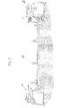
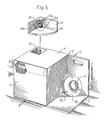
- the different embodiments of the loudspeaker shown in Figs. 1, 3, 4 and 5 have a casing with a frontal wall 1, a side wall 2, a top wall 4, a rear wall 5 and a bottom wall 6.
- They are the left-hand loudspeakers of a mirror-image pair of stereophonic loudspeakers such as the left-hand loudspeaker 22 and the right-hand loudspeaker 23 shown in Fig. 2 and are intended to be placed with the bottom walls 6 against the floor, preferably with a thick carpet or felt as a spacer, and with the rear walls 5 close to and virtually flush with a wall 25 of a room.
- a loudspeaker unit 7 or a group of loudspeaker units, of which the two units 7a and 7b are visible from the outside, is arranged in the side wall 2 so as to co- operate with a large part of the internal volume of the casing and with a ducted port 8, and so as to be the sound source for the low frequencies up to between 150 and 250 Hz or up to between 200 and 300 Hz, respectively.
- the ducted port 8 is arranged to be a sound radiating surface below 50 Hz.
- Higher frequencies up to between 800 and 1000 Hz are radiated by a loudspeaker unit 9 or 9a, respectively, arranged to co-operate with a smaller part of the internal volume of the casing and mounted close to a vertical casing structure wall which protrudes so as to restrict the rearward radiation of the loudspeaker.
- the rear wall 5 and the bottom wall 6 of the casing extend past the side wall 2 so as to form with the side wall 2 a short conical horn with a solid angle of n/2 steradians.
- the side wall 2 has a triangular outwardly inclined portion 3 with an opening receiving the loudspeaker unit 9 mounted as close as possible to the three walls 2, 5 and 6 of said horn, said unit 9 having its back and its magnet structure 11 facing outwards.
- a mounting collar 10 increases the efficiency of the loudspeaker unit 9 in the frequency range 400-1000 Hz, and a moderating layer of sound absorbing material, e.g. soft felt, is provided below and around the mounting collar 10 (but not shown).
- the loudspeaker unit 9a is arranged at the smaller end of a horn-type passage having its mouth in the frontal wall 1.
- a separate, e.g. semi-cylindrical member 27 has a similar acoustic function as the mounting collar 10 above, and it is also provided with soft felt (not shown).
- a wall member 26 holding said group of loudspeaker units for the low frequencies is replaced by another wall member of the same size which holds a single loudspeaker mechanism in the same position as the loudspeaker unit 7b.
- the rear wall 5 and the bottom wall 6 extend from 0.1 to 0.3 m past the side wall 2.
- Two loudspeaker units 79a and 79b or a single loudspeaker unit 79 is or are mounted close to the bottom wall 6 and arranged so as to cooperate with the internal volume of the casing (in the embodiment shown in Fig. 5 cooperating with a ducted port 8), and so as to be the sound source for low and mid-range frequencies up to between 800 and 1000 Hz or up to between 800 and 1500 Hz, respectively.
- the loudspeaker unit 79a is mounted in the frontal wall 1 and at a substantial preferably maximum distance from the side wall 2, whilst the loudspeaker unit 79b is mounted in the side wall 2 and close to the rear wall 5.
- the side wall 2 has an outwardly inclined portion 3 in which the loudspeaker unit 79 is mounted as described above in connection with the loudspeaker unit 9 of the embodiment shown in Fig. 1.
- the inclined portion 3 forms an angle of between 30 and 60 degrees with respect to the rest of the said side wall and between 45 and 90 degrees with respect to the said rear wall and with respect to the said bottom wall of the casing.
- a loudspeaker unit 79 with an outside diameter of 0.18 m has a frequency range extending to about 1500 Hz.
- a loudspeaker unit 12 with a dome-shaped diaphragm 13 is arranged to radiate the frequency range from between 800 or 1000 Hz and up to between 3 and 5 kHz.
- the diaphragm 13 is arranged to cooperate with a horn-type structure comprising a lower reflector surface 16 and two side reflector surfaces 17 and 18 or 18a.
- the side reflector surface 17 forms an angle of about 45 degrees with an imaginary plane which includes the axis of radiation of the diaphragm 13 and extends at right angles to the lower reflector surface 16.
- the side reflector surface 18 or 18a forms an angle of about 90 degrees with the same imaginary plane.
- said horn-type structure also includes two upper reflector surfaces 19a and 19b which restrict the vertical angle of aperture to about 45 degrees with respect to the lower reflector surface 16.
- the function of the vertical asymmetry of the said horn-type structure is to provide early reflected sound from the ceiling in addition to the direct sound towards the listening area, whilst the function of the horizontal asymmetry is to add early reflected sound from both side walls in the listening room.
- the height of the reflector surfaces 17 and 18 or 18a is about 0.1 to 0.15 m, but they should have a length-to-height ratio of about 1.5 to 2.5 in order to diminish reflected sound from the wall 25 in Fig. 2.
- a loudspeaker unit 14 with a dome-shaped diaphragm 15 is arranged to radiate the high frequency range from between 3 and 5 kHz. It is mounted directly above the loudspeaker unit 12 and has its diaphragm 15 located close to the upper end of the side reflector surface 18 or 18a of said horn-type structure. In the embodiments shown in Figs. 1 and 3 the diaphragm 15 cooperates with a substantially horizontal reflector surface 20.
- the so formed horn-type assemblies 12-20, 12-18a and 12a-19 shown in Figs. 1, 3, 4 and 5 are arranged so as to be turnable on the top wall 4 of the loudspeaker casing which has a recess 21 for receiving the loudspeaker unit 12 or 12a.
- the embodiment shown in Fig. 1 includes an additional horn-type loudspeaker unit 22 arranged in the said recess 21 for radiating the frequency range 2-20 kHz and oriented backwards-upwards-sidewards to provide additional early reflected sound from the side walls and the ceiling of the listening room.
- a preferred modification (not shown) of the embodiments shown in Figs. 1, 3 and 4 includes a wall reflex absorber to primarily attenuate the sound from the diaphragm 15 that is reflected by the wall 25 in Fig. 2.
- a wall reflex absorber is included in a loudspeaker shown in Fig. 4 of a simultaneously filed patent application corresponding to my Swedish patent aplication 8107050-0.
- said horn-type assemblies are replaced by any of the loudspeakers shown in Figs. 1 and 5 of said simultaneously filed patent application, arranged for radiating only frequencies higher than 800 to 1000 Hz.
Landscapes
- Physics & Mathematics (AREA)
- Engineering & Computer Science (AREA)
- Acoustics & Sound (AREA)
- Signal Processing (AREA)
- Health & Medical Sciences (AREA)
- Otolaryngology (AREA)
- Obtaining Desirable Characteristics In Audible-Bandwidth Transducers (AREA)
Applications Claiming Priority (2)
| Application Number | Priority Date | Filing Date | Title |
|---|---|---|---|
| SE8107049A SE447438B (sv) | 1981-11-26 | 1981-11-26 | Hogtalare |
| SE8107049 | 1981-11-26 |
Publications (3)
| Publication Number | Publication Date |
|---|---|
| EP0080991A2 true EP0080991A2 (de) | 1983-06-08 |
| EP0080991A3 EP0080991A3 (en) | 1983-07-27 |
| EP0080991B1 EP0080991B1 (de) | 1987-04-22 |
Family
ID=20345138
Family Applications (1)
| Application Number | Title | Priority Date | Filing Date |
|---|---|---|---|
| EP82850242A Expired EP0080991B1 (de) | 1981-11-26 | 1982-11-26 | Lautsprecher |
Country Status (4)
| Country | Link |
|---|---|
| US (1) | US4558762A (de) |
| EP (1) | EP0080991B1 (de) |
| DE (1) | DE3276146D1 (de) |
| SE (1) | SE447438B (de) |
Cited By (2)
| Publication number | Priority date | Publication date | Assignee | Title |
|---|---|---|---|---|
| EP0172705A3 (de) * | 1984-08-20 | 1987-08-19 | Bose Corporation | Lautsprechersystem |
| WO1996004764A1 (en) * | 1994-08-02 | 1996-02-15 | Philips Electronics N.V. | Apparatus including a loudspeaker unit, loudspeaker unit, and housing for a loudspeaker unit |
Families Citing this family (3)
| Publication number | Priority date | Publication date | Assignee | Title |
|---|---|---|---|---|
| GB9902750D0 (en) * | 1999-02-09 | 1999-03-31 | New Transducers Ltd | Loudspeakers |
| WO2004071129A2 (en) * | 2003-02-07 | 2004-08-19 | Vladimir Filevski | Multimedia loudspeaker |
| US8967323B1 (en) * | 2012-12-27 | 2015-03-03 | James Robert Grenier | Multi-directional foldback and front of house speaker enclosure |
Family Cites Families (19)
| Publication number | Priority date | Publication date | Assignee | Title |
|---|---|---|---|---|
| US2955669A (en) * | 1957-08-16 | 1960-10-11 | Carl E Grebe | Triplanal speaker enclosure |
| US2993557A (en) * | 1958-09-22 | 1961-07-25 | Rowland L Miller | Omnidirectional stereo system |
| GB935697A (en) * | 1958-12-31 | 1963-09-04 | Philips Electrical Ind Ltd | Improvements in or relating to methods of providing stereophonic reproduction |
| FR1422831A (fr) * | 1962-10-12 | 1966-01-03 | Appareil reproducteur de sons | |
| NL298920A (de) * | 1962-10-12 | |||
| US3203502A (en) * | 1964-04-28 | 1965-08-31 | Marjorie M Rife | Corner speaker enclosure |
| US3627948A (en) * | 1969-08-18 | 1971-12-14 | Electro Voice | Stereo loudspeaker system |
| DE2309141A1 (de) * | 1972-03-02 | 1973-09-13 | Rank Organisation Ltd | Lautsprechersystem |
| SE387511B (sv) * | 1973-08-24 | 1976-09-06 | S Carlsson | Hogtalare for anvendning vid sterofonisk ljudatergivning, samt av tva sadana hogtalare bestaende hogtalarpar |
| SE387512B (sv) * | 1973-08-24 | 1976-09-06 | S Carlsson | Hogtalare for sterofonisk ljudatergivningsanleggning, samt av tva sadana hogtalare bestaende hogtalarpar |
| DE2435944C3 (de) * | 1974-07-25 | 1985-07-18 | Poensgen, Karl Otto, 8000 München | Hifi-Lautsprecherbox |
| CH607523A5 (de) * | 1976-12-24 | 1978-12-29 | Dimag Oberwil | |
| US4130174A (en) * | 1977-05-25 | 1978-12-19 | Audioanalyst, Inc. | Loudspeaker |
| US4138594A (en) * | 1977-06-02 | 1979-02-06 | Klipsch And Associates, Inc. | Small dimension low frequency folded exponential horn loudspeaker with unitary sound path and loudspeaker system including same |
| US4073365A (en) * | 1977-07-11 | 1978-02-14 | Johnson Joseph W | Speaker system |
| US4227050A (en) * | 1979-01-11 | 1980-10-07 | Wilson Bernard T | Virtual sound source system |
| US4301889A (en) * | 1979-07-27 | 1981-11-24 | Tralonga David V | Speaker enclosure |
| GB2059221A (en) * | 1979-09-12 | 1981-04-15 | B & W Loudspeakers | Improvements in or relating to loudspeaker systems |
| US4365688A (en) * | 1981-03-12 | 1982-12-28 | Blose William G | Speaker cabinet |
-
1981
- 1981-11-26 SE SE8107049A patent/SE447438B/sv not_active IP Right Cessation
-
1982
- 1982-11-23 US US06/443,941 patent/US4558762A/en not_active Expired - Lifetime
- 1982-11-26 DE DE8282850242T patent/DE3276146D1/de not_active Expired
- 1982-11-26 EP EP82850242A patent/EP0080991B1/de not_active Expired
Cited By (2)
| Publication number | Priority date | Publication date | Assignee | Title |
|---|---|---|---|---|
| EP0172705A3 (de) * | 1984-08-20 | 1987-08-19 | Bose Corporation | Lautsprechersystem |
| WO1996004764A1 (en) * | 1994-08-02 | 1996-02-15 | Philips Electronics N.V. | Apparatus including a loudspeaker unit, loudspeaker unit, and housing for a loudspeaker unit |
Also Published As
| Publication number | Publication date |
|---|---|
| SE8107049L (sv) | 1983-05-27 |
| DE3276146D1 (en) | 1987-05-27 |
| US4558762A (en) | 1985-12-17 |
| EP0080991A3 (en) | 1983-07-27 |
| EP0080991B1 (de) | 1987-04-22 |
| SE447438B (sv) | 1986-11-10 |
Similar Documents
| Publication | Publication Date | Title |
|---|---|---|
| US4112256A (en) | Loudspeaker and stereophonic loudspeaker system | |
| US4475620A (en) | Loudspeaker with wall reflex absorber | |
| US4410063A (en) | Loudspeaker system | |
| US4006311A (en) | Stereophonic sound reproducing apparatus | |
| KR940017810A (ko) | 텔레비전 세트용 스피커 시스템 | |
| EP0700210B1 (de) | Lautsprechereinrichtung für ein Fernsehgerät | |
| US3754618A (en) | Speaker system | |
| EP0532280B1 (de) | Lautsprecheranordnung für ein Fernsehgerät | |
| EP3618454A1 (de) | Tonsysteme für videobildschirme | |
| US4750585A (en) | Loudspeaker enclosure for suppressing unwanted audio waves | |
| US6134332A (en) | Sound lens speaker system | |
| CA2501162C (en) | Acoustic reproduction device with improved directional characteristics | |
| US2896736A (en) | Acoustic system | |
| US5296656A (en) | Sound collecting and concentrating device for attaching to the back of multiple loudspeakers | |
| US4437541A (en) | Controlled dispersion speaker configuration | |
| US3131783A (en) | Loud-speaker enclosure | |
| US6055320A (en) | Directional horn speaker system | |
| US4558762A (en) | Loudspeaker | |
| US3590942A (en) | Omnidirectional loudspeaker system | |
| US4413703A (en) | Bass-reflex type speaker system | |
| US4301889A (en) | Speaker enclosure | |
| US2979149A (en) | Loudspeaker apparatus | |
| JPH06284488A (ja) | テレビジョンセットのスピーカシステム | |
| US4621708A (en) | Tweeter bidirectional radiating | |
| US3068955A (en) | Device for the radiation of sound waves |
Legal Events
| Date | Code | Title | Description |
|---|---|---|---|
| PUAI | Public reference made under article 153(3) epc to a published international application that has entered the european phase |
Free format text: ORIGINAL CODE: 0009012 |
|
| PUAL | Search report despatched |
Free format text: ORIGINAL CODE: 0009013 |
|
| AK | Designated contracting states |
Designated state(s): CH DE FR GB IT LI NL |
|
| AK | Designated contracting states |
Designated state(s): CH DE FR GB IT LI NL |
|
| 17P | Request for examination filed |
Effective date: 19840109 |
|
| GRAA | (expected) grant |
Free format text: ORIGINAL CODE: 0009210 |
|
| AK | Designated contracting states |
Kind code of ref document: B1 Designated state(s): CH DE FR GB IT LI NL |
|
| ITF | It: translation for a ep patent filed | ||
| REF | Corresponds to: |
Ref document number: 3276146 Country of ref document: DE Date of ref document: 19870527 |
|
| ET | Fr: translation filed | ||
| PLBE | No opposition filed within time limit |
Free format text: ORIGINAL CODE: 0009261 |
|
| STAA | Information on the status of an ep patent application or granted ep patent |
Free format text: STATUS: NO OPPOSITION FILED WITHIN TIME LIMIT |
|
| 26N | No opposition filed | ||
| ITTA | It: last paid annual fee | ||
| PGFP | Annual fee paid to national office [announced via postgrant information from national office to epo] |
Ref country code: NL Payment date: 19901130 Year of fee payment: 9 |
|
| PG25 | Lapsed in a contracting state [announced via postgrant information from national office to epo] |
Ref country code: NL Effective date: 19920601 |
|
| NLV4 | Nl: lapsed or anulled due to non-payment of the annual fee | ||
| PGFP | Annual fee paid to national office [announced via postgrant information from national office to epo] |
Ref country code: DE Payment date: 19971218 Year of fee payment: 16 |
|
| PGFP | Annual fee paid to national office [announced via postgrant information from national office to epo] |
Ref country code: CH Payment date: 19980108 Year of fee payment: 16 |
|
| PGFP | Annual fee paid to national office [announced via postgrant information from national office to epo] |
Ref country code: GB Payment date: 19981026 Year of fee payment: 17 |
|
| PGFP | Annual fee paid to national office [announced via postgrant information from national office to epo] |
Ref country code: FR Payment date: 19981117 Year of fee payment: 17 |
|
| PG25 | Lapsed in a contracting state [announced via postgrant information from national office to epo] |
Ref country code: LI Free format text: LAPSE BECAUSE OF NON-PAYMENT OF DUE FEES Effective date: 19981130 Ref country code: CH Free format text: LAPSE BECAUSE OF NON-PAYMENT OF DUE FEES Effective date: 19981130 |
|
| REG | Reference to a national code |
Ref country code: CH Ref legal event code: PL |
|
| PG25 | Lapsed in a contracting state [announced via postgrant information from national office to epo] |
Ref country code: DE Free format text: LAPSE BECAUSE OF NON-PAYMENT OF DUE FEES Effective date: 19990901 |
|
| PG25 | Lapsed in a contracting state [announced via postgrant information from national office to epo] |
Ref country code: GB Free format text: LAPSE BECAUSE OF NON-PAYMENT OF DUE FEES Effective date: 19991126 |
|
| GBPC | Gb: european patent ceased through non-payment of renewal fee |
Effective date: 19991126 |
|
| PG25 | Lapsed in a contracting state [announced via postgrant information from national office to epo] |
Ref country code: FR Free format text: LAPSE BECAUSE OF NON-PAYMENT OF DUE FEES Effective date: 20000731 |
|
| REG | Reference to a national code |
Ref country code: FR Ref legal event code: ST |