EP0081219A2 - Dispositif pour mesurer la température des parois de la chambre d'un four à coke - Google Patents
Dispositif pour mesurer la température des parois de la chambre d'un four à coke Download PDFInfo
- Publication number
- EP0081219A2 EP0081219A2 EP82111240A EP82111240A EP0081219A2 EP 0081219 A2 EP0081219 A2 EP 0081219A2 EP 82111240 A EP82111240 A EP 82111240A EP 82111240 A EP82111240 A EP 82111240A EP 0081219 A2 EP0081219 A2 EP 0081219A2
- Authority
- EP
- European Patent Office
- Prior art keywords
- heating
- temperature
- push rod
- coke
- cooling
- Prior art date
- Legal status (The legal status is an assumption and is not a legal conclusion. Google has not performed a legal analysis and makes no representation as to the accuracy of the status listed.)
- Ceased
Links
Images

Classifications
-
- C—CHEMISTRY; METALLURGY
- C10—PETROLEUM, GAS OR COKE INDUSTRIES; TECHNICAL GASES CONTAINING CARBON MONOXIDE; FUELS; LUBRICANTS; PEAT
- C10B—DESTRUCTIVE DISTILLATION OF CARBONACEOUS MATERIALS FOR PRODUCTION OF GAS, COKE, TAR, OR SIMILAR MATERIALS
- C10B45/00—Other details
-
- C—CHEMISTRY; METALLURGY
- C10—PETROLEUM, GAS OR COKE INDUSTRIES; TECHNICAL GASES CONTAINING CARBON MONOXIDE; FUELS; LUBRICANTS; PEAT
- C10B—DESTRUCTIVE DISTILLATION OF CARBONACEOUS MATERIALS FOR PRODUCTION OF GAS, COKE, TAR, OR SIMILAR MATERIALS
- C10B21/00—Heating of coke ovens with combustible gases
- C10B21/10—Regulating and controlling the combustion
-
- C—CHEMISTRY; METALLURGY
- C10—PETROLEUM, GAS OR COKE INDUSTRIES; TECHNICAL GASES CONTAINING CARBON MONOXIDE; FUELS; LUBRICANTS; PEAT
- C10B—DESTRUCTIVE DISTILLATION OF CARBONACEOUS MATERIALS FOR PRODUCTION OF GAS, COKE, TAR, OR SIMILAR MATERIALS
- C10B33/00—Discharging devices; Coke guides
- C10B33/08—Pushers, e.g. rams
- C10B33/10—Pushers, e.g. rams for horizontal chambers
-
- G—PHYSICS
- G01—MEASURING; TESTING
- G01J—MEASUREMENT OF INTENSITY, VELOCITY, SPECTRAL CONTENT, POLARISATION, PHASE OR PULSE CHARACTERISTICS OF INFRARED, VISIBLE OR ULTRAVIOLET LIGHT; COLORIMETRY; RADIATION PYROMETRY
- G01J5/00—Radiation pyrometry, e.g. infrared or optical thermometry
- G01J5/0044—Furnaces, ovens, kilns
-
- G—PHYSICS
- G01—MEASURING; TESTING
- G01J—MEASUREMENT OF INTENSITY, VELOCITY, SPECTRAL CONTENT, POLARISATION, PHASE OR PULSE CHARACTERISTICS OF INFRARED, VISIBLE OR ULTRAVIOLET LIGHT; COLORIMETRY; RADIATION PYROMETRY
- G01J5/00—Radiation pyrometry, e.g. infrared or optical thermometry
- G01J5/02—Constructional details
- G01J5/04—Casings
- G01J5/041—Mountings in enclosures or in a particular environment
-
- G—PHYSICS
- G01—MEASURING; TESTING
- G01J—MEASUREMENT OF INTENSITY, VELOCITY, SPECTRAL CONTENT, POLARISATION, PHASE OR PULSE CHARACTERISTICS OF INFRARED, VISIBLE OR ULTRAVIOLET LIGHT; COLORIMETRY; RADIATION PYROMETRY
- G01J5/00—Radiation pyrometry, e.g. infrared or optical thermometry
- G01J5/02—Constructional details
- G01J5/04—Casings
- G01J5/046—Materials; Selection of thermal materials
-
- G—PHYSICS
- G01—MEASURING; TESTING
- G01J—MEASUREMENT OF INTENSITY, VELOCITY, SPECTRAL CONTENT, POLARISATION, PHASE OR PULSE CHARACTERISTICS OF INFRARED, VISIBLE OR ULTRAVIOLET LIGHT; COLORIMETRY; RADIATION PYROMETRY
- G01J5/00—Radiation pyrometry, e.g. infrared or optical thermometry
- G01J5/02—Constructional details
- G01J5/04—Casings
- G01J5/048—Protective parts
-
- G—PHYSICS
- G01—MEASURING; TESTING
- G01J—MEASUREMENT OF INTENSITY, VELOCITY, SPECTRAL CONTENT, POLARISATION, PHASE OR PULSE CHARACTERISTICS OF INFRARED, VISIBLE OR ULTRAVIOLET LIGHT; COLORIMETRY; RADIATION PYROMETRY
- G01J5/00—Radiation pyrometry, e.g. infrared or optical thermometry
- G01J5/02—Constructional details
- G01J5/05—Means for preventing contamination of the components of the optical system; Means for preventing obstruction of the radiation path
- G01J5/051—Means for preventing contamination of the components of the optical system; Means for preventing obstruction of the radiation path using a gas purge
-
- G—PHYSICS
- G01—MEASURING; TESTING
- G01J—MEASUREMENT OF INTENSITY, VELOCITY, SPECTRAL CONTENT, POLARISATION, PHASE OR PULSE CHARACTERISTICS OF INFRARED, VISIBLE OR ULTRAVIOLET LIGHT; COLORIMETRY; RADIATION PYROMETRY
- G01J5/00—Radiation pyrometry, e.g. infrared or optical thermometry
- G01J5/02—Constructional details
- G01J5/06—Arrangements for eliminating effects of disturbing radiation; Arrangements for compensating changes in sensitivity
- G01J5/061—Arrangements for eliminating effects of disturbing radiation; Arrangements for compensating changes in sensitivity by controlling the temperature of the apparatus or parts thereof, e.g. using cooling means or thermostats
-
- G—PHYSICS
- G01—MEASURING; TESTING
- G01J—MEASUREMENT OF INTENSITY, VELOCITY, SPECTRAL CONTENT, POLARISATION, PHASE OR PULSE CHARACTERISTICS OF INFRARED, VISIBLE OR ULTRAVIOLET LIGHT; COLORIMETRY; RADIATION PYROMETRY
- G01J5/00—Radiation pyrometry, e.g. infrared or optical thermometry
- G01J5/02—Constructional details
- G01J5/08—Optical arrangements
- G01J5/0818—Waveguides
- G01J5/0821—Optical fibres
-
- G—PHYSICS
- G01—MEASURING; TESTING
- G01J—MEASUREMENT OF INTENSITY, VELOCITY, SPECTRAL CONTENT, POLARISATION, PHASE OR PULSE CHARACTERISTICS OF INFRARED, VISIBLE OR ULTRAVIOLET LIGHT; COLORIMETRY; RADIATION PYROMETRY
- G01J5/00—Radiation pyrometry, e.g. infrared or optical thermometry
- G01J5/02—Constructional details
- G01J5/08—Optical arrangements
- G01J5/0846—Optical arrangements having multiple detectors for performing different types of detection, e.g. using radiometry and reflectometry channels
-
- G—PHYSICS
- G01—MEASURING; TESTING
- G01J—MEASUREMENT OF INTENSITY, VELOCITY, SPECTRAL CONTENT, POLARISATION, PHASE OR PULSE CHARACTERISTICS OF INFRARED, VISIBLE OR ULTRAVIOLET LIGHT; COLORIMETRY; RADIATION PYROMETRY
- G01J5/00—Radiation pyrometry, e.g. infrared or optical thermometry
- G01J5/02—Constructional details
- G01J5/08—Optical arrangements
- G01J5/0875—Windows; Arrangements for fastening thereof
Definitions
- the invention relates to a device for measuring the temperature of coke oven chamber walls.
- the temperature of the coke oven chamber walls determines the coking process.
- the coke oven chamber walls are heated via adjacent heating walls, the large surfaces of the chamber walls having to be heated in such a way that a uniformly cooked coke is obtained.
- Uniformly cooked coke has the same residual volatile content everywhere.
- the prerequisite for this is that the heat quantity corresponding to the heat requirement of this point is supplied to each point of the chamber wall by the combustion of the heating gases.
- the heating gases are guided in the heating wall by heating cables in a vertical direction from bottom to top and sometimes burn at different heights with excess air.
- the subdivision of the heating walls into a large number of heating trains ensures that the large amounts of gas are regulated and properly distributed over the entire heating wall.
- the heating cables are used to meter the amount of heat to be supplied in the longitudinal direction of the heating wall in accordance with the heat requirement rising to the coke side due to the conicity of the furnace chambers (horizontal distribution). It is also important that the heat intensity is evenly distributed in each vertical direction.
- the heating control is usually carried out by measuring the nozzle stone temperature in the heating elements of the heating wall, i.e. on the side of the chamber wall facing away from the charcoal.
- This measurement is carried out with a pyrometer by operators and is characterized on the one hand by a considerable amount of work and on the other hand by a relatively great lack of clarity with regard to uniform heating.
- the blurring results from the distance of the temperature measuring point from the chamber wall surface coming into contact with the coal.
- the uniform temperature of this chamber wall surface in particular on the side facing the insert coal, is decisive for the uniform cooking of the coke. At relatively large intervals, the temperature is therefore brought up to the measured chamber wall surfaces. This also happens through the filling holes with a pyrometer, but affects the furnace operation to a considerable extent.
- the invention is therefore based on the object of providing a device with which heating control of the chamber walls can be carried out with as little personnel expenditure and great accuracy as possible, with each manipulation of the furnace, on the side facing the insert coal.
- this is achieved by at least one pyrometer with an upstream lens attached to the push rod.
- the cooked coke of each oven chamber is pressed out of the oven chamber with the push rod.
- the push rod moves a shield that pushes the coke in front of it through the furnace chamber and is moved through the entire furnace chamber.
- the inventive attachment of the optics upstream of the pyrometer to the pressure rod causes the optics to move through the furnace chamber together with the pressure rod. In this way, the optics cover the entire width of a chamber wall surface.
- the optics are expediently mounted perpendicular to the chamber wall, i.e. transverse to the longitudinal axis of the push rod.
- the temperature is measured at the two opposite furnace chamber wall surfaces by means of different pyrometers and upstream optics. This is done with optics installed in a fixed position.
- a movable optic can also be used, which is pivoted at intervals against each of the opposite furnace chamber wall surfaces and which allows a temperature measurement after each pivoting process. This ent- there are temperature measuring points on each furnace chamber wall that are spaced apart according to the swiveling process exhibit.
- the pivoting process is chosen so that the distance between two adjacent temperature measuring points on a furnace chamber wall surface does not exceed the degree of division of the heating cables of the associated heating wall.
- two Py are rometermeßstellen with associated optics approximately at a distance on the push rod attached to the same as the height of the carbon impurities, so that the temperature at the top and bottom of the oven chamber wall surface is measured for each furnace chamber wall surface, respectively.
- This is primarily intended for coke ovens with heating gases guided vertically from bottom to top through the heating trains in order to measure an undesirable drop in temperature in the vertical direction on the furnace chamber wall surfaces.
- a pyrometer movable in the vertical direction with the optics is provided, or in addition to the two fixed pyrometers provided for each furnace chamber wall surface, further pyrometer measuring points with optics are added.
- the optics which can be moved in the vertical direction, enable any number of measuring points in the vertical direction.
- a large number of desired measuring points in the vertical direction can be achieved with a corresponding large number of fixed optics.
- the optics should consist of an optical fiber cable enclosed by a cooling jacket with an upstream quartz window.
- the quartz window is inherently heat-resistant and can also be protected against unwanted heat by pulling the cooling jacket forward.
- the cooling jacket is in its simplest design is designed only as a heat-resistant jacket.
- the cooling jacket preferably has water cooling or air cooling.
- air cooling there are further advantages if the air supplied to the cooling jacket emerges again at least partially at the quartz window against the quartz window. In this case, the emerging cooling air simultaneously cools the quartz window and keeps it free of dust or carbon particles. Otherwise, conceivable contamination of the quartz window can be taken into account by designing the pyrometer as a quotient pyrometer.
- the older proposal therefore assumes that the heat radiation can be conducted out of the coke oven via the optical fiber cable and that the pyrometer can be arranged in such a way that it does not come into contact with the furnace atmosphere.
- the heat radiation is to be converted directly to the push rod in the measuring signals, ie the power absorbed by the optical system on the printhead
- heat radiation is transformed rather than optical fiber cables directly at the measuring head into an electrical current signal.
- a preamplifier is preferably interposed.
- the current signal is sent to the evaluation unit via flexible cables, where it is converted into a recorder diagram.
- the measuring head installed close to the print head of the print rod consists of the optics, the preamplifier and a temperature sensor for the temperature in the measuring head, with which an alarm signal is triggered when the specified permissible temperature limit values are exceeded.
- the entire measuring head is constantly cooled with water.
- the water is drawn off from a storage container with a pump and, after flowing through the measuring device, is circulated via air coolers.
- the supply and drain lines for the cooling water to the cooling According to the invention, the electrical lines are either arranged next to them or enclose the electrical lines in the part exposed to the furnace atmosphere.
- pyrometers with upstream optics are attached to a push rod, not shown.
- the connection to the push rod is preferably made via spacers with low thermal conductivity.
- the fiber optic cable can also be routed in the pushrod.
- Two pyrometers with upstream optics lie opposite each other on both sides of the push rod and their optics are directed away from each other and perpendicularly away from the push rod against the vertical plane of the coke oven chambers.
- Two opposing pairs of quotient pyrometers and optics are attached to the push rod at a vertical distance from one another, so that a subsequent temperature measurement takes place at the upper and lower ends of the furnace chamber wall surfaces.
- each pyrometer is designed as a ratio pyrometer 1.
- each quotient pyrometer 1 has a glass fiber light guide 2 with an upstream window 3 that Quartz or other heat-resistant, transparent material.
- the light guide 2 is designed so long that the front end of the light guide 2 with the window 3 ends just behind the sign at the front end of the push rod.
- the light guide 2 consists of several glass fiber cables arranged side by side, each having an inner diameter of approximately 1 mm and to which the window 3 is glued.
- the number of fiber optic cables is five. Instead of the five fiber optic cables with approx. 1 mm, a single fiber optic cable with an inner diameter of 5 mm can also be used. The five fiber optic cables allow better cooling compared to the single, thick fiber optic cable.
- the fiber optic cables are flexible and easily allow the front end, which is located on the shield, to be bent.
- the optical waveguide is shown in simplified form without angling. The bend serves to measure the rays emanating perpendicularly from this furnace chamber wall surface during a subsequent temperature measurement on a furnace chamber wall surface.
- the quartz window allows a temperature load of 400 C. It is 3 to 10 cm thick and can be glued to the light guide 2 with sufficient security; 0 the adhesives must be temperature-resistant up to 300 ° C.
- the light guides are coated with Hytrel, which can withstand a temperature load of up to approx. 150 C without affecting the internal fiber optic cables.
- a cooling jacket made of VA steel is also provided. The cooling jacket 4 extends over the entire length with which the light guide 2 together with the push rod in the coke oven when pressing the coke chamber is moved into it.
- the cooling jacket 4 has an inner tube 5 of smaller diameter, so that there is a distance between the light guide 2 and the inner tube 5 and between the inner tube 5 and the outer jacket of the cooling jacket 4 there is a distance that the supply of a cooling medium, in the exemplary embodiment water, through an inflow opening 6 and drainage through a drain 7 enables.
- the feed 6 opens at the inner tube and forces the cooling water to first flow along the light guide 2 until it can exit the inner jacket 5 at the window 3 and flow along the outer jacket of the cooling jacket 4 to the drain 7.
- the cooling jacket 4 is pulled out beyond the window 3, as designated by 8, and thereby ensures special cooling of the window 3.
- a cooling jacket 4 without an inner tube 5 and drain 7 is provided. Air or another gaseous coolant is then fed through the inflow 6 and exits at the end of the cooling jacket which is brought forward at the window 3 against the window through outlet openings, not shown. This results in constant cleaning of the window, i.e. Keeping the window free of dirt and cooling the window at the same time.
- the cooling jacket is provided with a bandage j made of ZrO 2 or asbestos or another suitable ceramic-based material 14.
- air for rinsing the window and cooling water can be placed in a second jacket as described, both in one jacket.
- the light guide 2 is provided with an optical coupling at the transmitter-side end, ie at the end facing the quotient pyrometer 1, so that the light guide can be easily replaced if damaged.
- the replacement of the light guide requires a corresponding detachable connection in the cooling jacket and / or a detachable connection of the cooling jacket 4 on the push rod.
- the quotient pyrometer 1 is fixed at the pressure point and designed for measuring wavelengths 0.7 to 1.4 ⁇ for temperature ranges between 650 and 1400 C or 800 and 1800 C.
- Quotient pyrometers are optical temperature measuring devices in which the temperature measurement is carried out on two closely spaced wavelengths, from the measured variables of which the quotient is formed. This considerably reduces the display error caused by the emission factor. In addition, influences due to contamination of the optics, ie the window 3, water vapor and the like are largely eliminated.
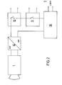
- the quotient pyrometer 1 is set in time intervals by a timing relay 9.
- the timing relay is controlled via the current consumption during printing, i.e. Coke press.
- the measured values resulting from the interval temperature measurement are recorded with a recorder 10.
- Time relay 9 and recorder 10 are mounted in a fixed position opposite the movable push rod.
- the necessary operative connection with the quotient pyrometer 1 is achieved by flexible lines 11 with automatic winding not shown.
- the recorder 10 is arranged in the driver's cab of the printing machine, not shown.
- each printing process takes place with the beginning of the current consumption With the intervals given by the time relay, a non-contact surface temperature measurement by each quotient pyrometer 1.
- the surface temperatures of the walls are usually between 1000 and 1300 C. In the oven itself there are temperatures between 900 and 1100 C.
- the pyrometer 1 is on those of the coke oven walls outgoing radiation calibrated. This is done with the help of a body of known radiation. This calibration process is also referred to as calibrating the measuring devices.
- the temperature values measured in the pyrometer 1 occur in the form of voltage values and are converted into ampere values in a converter 12.
- the output of the converter is between 0 and 20 mA.
- the output values go into printer 10, which is operated with alternating current (220 V, 50 Hz).
- the timing relay 9 as a pulse generator and a relay 13 are connected between printer 10 and converter 12.
- the relay 13 is closed when the current is drawn at the start of the printing process.
- the relay 13 is operated with alternating current (24 V, 50 Hz);
- the timing relay 9 is operated with the same current and operates as a pulse generator with a range between 0 to 20 seconds and is set to two seconds in the exemplary embodiment.
- a temperature profile is recorded by the temperature measurement according to the invention, ie the heating is checked on the coke oven chamber surface coming into contact with the coking coal and is consequently much more intensive than in the case of conventional measurements. Every manipulation on each individual furnace is accompanied by the recording of the temperature profile. The uncertainties of previous manual measurements in the accuracy and in the sequence of the measurements are eliminated. The accuracy and speed of the measurements are extreme high. With the help of the printer, a diagram is ejected, which the heating engineer can use immediately and immediately for checking and making corrections. Mechanical temperature measurement eliminates a number of manual tasks and has a significant rationalization effect.
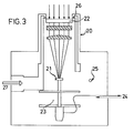
- Figure 3 shows a measuring head according to the invention, which consists of an optics 20 and a transducer 21 for absorbed heat radiation.
- the measuring head is arranged on the print head of the pressure rod in such a way that its window 22 of the optics 20 absorbs heat radiation in the same way as the window 3 according to FIGS. 1 and 2.
- the optics 20 concentrates the heat radiation falling through the window 22 onto the transducer 21, which is designed in any way as a temperature sensor. This can be the case in the form of a quotient pyrometer or in the simple form of a thermocouple.
- the converter 21 converts the heat radiation received into a current signal which is amplified in a preamplifier 23 which is arranged in the measuring head.
- the current signal amplified in this way is switched off via a cable 24! scoring supplied, which works in the same way as that of Figure 2.
- the evaluation unit includes a chart recorder.
- the measuring head according to the invention also has a temperature sensor for the temperature in the measuring head, with which an alarm is triggered when the predetermined permissible temperature limit values are exceeded.
- the entire measuring head is constantly cooled with water.
- the water is drawn off from a storage container with a pump and, after flowing through the measuring head, is circulated through air coolers.
- the water circulation is about! 100 rpm.
- the water supply in the measuring head is 25; draws.
- the supply line and drain line for the cooling water is provided in the area of the pressure rod with a corrosion-resistant jacket made of VA steel. The feed The supply and drain line for the cooling water is led along the push rod to the measuring head.
- air cooling is provided on the measuring head.
- the air emerges from an annular nozzle 26 at the window 22 and at the same time cools or cleans the window 22 of dust and contamination.
- the air line is laid together with the water supply and drain line on the push rod.
- the fourth line is a six-wire electrical cable to the measuring head, which has the task of supplying the amplifier 23 and receives the measuring signal and the signal from the temperature sensor in the measuring head.
- the cable 24 is flexible, at the same time armored or coated with PTFE (polytetrafluoroethylene).
- the armor is used for thermal insulation if the line 24 is directly exposed to the heat radiation or for insulation against the cooling water if the cable 24 is guided inside the water supply or discharge line.
- the cable 24 covered with PTFE 0 can take temperatures up to 400 ° C
- air cooling can also be provided for the cable 24.
- the air cooling can be designed in the same way as the water cooling.
- a protective tube is also provided for the line 24.
- the air supply to the measuring head is designated 27.
- all supply lines either lose their protective tubes and, like line 24, are inherently flexible or at least in a transition zone richly trained to the push rod.
- the flexible training allows winding on hose reels.
- Spring hose drums are preferably provided. There is a connection from the drums to the corresponding supply systems.
- the air is extracted from a compressor installed for the pneumatic locking of the coke oven doors as soon as a solenoid valve releases the air after the push rod movement begins.
- the evaluation unit (recorder or plotter) is put into operation.
- a limit switch is installed on the push rod for the air extraction and the start of work of the evaluation unit, which is triggered with the first movement of the push rod to obtain a sufficiently spread diagram for the measurement accuracy.
- the pump for the cooling water circuit is preferably operated with DC voltage (e.g. 12 V) to enable battery supply in the event of a power failure.
- DC voltage e.g. 12 V
- the measuring spot of the optics is 1 cm, the working range 0.9 mm wavelength. Distance changes of the optics to the wall surface, e.g. can be caused by the push rod, do not affect the measurement accuracy.
Landscapes
- Physics & Mathematics (AREA)
- General Physics & Mathematics (AREA)
- Spectroscopy & Molecular Physics (AREA)
- Chemical & Material Sciences (AREA)
- Engineering & Computer Science (AREA)
- Materials Engineering (AREA)
- Oil, Petroleum & Natural Gas (AREA)
- Organic Chemistry (AREA)
- Combustion & Propulsion (AREA)
- Radiation Pyrometers (AREA)
- Coke Industry (AREA)
- Investigating Or Analyzing Materials Using Thermal Means (AREA)
Applications Claiming Priority (2)
| Application Number | Priority Date | Filing Date | Title |
|---|---|---|---|
| DE3148314 | 1981-12-07 | ||
| DE19813148314 DE3148314A1 (de) | 1981-12-07 | 1981-12-07 | "vorrichtung zur temperaturmessung von koksofenkammerwaenden" |
Publications (2)
| Publication Number | Publication Date |
|---|---|
| EP0081219A2 true EP0081219A2 (fr) | 1983-06-15 |
| EP0081219A3 EP0081219A3 (fr) | 1983-07-20 |
Family
ID=6148056
Family Applications (1)
| Application Number | Title | Priority Date | Filing Date |
|---|---|---|---|
| EP82111240A Ceased EP0081219A3 (fr) | 1981-12-07 | 1982-12-04 | Dispositif pour mesurer la température des parois de la chambre d'un four à coke |
Country Status (6)
| Country | Link |
|---|---|
| US (1) | US4580908A (fr) |
| EP (1) | EP0081219A3 (fr) |
| JP (1) | JPS58502063A (fr) |
| DE (1) | DE3148314A1 (fr) |
| IN (1) | IN158142B (fr) |
| WO (1) | WO1983002156A1 (fr) |
Cited By (4)
| Publication number | Priority date | Publication date | Assignee | Title |
|---|---|---|---|---|
| EP0133175A3 (fr) * | 1983-07-19 | 1986-05-14 | CENTRE DE RECHERCHES METALLURGIQUES CENTRUM VOOR RESEARCH IN DE METALLURGIE Association sans but lucratif | Procédé de contrôle du chauffage des fours à coke |
| GB2188721A (en) * | 1986-04-04 | 1987-10-07 | British Steel Corp | Roll temperature measurement |
| US4780832A (en) * | 1984-08-22 | 1988-10-25 | Rolls-Royce Plc | Radiation probe and method of use |
| DE102005020328A1 (de) * | 2005-04-30 | 2006-11-09 | Rag Aktiengesellschaft | Temperaturmessung in Verkokungsöfen |
Families Citing this family (16)
| Publication number | Priority date | Publication date | Assignee | Title |
|---|---|---|---|---|
| BE897330A (fr) * | 1983-07-19 | 1984-01-19 | Centre Rech Metallurgique | Procede de controle du chauffage des fours a coke |
| DE3347244A1 (de) * | 1983-12-28 | 1985-07-11 | Dr. C. Otto & Co Gmbh, 4630 Bochum | Verfahren zum betrieb einer koksofenbatterie |
| JPS62203071A (ja) * | 1986-03-03 | 1987-09-07 | Agency Of Ind Science & Technol | 赤外センサ装置 |
| GB8909667D0 (en) * | 1989-04-27 | 1989-06-14 | Coal Industry Patents Ltd | Optical probes for fluidised beds |
| DE4039007A1 (de) * | 1989-12-06 | 1991-06-13 | Hitachi Ltd | Infrarottemperaturmessgeraet, eichverfahren fuer das geraet, infrarottemperaturbildmessmethode, geraet zur messung desselben, heizgeraet mit messgeraet, verfahren zur steuerung der erwaermungstemperatur, und vakuumbedampfungsgeraet mit infrarotem temperaturmessgeraet |
| DE4138308C2 (de) * | 1991-11-21 | 1995-02-23 | Veba Kraftwerke Ruhr | Hochtemperaturmeßeinrichtung |
| US5372618A (en) * | 1992-12-30 | 1994-12-13 | Combustion Engineering, Inc. | Temperature measuring device for a gasifier |
| US6354733B2 (en) | 1999-01-15 | 2002-03-12 | Ametex, Inc. | System and method for determining combustion temperature using infrared emissions |
| WO2000041512A2 (fr) * | 1999-01-15 | 2000-07-20 | Ametek Aerospace Products, Inc. | Systeme et procede pour determiner la temperature de combustion au moyen des emissions infrarouges |
| US6370486B1 (en) | 1999-01-15 | 2002-04-09 | En'urga Inc. | System and method for determining combustion temperature using infrared emissions |
| DE10307593A1 (de) * | 2002-03-18 | 2003-10-16 | Mannesmann Roehren Werke Ag | Verfahren zur Erfassung der Kammerwandtemperatur in Kokereianlagen |
| US6909495B2 (en) * | 2002-08-13 | 2005-06-21 | Diamond Power International, Inc. | Emissivity probe |
| JP4026529B2 (ja) * | 2003-04-10 | 2007-12-26 | 東京エレクトロン株式会社 | シャワーヘッド構造及び処理装置 |
| US7648927B2 (en) * | 2005-06-21 | 2010-01-19 | Applied Materials, Inc. | Method for forming silicon-containing materials during a photoexcitation deposition process |
| CN102277180B (zh) * | 2010-06-08 | 2013-06-26 | 上海梅山钢铁股份有限公司 | 一种分格蓄热室焦炉加热系统温度测量装置的安装结构 |
| CN114252302A (zh) * | 2021-11-22 | 2022-03-29 | 五冶集团上海有限公司 | 一种干熄焦炉斜道区在线测温及气体取样装置和方法 |
Family Cites Families (14)
| Publication number | Priority date | Publication date | Assignee | Title |
|---|---|---|---|---|
| US2814953A (en) * | 1955-01-10 | 1957-12-03 | Ambrose J Callaghan | Temperature measuring devices for furnaces and mounting therefor |
| NL277988A (fr) * | 1958-09-06 | |||
| US3101618A (en) * | 1960-11-15 | 1963-08-27 | Leeds & Northrup Co | Rotary kiln shell temperature scanning system |
| DE1225143B (de) * | 1962-10-18 | 1966-09-22 | Gewerk Auguste Victoria | Verfahren zur Bestimmung und Anzeige der Betriebstemperatur der Kammerwandungen von Koksoefen |
| DE1473305A1 (de) * | 1964-06-05 | 1969-04-10 | Polysius Gmbh | Einrichtung zur Temperaturmessung in einem Drehrohrofen |
| US3577784A (en) * | 1968-12-30 | 1971-05-04 | Koppers Co Inc | Method and apparatus for measuring coke oven flue wall temperatures |
| US3501380A (en) * | 1968-12-30 | 1970-03-17 | Koppers Co Inc | Method and apparatus for measuring the temperature of coke oven walls |
| US3805072A (en) * | 1969-09-18 | 1974-04-16 | Saint Gobain | Method and apparatus for determining the location of the edge of a ribbon of glass under production in a metal flotation furnace |
| DE2141711C2 (de) * | 1971-08-20 | 1973-09-27 | Hoesch Werke Ag, 4600 Dortmund | Vorrichtung zur Lichtsignal-Fortleitung |
| US3998616A (en) * | 1975-02-03 | 1976-12-21 | Ppg Industries, Inc. | Manufacture of flat glass having controlled width and nip width |
| JPS5835555B2 (ja) * | 1978-01-30 | 1983-08-03 | 新日本製鐵株式会社 | コ−クス炉炭化室壁温度測定方法 |
| US4344819A (en) * | 1980-06-23 | 1982-08-17 | Bethlehem Steel Corporation | Method of determining coke level |
| DE3104258A1 (de) * | 1981-02-07 | 1982-10-21 | Ruhrchemie Ag, 4200 Oberhausen | Vorrichtung zur messung von temperaturen in druckreaktoren |
| US4435093A (en) * | 1981-12-08 | 1984-03-06 | Bethlehem Steel Corporation | Pyrometer with sighting window cleanliness monitor |
-
1981
- 1981-12-07 DE DE19813148314 patent/DE3148314A1/de active Granted
-
1982
- 1982-12-04 US US06/527,652 patent/US4580908A/en not_active Expired - Fee Related
- 1982-12-04 EP EP82111240A patent/EP0081219A3/fr not_active Ceased
- 1982-12-04 WO PCT/DE1982/000228 patent/WO1983002156A1/fr not_active Ceased
- 1982-12-04 JP JP58500138A patent/JPS58502063A/ja active Pending
-
1983
- 1983-02-15 IN IN173/CAL/83A patent/IN158142B/en unknown
Cited By (5)
| Publication number | Priority date | Publication date | Assignee | Title |
|---|---|---|---|---|
| EP0133175A3 (fr) * | 1983-07-19 | 1986-05-14 | CENTRE DE RECHERCHES METALLURGIQUES CENTRUM VOOR RESEARCH IN DE METALLURGIE Association sans but lucratif | Procédé de contrôle du chauffage des fours à coke |
| US4780832A (en) * | 1984-08-22 | 1988-10-25 | Rolls-Royce Plc | Radiation probe and method of use |
| GB2188721A (en) * | 1986-04-04 | 1987-10-07 | British Steel Corp | Roll temperature measurement |
| DE102005020328A1 (de) * | 2005-04-30 | 2006-11-09 | Rag Aktiengesellschaft | Temperaturmessung in Verkokungsöfen |
| DE102005020328B4 (de) * | 2005-04-30 | 2008-04-30 | Rag Aktiengesellschaft | Temperaturmessung in Verkokungsöfen mittels einer Wärmebildkamera und Steuerungsvorrichtung hierfür |
Also Published As
| Publication number | Publication date |
|---|---|
| EP0081219A3 (fr) | 1983-07-20 |
| JPS58502063A (ja) | 1983-12-01 |
| WO1983002156A1 (fr) | 1983-06-23 |
| DE3148314C2 (fr) | 1989-07-13 |
| IN158142B (fr) | 1986-09-13 |
| DE3148314A1 (de) | 1983-06-09 |
| US4580908A (en) | 1986-04-08 |
Similar Documents
| Publication | Publication Date | Title |
|---|---|---|
| EP0081219A2 (fr) | Dispositif pour mesurer la température des parois de la chambre d'un four à coke | |
| EP0868656B1 (fr) | Procede et dispositif pour detecter des ondes electromagnetiques partant d'une masse en fusion | |
| DE2641382C2 (de) | Vorrichtung zur visuellen Untersuchung der feuerfesten Auskleidung einer Ofenkammer | |
| WO2011095377A1 (fr) | Dispositif de détection d'au moins une valeur de mesure sur un four, et four | |
| EP4386264A2 (fr) | Tête de sonde et ensemble sonde | |
| DE3318563A1 (de) | Verfahren und vorrichtung zum reparieren einer koksofenwand | |
| EP0064609B1 (fr) | Dispositif pour mesurer la distribution de la température le long de la surface intérieure de carneaux de fours à chambres | |
| DE2103048B2 (de) | Temperaturmesser | |
| EP0053227A1 (fr) | Dispositif pour la mesure de la température des parois de fours à coke | |
| DE19649264A1 (de) | Flammenbeobachtungsgerät | |
| DE3106568C2 (fr) | ||
| AT393165B (de) | Sonde zur bestimmung der temperaturen der waende der rauchzuege von koksoefen | |
| DE102016110170B3 (de) | Verzinkungsofen und Verfahren zum Betrieb eines Verzinkungsofens | |
| DE3000640A1 (de) | Vorrichtung zur messung der sinterzonentemperatur in einem drehrohrofen | |
| DE3622255C2 (de) | Verfahren und Vorrichtung zum Überwachen von Verbrennungsvorgängen in einem metallurgischen Ofen, insbesondere Hochofen | |
| DE102009031365B3 (de) | Wassergekühlte Gasbeprobungslanze | |
| DE895161C (de) | Einrichtung zum Messen der Temperatur des Stahlbades im blasenden Konverter | |
| LU83784A1 (de) | Strahlungsfuehler zum messen von temperaturen von erhitzten schuettguetern insbesondere von bituminoesem mischgut | |
| DE2021360A1 (de) | Verfahren und Vorrichtung zum UEberwachen einer Schmelze | |
| WO2000075614A1 (fr) | Dispositif de mesure pour la determination d'un parametre physique d'un milieu liquide a haute temperature | |
| EP1135971B1 (fr) | Procede et dispositif servant a detecter la diminution de productivite de composants d'un four a arc electrique | |
| DE102020135065A1 (de) | Sondenträger, Sondenanordnung, rauchgasführendes System, Verwendung und Verfahren | |
| DE29924558U1 (de) | Vorrichtung zur optischen Inspektion von Koksöfen | |
| DE1225143B (de) | Verfahren zur Bestimmung und Anzeige der Betriebstemperatur der Kammerwandungen von Koksoefen | |
| AT402570B (de) | Hochtemperaturmesseinrichtung |
Legal Events
| Date | Code | Title | Description |
|---|---|---|---|
| PUAI | Public reference made under article 153(3) epc to a published international application that has entered the european phase |
Free format text: ORIGINAL CODE: 0009012 |
|
| PUAL | Search report despatched |
Free format text: ORIGINAL CODE: 0009013 |
|
| AK | Designated contracting states |
Designated state(s): FR GB IT NL |
|
| AK | Designated contracting states |
Designated state(s): FR GB IT NL |
|
| 17P | Request for examination filed |
Effective date: 19830624 |
|
| STAA | Information on the status of an ep patent application or granted ep patent |
Free format text: STATUS: THE APPLICATION HAS BEEN REFUSED |
|
| 18R | Application refused |
Effective date: 19860628 |
|
| RIN1 | Information on inventor provided before grant (corrected) |
Inventor name: STEWEN, WILHELM, DR. ING. |