EP0081246A2 - Procédé et dispositif pour déterminer la température d'une masse dans un environnement hostile - Google Patents
Procédé et dispositif pour déterminer la température d'une masse dans un environnement hostile Download PDFInfo
- Publication number
- EP0081246A2 EP0081246A2 EP82111382A EP82111382A EP0081246A2 EP 0081246 A2 EP0081246 A2 EP 0081246A2 EP 82111382 A EP82111382 A EP 82111382A EP 82111382 A EP82111382 A EP 82111382A EP 0081246 A2 EP0081246 A2 EP 0081246A2
- Authority
- EP
- European Patent Office
- Prior art keywords
- mass
- temperature
- data
- plural
- window
- Prior art date
- Legal status (The legal status is an assumption and is not a legal conclusion. Google has not performed a legal analysis and makes no representation as to the accuracy of the status listed.)
- Withdrawn
Links
Images


Classifications
-
- G—PHYSICS
- G01—MEASURING; TESTING
- G01J—MEASUREMENT OF INTENSITY, VELOCITY, SPECTRAL CONTENT, POLARISATION, PHASE OR PULSE CHARACTERISTICS OF INFRARED, VISIBLE OR ULTRAVIOLET LIGHT; COLORIMETRY; RADIATION PYROMETRY
- G01J5/00—Radiation pyrometry, e.g. infrared or optical thermometry
- G01J5/02—Constructional details
- G01J5/05—Means for preventing contamination of the components of the optical system; Means for preventing obstruction of the radiation path
-
- C—CHEMISTRY; METALLURGY
- C10—PETROLEUM, GAS OR COKE INDUSTRIES; TECHNICAL GASES CONTAINING CARBON MONOXIDE; FUELS; LUBRICANTS; PEAT
- C10B—DESTRUCTIVE DISTILLATION OF CARBONACEOUS MATERIALS FOR PRODUCTION OF GAS, COKE, TAR, OR SIMILAR MATERIALS
- C10B45/00—Other details
-
- G—PHYSICS
- G01—MEASURING; TESTING
- G01J—MEASUREMENT OF INTENSITY, VELOCITY, SPECTRAL CONTENT, POLARISATION, PHASE OR PULSE CHARACTERISTICS OF INFRARED, VISIBLE OR ULTRAVIOLET LIGHT; COLORIMETRY; RADIATION PYROMETRY
- G01J5/00—Radiation pyrometry, e.g. infrared or optical thermometry
- G01J5/0044—Furnaces, ovens, kilns
-
- G—PHYSICS
- G01—MEASURING; TESTING
- G01J—MEASUREMENT OF INTENSITY, VELOCITY, SPECTRAL CONTENT, POLARISATION, PHASE OR PULSE CHARACTERISTICS OF INFRARED, VISIBLE OR ULTRAVIOLET LIGHT; COLORIMETRY; RADIATION PYROMETRY
- G01J5/00—Radiation pyrometry, e.g. infrared or optical thermometry
- G01J5/02—Constructional details
- G01J5/025—Interfacing a pyrometer to an external device or network; User interface
-
- G—PHYSICS
- G01—MEASURING; TESTING
- G01J—MEASUREMENT OF INTENSITY, VELOCITY, SPECTRAL CONTENT, POLARISATION, PHASE OR PULSE CHARACTERISTICS OF INFRARED, VISIBLE OR ULTRAVIOLET LIGHT; COLORIMETRY; RADIATION PYROMETRY
- G01J5/00—Radiation pyrometry, e.g. infrared or optical thermometry
- G01J5/02—Constructional details
- G01J5/06—Arrangements for eliminating effects of disturbing radiation; Arrangements for compensating changes in sensitivity
- G01J5/061—Arrangements for eliminating effects of disturbing radiation; Arrangements for compensating changes in sensitivity by controlling the temperature of the apparatus or parts thereof, e.g. using cooling means or thermostats
-
- G—PHYSICS
- G01—MEASURING; TESTING
- G01J—MEASUREMENT OF INTENSITY, VELOCITY, SPECTRAL CONTENT, POLARISATION, PHASE OR PULSE CHARACTERISTICS OF INFRARED, VISIBLE OR ULTRAVIOLET LIGHT; COLORIMETRY; RADIATION PYROMETRY
- G01J5/00—Radiation pyrometry, e.g. infrared or optical thermometry
- G01J5/80—Calibration
-
- G—PHYSICS
- G01—MEASURING; TESTING
- G01J—MEASUREMENT OF INTENSITY, VELOCITY, SPECTRAL CONTENT, POLARISATION, PHASE OR PULSE CHARACTERISTICS OF INFRARED, VISIBLE OR ULTRAVIOLET LIGHT; COLORIMETRY; RADIATION PYROMETRY
- G01J5/00—Radiation pyrometry, e.g. infrared or optical thermometry
- G01J5/90—Testing, inspecting or checking operation of radiation pyrometers
Definitions
- This invention relates to temperature measurements. More particularly, this invention relates to a computer-based method and system for determining temperature of an irradiant mass movable through process means in a hostile environment.
- the invention is exemplified hereinafter which will automatically determine temperature of coke in the environment of a coke guide or coke oven.
- the invention may also be used in other industries having process means in a hostile environment such as at cement kilns and the like.
- a door machine positions a coke guide at a selected oven, removes a coke side oven door. Then an irradiant coke mass is pushed through the coke guide into a quench car. It is important in coke production to obtain accurate and reliable temperature measurements of the coke oven and/or the coke mass continuously during coking and/or pushing. Accurate temperature measurements allow the operator to identify problems maximize production, minimize pollution problems and prioritize maintenance scheduling. In-furnace thermocouples are not practical for continuously monitoring coke oven temperatures because of the large physical size of the ovens and the fact that a hundred or more coke ovens may constitute a normal size battery. An alternative is to use a pyrometer to measure the temperature of coke as it is pushed from the coke oven and relate it to coke oven wall temperature.
- Another object of this invention is to provide a method and system for automatically determining the temperature of an irradiant mass movable through process means in a hostile environment which will have improved long-term accuracy and reliability.
- Yet another object of this invention is to provide a method and system of determining the temperature of an irradiant mass movable through process means in a hostile environment which will require substantially less maintenance than heretofore.
- Still another object of this invention is to provide a method and system for automatically determining the temperature of an irradiant mass movable through process means which will enable an operator to improve coke quality, increase coke battery life, reduce fuel consumption, reduce emissions and prioritize maintenance.
- a production-worthy system comprising two computer-based subsystems for determining temperature of an irradiant mass movable through process means in a hostile environment, such as temperature of coke in the environment of a coke guide and coke oven in a battery of ovens.
- First subsystem which is carried on a movable coke guide/door machine combination, includes one or more coke guide pyrometers arranged vertically, each with a sighting window monitor to detect optical errors, an onboard computerized and cooled electronics package for acquiring and processing coke temperature coke data, during, for example, a coke pushing cycle, and automatically detecting same-for pyrometer drift and optical errors caused by the hostile environment, and automatically correcting for these errors, and further including a plug-in portable terminal with a printer.
- the second computer-based subsystem is stationed in a central office, or elsewhere, having a base computer package with various computation and storage capabilities and includes a CRT control terminal for operator interaction with the entire system, a line printer and a printer/plotter.
- Two-way data communication between the two subsystems is exemplified as a two-way radio link.
- Each subsystem logs both coke level data and coke vertical and horizontal temperature profile data and alarm messages.
- Tabular printouts of coke mass temperature, coke level and diagnostic data are provided by both the portable terminal printer in the on-board subsystem and the base computer printers.
- Graphical displays are also provided by the base computer subsystem of coke level, temperature and summary data, oven push schedules and/or self-diagnostic message of various process and measurement operations.
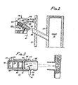
- FIGS. 1 to 13 and particularly to FIG. 1 the production-worthy computer-based system for determining mass temperature in a hostile environment, or simply overall system 10 of this invention, is shown, for example, installed on the coke side of one of numerous coke ovens in a coke oven battery (not shown).
- Overall system 10 is made up of two subsystems, namely, on-board subsystem 11 carried by a movable coke guide/door machine combination from oven-to-oven, and base computer subsystem 12 stationed in a central office (not shown) having a base computer package.
- the specific functions of each computerized subsystem 11,12 may be apportioned differently than described below, depending on user preference.
- Coke guide 14 is positioned at the coke side of the selected oven site by door machine 15 after first removing the coke side oven door. Because uniform vertical and horizontal coke temperature along the length of the individual ovens is an important coke making parameter, it is of great importance that coke temperature at coke guide 14, or elsewhere, be continuously obtained on an accurate and reliable basis. Otherwise, the entire coke making process control will suffer, along with coke quality, operating and maintenance cost, and ultimate profitability.
- production-worthy computer-bases subsystem 11 is provided with a group of five pyrometer heads 16-1,-2,-3,-4,-5 mounted vertically on coke guide 14, each at a different level, and associated electronic circuit means, including means for self-calibrating the coke temperature signal, all contained in equipment enclosure 17 mounted on door machine 15 with interconnecting electronic and pneumatic services described below.
- Each device 16-1,-2,-3,-4,-5, and 17 is constructed of materials suitable to resist their respective hostile environments.
- Pyrometer heads 16-1,-2,-3,-4,-5 each have a housing purged ⁇ of dust and dirt and is cooled to some extent by air on line 18 from air purge source 19 carried on door machine 15.
- equipment enclosure 17 has a housing also purged of dust and dirt and cooled to a limited extent by air on line 20 from source 19.
- air conditioner 21 of sufficient capacity may, if desired, be substituted for the cooling source from air line 20.
- a typical pyrometer head 16 located at each vertical level includes a pyrometer housing 22, which is resistant to hostile environmental elements and purged by air line 18 from source 19, an optical pyrometer assembly 23 in housing 22, tubular adjustable mount 24 for aiming pyrometer assembly 23 to pick up irradiant coke image 25 through a separate sight tube 26 at each vertical level.
- Sight tube 26 is located between pollution barrier 27 and an outer wall of coke guide 14 which form part of the entire structure of coke guide 14/door machine 15 combination.
- Included in pyrometer assembly 23 is a tubular housing 28 adapted to be slip-fitted into tubular opening 29 of adjustable mount 24.
- Tubular housing 28 closed at end 30, includes coke sighting window 31 made of quartz glass at the opposite end which is subject to optical error by hostile environmental matter 32, such as a dirt film buildup on window 31.
- coke sighting window 31 made of quartz glass at the opposite end which is subject to optical error by hostile environmental matter 32, such as a dirt film buildup on window 31.
- lens 33 for focusing irradiant coke image on an infrared pyrometer detector 34 which generates a mass or coke temperature signal on line 35, and pyrometer 28 ambient temperature sensor 36, such as a posistor device, which generates a pyrometer ambient temperature signal on line 37.
- WCM means 38 has a WCM light assembly 39 with a stable source of light which is transmitted through light conducting fibre optic 40.
- Light conducting fibre optic 40 has an end outside coke sighting window 31 aimed toward pyrometer detector 34 inside housing 28.
- the stable light source inside monitor light assembly 39 is turned on by a WCM control signal on line 41 to determine the amount of window optical error introduced in the coke temperature signal on line 35 caused by the build up of dirt film 32 on coke sighting window 31 and similar matter on the end of fibre optic 40.
- the WCM control signal is turned off, such as during normal pyrometer operation, the WCM ceases to function.
- adjustable mount 24 Also included in adjustable mount 24 is an air purge manifold 42 encircling the tubular portion of mount 24 with a first plurality of air purge jets 43 directed toward dirt film 32 on window 31.
- a second set of air purge jets 44 is aimed in the end direction of WCM light conducting fibre optic 40.
- the combined effect of air purge jets 43,44 tends to minimize dirt from entering pyrometer mount 24.
- an air wiping effect tends to clean equally the dirt film 32 from coke sighting window 31 and from the end of fibre optic 40.
- over-temperature switch 45 which generates an over-temperature signal on line 46 whenever the ambient temperature inside housing 22 approaches a temperature which will cause permanent damage to electronics components therein, such as damage to detector 34 and sensor 36.
- circuit means shown in equipment enclosure 17 may be individual hardwired circuits, or one or more may be incorporated in the microcomputer shown in subsystem 11 and programmed to perform the same processing, correction and self-diagnostic functions as shown and described herein.
- the five pyrometer heads 16-1,-2,-3,-4,-5 each output a separate coke temperature signal on lines 35-1,-2, - 3,-4,-5, representing coke temperature at its respective vertical level in coke guide 14.
- Each coke temperature signal is susceptible to two forms of errors, namely, pyrometer ambient temperature drift error at its particular level and window optical error.
- the coke temperature signals on lines 35-1,-2,-3,-4,-5 are fed to pyrometer electronic circuits 47 which include conventional linearizing and scaling circuits for accommodating the characteristics of each coke temperature sensing infrared optical pyrometer detector 34-1,-2,-3,-4,-5, (shown as 34 in FIGS. 2,3).
- Pyrometer electronic circuits 47 are modified to correct each of the five pyrometer signals for pyrometer ambient temperature drift as a function of respective pyrometer ambient temperature signals received on lines 37-1,-2,-3,-4,-5, thereby outputing a corresponding drift corrected coke temperature signal on each line 48-1,2,-3,-4,-5. These signals are fed to computer analog input device 49 and then to microcomputer 50 for processing as described below. Computer analog outputs 57 are switched under control of microcomputer 50 to act as a source of a calibration reference in place of the coke temperature signals for determining the stability of microcomputer 50 data acquisition system.
- Equipment enclosure 17 includes a five-channel window cleanliness monitor (WCM) circuits 52, which output five corresponding WCM control signals on lines 41-1,-2, -3,-4,-5, respectively, to one of the five window cleanliness monitor light assembly 39, described above in connection with pyrometer head 16 shown in FIGS. 2 and 3.
- WCM control signals 41-1,-2,-3,-4,-5 are generated by computer digital outputs 53 which, under control of microcomputer 50, generate five corres- .ponding WCM on-off control signals fed on line 54-1,-2, -3,-4,-5, to WCM circuits 52.
- each WCM light source 39 in each pyrometer assembly is turned on and off, respectively, before and after coke mass 13 movement starts through coke guide 14 as determined by coke guide 14 movement. This establishes a basis for detecting the amount of optical error in each of the five drift-corrected coke temperature signals on lines 48-1,-2, -3,-4,-5, caused by dirt film 32 on coke mass sighting window 31 as will be explained below.
- Computer digital outputs 53 also under control of microcomputer 50, generate a pyrometer reset control signal 55 to the five pyrometer electronic circuits 47 to reset the temperature reading at the end of a predetermined time period.
- on-board subsystem 11 makes certain self-diagnostic checks.
- the five pyrometer over-temperature signals on lines 46-1,-2,-3, -4,-5 which originate from one each of the five over-temperature switches (shown as 45 in FIG. 2), are fed to pyrometer over-temperature switch circuits 56.
- Circuits 56 in turn fed five diagnostic over-temperature signals on lines 57-1,-2, -3,-4,-5, to an input of computer digital inputs 58, through microcomputer 50 and display diagnostic messages on, for example alarm device 59 or other computer peripherals, signifying a condition that its respective pyrometer head housing 22 has reached its safe limit before damaging the contents of housing 22.
- air purge flow switch 60 which senses and signals an alarm message on line 61 concerning the failure of air purge source 19. Such failure ceases to supply purge air to jet wipes and cooling air to each pyrometer head 16-1,-2,-3,-4,-5, and purge air on line 20 to equipment enclosure 17 when used.
- the air flow loss alarm message is also fed through digital inputs 58, microcomputer 50, and alarm device 59 and other peripherals.
- Still another self-diagnostic feature is generated by air conditioner 62 whenever cooling air supply is lost to equipment enclosure 17.
- a contact closure in air conditioner 62 sends an air conditioning failure alarm signal over line 63 to digital inputs 58, microcomputer 50 and alarm device 59 and other peripherals. This alarm signal also alerts the user that uncorrectable errors are present and failure of electronic circuits in equipment enclosure 17 is imminent.
- Machine control relays 64 provide interlock control signals for microcomputer 50 to use signifying that a sliding frame (not identified) holding all five pyrometer heads 16-1,-2, -3,-4,-5 has been in place and that coke guide 14 is in place ready to receive the coke mass 13 to be pushed by the pusher machine. If any of the foregoing conditions are not met, then data is not collected for that oven.
- a digital timer 66 is provided for generating digital timing signals at predetermined intervals corresponding to coke mass movement distance covered by the pusher machine ram and the total travel time by the pusher. Timer 66 is started and stopped when the coke pushing cycle is started and stopped. Digital timer 66 signals are also used by microcomputer 50 to control the data acquisition rate of the five coke mass temperature signals according to computer programs described below.
- Computer-based onboard subsystem 11 also includes within the door machine 15 operator's control device 67 for generating a coke oven identification number, used by base computer subsystem 12 described below.
- Device 67 also includes a reset function for microcomputer 50 which can be activated in response to an error diagnostic message.
- printer type portable service terminal 68 which is plugged in the onboard subsystem 11 for data logging, servicing, diagnostic and maintenance purposes. Use of portable service terminal 68 will be described below in connection with FIGS. 5,6,7 illustrations of terminal 68 printouts.
- Microcomputer 50 in on-board subsystem 11 is provided with storage means 69 of adequate capacity to perform the variety of functions described below.
- Microcomputer 50 is operated under control of computer programs 70 with a functional flow chart thereof shown in FIG. 4.
- Bidirectional data communications are handled through modem 71 and two-way radio link 72 to and from the base computer subsystem 12.
- Subsystem 12 comprises two-way radio link 73, for bidirectional communication to and from on-board subsystem 11, two-way modem 74, minicomputer 75, short-term storage device 76, long-term storage device 77, and computer programs 78.
- Programs 78 are illustrated in FIG. 8 which is a functional flow chart for.all operating control communications. These are used to acquire coke mass temperature data, machine functions, to perform data calculations, document the generated oven pushing schedules, summarize data, diagnostics, and prioritize maintenance requirements.
- minicomputer peripheral 79 having a CRT display 80 and terminal 81 for providing operator interaction and requests.
- a line printer 82 for displaying FIG. 11,12,13 tabular data printouts, and a printer plotter 83 for producing graphical printouts shown in FIGS. 9 and 10A-D.
- microcomputer 50 storage 69 During a push, a total of approximately 40 temperature readings are obtained per pyrometer. These data are temporarily stored in microcomputer 50 storage 69 along with data from the previous four pushes.
- microcomputer 50 In addition to controlling coke temperature data collection, microcomputer 50 also monitors the cleanliness of pyrometer windows 31 (window cleanliness monitor), provides self-diagnostic checks, and if desired, performs a self-calibration of overall system 10. Self-calibration is an important function on some installations. These features of subsystem 11 allow the equipment to operate reliably and with minimum maintenance. Details of each of these unique features follows:
- step 95 which controls data communications to and from base minicomputer 75 in subsystem 12 in response to operator interaction.
- step 96 which calls for automatic coke level and temperature data collection from pyrometer heads 16-1,-2,-3,-4,-5 into storage 69 of microcomputer 50 for use on request from subsystem 12.
- step 97 calls for a window cleanliness monitor routine having two parts, namely, part one, window cleanliness and part two, pyrometer alignment.
- part one system errors caused by electronic drift and/or dirt 32 buildup on window 31 are accounted for in the WCM feature which combine hardware and software to compensate for both types of errors as well as alarm personnel when window 31 maintenance is required.
- WCM details are shown in FIGS. 2 and 3 described above.
- Microcomputer 50 will, upon command, generate the monitor light on-off control signal and cause monitor light assembly 39 to cause monitor light to enter pyrometer 23. If the pyrometer window becomes dirty and/or the pyrometer electronics in circuits 47 drift, pyrometer circuits 47 the outputted voltage generated by the WCM monitor light will change.
- Each of the five pyrometer heads 16-1,-2,-3,-4,-5 is set to output a voltage equal to a temperature reading of 1800°F. under clean window 31 conditions when the WCM is activated.
- the WCM is activated, its output voltage checked by the microcomputer, and the data is stored in a "WCM Data Block". These data are analyzed by microcomputer 50 to establish if the pyrometers are functioning properly and whether window 31 cleaning is required.
- the tip of fibre optic 40 light guide can also get dirty, but by proper positioning, the rate of dirt buildup on the fibre optic 40 tip matches the rate of buildup on window 31, thereby not impairing the WCM function.
- the pyrometer window is considered “dirty” and a message is output by microcomputer 50 - "WCM ALARM PYRO (I)". Further, if the pyrometer reading is less than 1500°F or greater than 1820 0 F, the pyrometer is considered “defective” and a message is output - "PYROMETER (I) DEFECTIVE".
- the microcomputer loops back to sequentially test pyrometers 2 through 5. It then returns to the main program.
- Messages and printouts of WCM may be obtained on-board by proceeding to steps 98 and 99 when plugging in portable service terminal 68.
- this information is logged in base computer subsystem 12 described below.
- step 97 covers the pyrometer head 16-1,2,-3 alignment check subroutine mentioned above.
- Proper alignment of pyrometer heads 16-1,-2,-3 with their respective sight tubes 26 is critical because temperature measurement errors would result if the pyrometer were not completely sighted on coke mass 13 during a push. Due to the logic involved in establishing pyrometer alignment, this check can only be performed for pyrometer heads 16-1,-2, and -3. Pyrometer heads 16-4 and -5, which monitor the coke line, cannot be evaluated because these pyrometers may not be continuously sighted on coke during a push if the oven had been improperly charged.
- Alignment conditions for pyrometer heads 16-1,-2 and -3 are established using the data stored in the WCM data block and the temperature data block. Coke temperature data collected at the mid-point of a push is averaged for each of the three pyrometers and sequentially compared to a temperature of 1500°F. If the average coke temperature for a given pyrometer is greater than 1500°F., the pyrometer is considered to be properly aligned. If the average coke temperature is less than 1500°F but the WCM measurement for that pyrometer is between 1500 and 1820°F (indicating normal pyrometer operation), the pyrometer is improperly aligned and microcomputer 50 outputs a message - "HEAD OUT OF ALIGNMENT PYRO (I)".
- microcomputer 50 After an analysis of the data for pyrometer head 16-1, microcomputer 50 loops back to sequentially test pyrometer heads 16-2 and -3 before returning to the main program.
- Messages and printouts of pyrometer head alignment may be obtained onboard by proceeding to steps 98 and 99 when plugging in portable service terminal 68.
- this information is logged in base computer subsystem 12 described below.
- Subsystem 11 computer programs 70 proceed to another application program, step 100 where subsystem "Self-Calibration" subroutine is performed.
- WCM window cleanliness monitor check may be used by microcomputer 50 to automatically adjust the pyrometer head 16-1,-2,-3,-4,-5 calibration.
- This "Self-Calibration" subroutine initially fetches the data located in the WCM data block and checks whether the WCM reading for a particular pyrometer head 16-1,-2,-3,4,-5 falls within an acceptable operating range from 1760 to 1820°F. If it is within the normal range, the WCM reading is then divided into 1800OF (the original pyrometer output when sighted through a clean window on the WCM lamp 39) to develop a "Scale Factor" for that pyrometer. This scale factor is approximately linear for small variations of the WCM reading near 1800°F. All temperature data subsequently collected with that pyrometer is then "adjusted” by multiplying the temperature data by the scale factor. Thus, as the window gets dirty, or other slowly varying functions change, the increased or decreased temperature measurement sensitivity is automatically compensated for.
- the WCM subroutine (previously run in step 90 will have already output a message for maintenance assistance). Temperature data provided by that pyrometer is then multiplied by a scale factor equal to 1.0 which outputs these data as collected. Finally, a message is output along with the data which indicates whether the data was adjusted and the scale factor used. Microcomputer 50 sequentially checks the remaining pyrometers before returning to the main program.
- step 101 Still another applications program is performed in step 101 where subsystem 11 "Self-Diagnostics" subroutine is performed covering three different parts and five subparts of one of the parts.
- step 101 operation of the subsystem 11 is made more reliable through the use of self-diagnostics which are performed automatically by microcomputer 50.
- microcomputer 50 checks the following substep parameters to assure normal equipment operation:
- "Sensor Diagnostics" subroutine provides a way to check the status of the air purge system 19, as well as the temperature of both the main enclosure 17 and the pyrometer heads 16-1,-2,-3,-4,-5, enclosures.
- the air purge system serves two functions: (1) cooling of the pyrometer head enclosures to maintain their inside temperature below the rated ambient temperature (180 0 F) of the pyrometers and (2) purging of the pyrometer windows 31 to minimize dirt buildup on the windows. Due to high temperature and heavy dust conditions previaling during a coke oven push, it is necessary to continuously monitor the air purge rate and the temperature of the enclosures to provide reliable system operation.
- the temperature of the main enclosure 17 is also monitored to assure that the onboard electronics is operating in the desired temperature range of 50 to 90°F. Temperature extremes in either direction could cause the electronics to drift resulting in measurement errors.
- microcomputer 50 After the sensor diagnostics routines, microcomputer 50 returns to the main program.
- An "RF Sniffer” subroutine follows. Transmission of data and messages between the coke guide 14/door machine 15 and base computer subsystem 12 is done by an RF transceiver 72. To reliably transmit these data, the RF transmitter power must exceed a pre-set level. An RF Sniffer monitors the output power of the transmitter during regular operation as follows: Microcomputer 50 checks the sniffer output and, if the power level is low, will check the sniffer output again. A failure of both tests prompts the microcomputer to set a local message "RF Carrier Failure".
- a “Data Acquisition Diagnostic” subroutine follows.
- the “Data Acquisition Diagnostic” subroutine provides a method to automatically check the operation of the data acquisition section of the onboard microcomputer.
- “Data Acquisition Diagnostic” subroutine provides the following steps:
- Messages and printouts of selfdiagnostics may be' obtained on-board by proceeding to steps 98 and 99 when plugging in portable service terminal 68.
- this information is logged in base computer subsystem 12 described below.
- On-board microcomputer 50 also performs step 102 which calls for formatting data to the specific oven that was pushed according to the oven push schedule. This subroutine returns to the main program, then may proceed to step 98 and 99 described above for use of the messages and printouts provided.
- step 103 The final step in on-board microcomputer 50 programming is step 103 where temporary data storage is updated for each of the five pushes placed in storage 69, then returns to the main program.
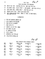
- FIG. 5 is a typical heading printed on a sheet which is self-explanatory.
- the diagnostic codes are shown in FIG. 7.
- FIG. 6 shows a typical tabular printout of raw coke temperature data for a selected oven where window cleanliness temperature measurements are obtained before the push is started and when WCM light control signal was "on".
- Pyrometer head 16-4 has a low WCM reading indicating a dirty window.
- the second and subsequent pyrometer head reading of coke temperature appear in columns under the WCM temperature which tabulated from intervals 1 to 47 when WCM light control signal was "off".
- FIG. 7 shows a typicai printout of the self-diagnostic features of subsystem 11 with the heading listing for "Help Task", followed by a listing of "Tasks Available For Operator” which are self-explanatory.
- “Diagnostic” under which each of the diagnostic code numbers that will be printed, for example, in the heading shown in FIG. 5. Otherwise the same Help Tasks are transmitted to and used in base computer subsystem 12.
- minicomputer 75 located in a central office, the onboard microcomputer 50 aids in transmitting the data, via an RF transceiver 73, to minicomputer 75.
- the minicomputer 75 checks the data validity, processes the data, outputs graphs of the coke line (height of coke in the oven) and the vertical and horizontal temperature variations within an oven, develops summary management and maintenance reports, stores data for up to 600 pushes, and reports any diagnostic system problems. See FIGS. 9-13. These data can be used by operating personnel to prioritize coke oven maintenance, establish the heating practices of the coke oven battery, and monitor the efficiency of the coal charging operation.
- Base computer subsystem 12 minicomputer 75 operating system executive subroutine is called for in Step 110. This is followed by communications programs for radio line 73 called for in step 111 and modem 74 interface programs called for in step 112, both step responsive to operator interaction at terminal 81 to control passage to and from subsystem 11 of all data through the entire two-way data communications radio links.
- Step 113 calls for initialization programs and step 114 calls for utility programs core, both in response to step 110.
- step 113 there is applications program step 115 which covers simultaneously three essential automatic applications programs in steps 116,118 and 119.
- Step 116 calls for a subroutine which automatically gets diagnostic messages from onboard microcomputer 50 obtained as mentioned above, then step 117 calls for printing these diagnostic messages on line printer 82. This subroutine then returns to the main program.
- Step 118 calls for a subroutine which initially automatically gets coke temperature data from onboard microcomputer 50, obtained as mentioned above, then later stores in short-term storage 76 coke temperature data for approximately 600 coke oven pushes identified from a coke oven pushing schedule stored in minicomputer 75 from data generated by device 67 in subsystem 11.
- Step 119 calls for a subroutine which automatically computes data, obtained as mentioned above, and performs the following analyses:
- step 119 subroutine calls for storing summary data in long term storage 77 for historical use, then exiting same to step 120.
- Step 120 calls for a subroutine which accommodates operator interface requests through terminal 81 to obtain any of the stored data and present it in any of three ways called for in steps 121,122,123.
- step 121 subroutine which calls for printing summary statistics on line printer 82 of the like appearing in FIG. 12 base minicomputer push schedule output and others not shown. This subroutine loops back to step 120.
- step 122 subroutine which calls for printing tabular data on line printer 82 of coke line and vertical and horizontal oven temperature data substantially similar to that of FIG. 6 under a data dump task. This subroutine loops back to step 120.
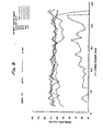
- Step 123 calls for a subroutine which will plot graphical displays on printer/plotter 83 of coke line and vertical and horizontal coke temperature data of the like appearing in FIGS. 9 and 10A to 10D.
- FIG. 9 illustrates horizontal coke temperature profile plots at each of the five levels of pyrometer heads 16-1,-2,-3,-4,-5 above the selected coke oven sole, or floor, according to the legend in the upper right-hand corner.
- Five-point vertical temperature profile of the coke mass may easily be obtained from the five different coke temperature traces by observing data points at any vertical line along the length of the selected oven.
- Coke level profile may be observed by the temperature trace of the highest level pyrometer head 16-5.
- FIG. 9 also shows a plot of an irregularly filled and leveled coal charge, as indicated by the absence of temperature measured by the pyrometer head at the .18 foot level.
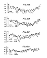
- FIGS. 10A to 10D are similar plots of the FIG. 9 coke temperature data exemplifying the coke level and temperature data of the same oven in four successive charging and coking cycles in the same battery of coke ovens.
- Step 123 subroutine loops back to step 120, thus completing the description of computer program 78 of the base computer subsystem 12, as well as the entire system 10.
Landscapes
- Physics & Mathematics (AREA)
- General Physics & Mathematics (AREA)
- Spectroscopy & Molecular Physics (AREA)
- Chemical & Material Sciences (AREA)
- Engineering & Computer Science (AREA)
- Human Computer Interaction (AREA)
- Materials Engineering (AREA)
- Oil, Petroleum & Natural Gas (AREA)
- Organic Chemistry (AREA)
- Radiation Pyrometers (AREA)
- Photometry And Measurement Of Optical Pulse Characteristics (AREA)
Applications Claiming Priority (2)
| Application Number | Priority Date | Filing Date | Title |
|---|---|---|---|
| US32877581A | 1981-12-08 | 1981-12-08 | |
| US328775 | 1981-12-08 |
Publications (2)
| Publication Number | Publication Date |
|---|---|
| EP0081246A2 true EP0081246A2 (fr) | 1983-06-15 |
| EP0081246A3 EP0081246A3 (fr) | 1984-07-18 |
Family
ID=23282390
Family Applications (1)
| Application Number | Title | Priority Date | Filing Date |
|---|---|---|---|
| EP82111382A Withdrawn EP0081246A3 (fr) | 1981-12-08 | 1982-12-08 | Procédé et dispositif pour déterminer la température d'une masse dans un environnement hostile |
Country Status (6)
| Country | Link |
|---|---|
| EP (1) | EP0081246A3 (fr) |
| JP (1) | JPS58109825A (fr) |
| AU (1) | AU9161482A (fr) |
| BR (1) | BR8207098A (fr) |
| CA (1) | CA1183267A (fr) |
| ZA (1) | ZA828269B (fr) |
Cited By (7)
| Publication number | Priority date | Publication date | Assignee | Title |
|---|---|---|---|---|
| US4980028A (en) * | 1983-03-29 | 1990-12-25 | Mitsubishi Kasei Corporation | Method of controlling fuel for a coke oven |
| WO2012158114A1 (fr) | 2011-05-18 | 2012-11-22 | Bioendev Ab | Procédé de surveillance et de contrôle d'une température de torréfaction |
| WO2016199059A1 (fr) * | 2015-06-12 | 2016-12-15 | Baraldi S.R.L. | Système de commande d'une installation technologique |
| US9580665B2 (en) | 2011-05-18 | 2017-02-28 | Bioendev Ab | Countercurrent oxygen enhanced torrefaction |
| CN107543613A (zh) * | 2017-08-23 | 2018-01-05 | 西安科技大学 | 一种井下红外测温精度影响因素测试装置及测试方法 |
| CN114441050A (zh) * | 2022-01-26 | 2022-05-06 | 西安应用光学研究所 | 一种基于旋转挡片的热像仪实时非均匀性校正方法 |
| CN119901380A (zh) * | 2025-01-09 | 2025-04-29 | 中国矿业大学 | 一种基于粉尘补偿的除尘设备温度成像检测系统及方法 |
Family Cites Families (2)
| Publication number | Priority date | Publication date | Assignee | Title |
|---|---|---|---|---|
| US3501380A (en) * | 1968-12-30 | 1970-03-17 | Koppers Co Inc | Method and apparatus for measuring the temperature of coke oven walls |
| US4344819A (en) * | 1980-06-23 | 1982-08-17 | Bethlehem Steel Corporation | Method of determining coke level |
-
1982
- 1982-11-11 ZA ZA828269A patent/ZA828269B/xx unknown
- 1982-12-04 JP JP57212107A patent/JPS58109825A/ja active Pending
- 1982-12-06 CA CA000417046A patent/CA1183267A/fr not_active Expired
- 1982-12-07 AU AU91614/82A patent/AU9161482A/en not_active Abandoned
- 1982-12-07 BR BR8207098A patent/BR8207098A/pt unknown
- 1982-12-08 EP EP82111382A patent/EP0081246A3/fr not_active Withdrawn
Cited By (11)
| Publication number | Priority date | Publication date | Assignee | Title |
|---|---|---|---|---|
| US4980028A (en) * | 1983-03-29 | 1990-12-25 | Mitsubishi Kasei Corporation | Method of controlling fuel for a coke oven |
| WO2012158114A1 (fr) | 2011-05-18 | 2012-11-22 | Bioendev Ab | Procédé de surveillance et de contrôle d'une température de torréfaction |
| EP2710099A4 (fr) * | 2011-05-18 | 2015-03-11 | Bioendev Ab | Procédé de surveillance et de contrôle d'une température de torréfaction |
| RU2593988C2 (ru) * | 2011-05-18 | 2016-08-10 | Биоэндев Аб | Способ контроля и управления температурой обжига |
| US9580665B2 (en) | 2011-05-18 | 2017-02-28 | Bioendev Ab | Countercurrent oxygen enhanced torrefaction |
| US9926507B2 (en) | 2011-05-18 | 2018-03-27 | Bioendev Ab | Method for monitoring and control of torrefaction temperature |
| WO2016199059A1 (fr) * | 2015-06-12 | 2016-12-15 | Baraldi S.R.L. | Système de commande d'une installation technologique |
| CN107543613A (zh) * | 2017-08-23 | 2018-01-05 | 西安科技大学 | 一种井下红外测温精度影响因素测试装置及测试方法 |
| CN107543613B (zh) * | 2017-08-23 | 2024-02-02 | 西安科技大学 | 一种井下红外测温精度影响因素测试装置及测试方法 |
| CN114441050A (zh) * | 2022-01-26 | 2022-05-06 | 西安应用光学研究所 | 一种基于旋转挡片的热像仪实时非均匀性校正方法 |
| CN119901380A (zh) * | 2025-01-09 | 2025-04-29 | 中国矿业大学 | 一种基于粉尘补偿的除尘设备温度成像检测系统及方法 |
Also Published As
| Publication number | Publication date |
|---|---|
| ZA828269B (en) | 1983-09-28 |
| JPS58109825A (ja) | 1983-06-30 |
| EP0081246A3 (fr) | 1984-07-18 |
| AU9161482A (en) | 1983-06-16 |
| CA1183267A (fr) | 1985-02-26 |
| BR8207098A (pt) | 1983-10-11 |
Similar Documents
| Publication | Publication Date | Title |
|---|---|---|
| US4617638A (en) | Method and system for determining mass temperature in a hostile environment | |
| CA1183268A (fr) | Pyrometre a controle de clarte des regards | |
| AU610919B2 (en) | Diagnostic system for combustion controller | |
| EP0081246A2 (fr) | Procédé et dispositif pour déterminer la température d'une masse dans un environnement hostile | |
| JP2020009184A (ja) | 異常検知方法及び異常検知システム | |
| US20100044567A1 (en) | In-cabinet thermal monitoring method and system | |
| CN113405643A (zh) | 精密称量器和用于确定精密称量器的测量不确定度的方法 | |
| KR102926608B1 (ko) | 결함들의 발생원들을 검출하기 위한 코킹 플랜트들의 설비 검사용 항공기 및 방법 | |
| US4742227A (en) | Mobile type inspection apparatus | |
| EP3141855A1 (fr) | Système et procédé pour faciliter l'entretien d'un four industriel | |
| CN219891116U (zh) | 一种视觉撕裂破损检测装置 | |
| US20110019877A1 (en) | Method and Apparatus For Monitoring a Production Line | |
| CN116203362B (zh) | 一种配电盘状态监测系统 | |
| KR20210059828A (ko) | 통합 연계 장치 및 이를 포함하는 장비 관리 시스템 | |
| CN113758579B (zh) | 一种用于检测纺丝组件温度的方法及纺丝设备 | |
| CN112539939B (zh) | 一种相变发动机尾焰温度测试装置及控制方法 | |
| JP7283454B2 (ja) | 水分侵入検知方法及び検知装置 | |
| KR100998140B1 (ko) | 위험 감지 시스템 | |
| US5121439A (en) | Image processor for detecting incomplete articles such as wiring harnesses | |
| CN116608907A (zh) | 一种用于医药冷链的故障监测系统 | |
| CN118035673A (zh) | 热运动设备状态判断方法 | |
| CN117367598A (zh) | 自动热成像化学反应温度实时监测系统及方法 | |
| KR20220018948A (ko) | 재료 샘플의 감각 측정 방법 및 장치 | |
| Partington et al. | Automatic cross-wall temperature monitor for coke ovens | |
| CN115406818B (zh) | 一种基于红外热成像的空冷器管束腐蚀的预警系统及设备 |
Legal Events
| Date | Code | Title | Description |
|---|---|---|---|
| PUAI | Public reference made under article 153(3) epc to a published international application that has entered the european phase |
Free format text: ORIGINAL CODE: 0009012 |
|
| AK | Designated contracting states |
Designated state(s): AT BE DE FR GB IT LU NL SE |
|
| PUAL | Search report despatched |
Free format text: ORIGINAL CODE: 0009013 |
|
| AK | Designated contracting states |
Designated state(s): AT BE DE FR GB IT LU NL SE |
|
| 17P | Request for examination filed |
Effective date: 19840927 |
|
| 17Q | First examination report despatched |
Effective date: 19860121 |
|
| R17C | First examination report despatched (corrected) |
Effective date: 19860908 |
|
| STAA | Information on the status of an ep patent application or granted ep patent |
Free format text: STATUS: THE APPLICATION IS DEEMED TO BE WITHDRAWN |
|
| 18D | Application deemed to be withdrawn |
Effective date: 19870120 |
|
| RIN1 | Information on inventor provided before grant (corrected) |
Inventor name: HORVATH, VINCENT V. Inventor name: PFEIFFER, THOMAS J. Inventor name: KRAUSE, RICHARD H. |