EP0081431A1 - Fixierungseinrichtung für ein Brennelementbündel auf der unteren Kernträgerplatte eines Kernreaktors - Google Patents
Fixierungseinrichtung für ein Brennelementbündel auf der unteren Kernträgerplatte eines Kernreaktors Download PDFInfo
- Publication number
- EP0081431A1 EP0081431A1 EP82402207A EP82402207A EP0081431A1 EP 0081431 A1 EP0081431 A1 EP 0081431A1 EP 82402207 A EP82402207 A EP 82402207A EP 82402207 A EP82402207 A EP 82402207A EP 0081431 A1 EP0081431 A1 EP 0081431A1
- Authority
- EP
- European Patent Office
- Prior art keywords
- assembly
- plate
- sleeve
- rod
- core
- Prior art date
- Legal status (The legal status is an assumption and is not a legal conclusion. Google has not performed a legal analysis and makes no representation as to the accuracy of the status listed.)
- Granted
Links
- 239000000446 fuel Substances 0.000 title claims abstract description 13
- 240000007817 Olea europaea Species 0.000 claims abstract description 19
- 230000000712 assembly Effects 0.000 claims description 31
- 238000000429 assembly Methods 0.000 claims description 31
- 230000000284 resting effect Effects 0.000 claims description 5
- 238000006073 displacement reaction Methods 0.000 claims description 4
- 230000000295 complement effect Effects 0.000 claims description 2
- XLYOFNOQVPJJNP-UHFFFAOYSA-N water Substances O XLYOFNOQVPJJNP-UHFFFAOYSA-N 0.000 abstract description 11
- 230000000694 effects Effects 0.000 description 5
- 239000000463 material Substances 0.000 description 3
- 238000010276 construction Methods 0.000 description 2
- 239000002826 coolant Substances 0.000 description 2
- 238000001816 cooling Methods 0.000 description 2
- 230000035939 shock Effects 0.000 description 2
- 241000239290 Araneae Species 0.000 description 1
- DGAQECJNVWCQMB-PUAWFVPOSA-M Ilexoside XXIX Chemical compound C[C@@H]1CC[C@@]2(CC[C@@]3(C(=CC[C@H]4[C@]3(CC[C@@H]5[C@@]4(CC[C@@H](C5(C)C)OS(=O)(=O)[O-])C)C)[C@@H]2[C@]1(C)O)C)C(=O)O[C@H]6[C@@H]([C@H]([C@@H]([C@H](O6)CO)O)O)O.[Na+] DGAQECJNVWCQMB-PUAWFVPOSA-M 0.000 description 1
- 229910052770 Uranium Inorganic materials 0.000 description 1
- 230000005465 channeling Effects 0.000 description 1
- 239000012809 cooling fluid Substances 0.000 description 1
- 238000000605 extraction Methods 0.000 description 1
- 239000012530 fluid Substances 0.000 description 1
- 230000004907 flux Effects 0.000 description 1
- 230000005484 gravity Effects 0.000 description 1
- 238000009434 installation Methods 0.000 description 1
- 239000007788 liquid Substances 0.000 description 1
- 229910052708 sodium Inorganic materials 0.000 description 1
- 239000011734 sodium Substances 0.000 description 1
- 125000006850 spacer group Chemical group 0.000 description 1
- JFALSRSLKYAFGM-UHFFFAOYSA-N uranium(0) Chemical compound [U] JFALSRSLKYAFGM-UHFFFAOYSA-N 0.000 description 1
- 238000003466 welding Methods 0.000 description 1
Images
Classifications
-
- G—PHYSICS
- G21—NUCLEAR PHYSICS; NUCLEAR ENGINEERING
- G21C—NUCLEAR REACTORS
- G21C5/00—Moderator or core structure; Selection of materials for use as moderator
- G21C5/02—Details
- G21C5/06—Means for locating or supporting fuel elements
-
- Y—GENERAL TAGGING OF NEW TECHNOLOGICAL DEVELOPMENTS; GENERAL TAGGING OF CROSS-SECTIONAL TECHNOLOGIES SPANNING OVER SEVERAL SECTIONS OF THE IPC; TECHNICAL SUBJECTS COVERED BY FORMER USPC CROSS-REFERENCE ART COLLECTIONS [XRACs] AND DIGESTS
- Y02—TECHNOLOGIES OR APPLICATIONS FOR MITIGATION OR ADAPTATION AGAINST CLIMATE CHANGE
- Y02E—REDUCTION OF GREENHOUSE GAS [GHG] EMISSIONS, RELATED TO ENERGY GENERATION, TRANSMISSION OR DISTRIBUTION
- Y02E30/00—Energy generation of nuclear origin
- Y02E30/30—Nuclear fission reactors
Definitions
- the invention relates to a device for fixing a fuel assembly to the lower core support plate, in a nuclear reactor.
- a nuclear reactor such as a pressurized water reactor has a core formed by prismatic assemblies arranged side by side inside the reactor vessel and resting on the lower core support plate disposed transversely to the axis of the tank.
- Each of the assemblies is constituted by a bundle of parallel fuel rods placed between two end pieces and directed along the height of the assembly. Assemblies rest with one of their ends or bottom nozzle plate on the lower core support so that the direction of the fuel rods or axial direction of the T assembly is vertical. Each of the assemblies is arranged on the lower core support plate in accordance with an opening passing through this plate.
- the core is limited by a horizontal plate parallel to the core support plate also pierced with openings opposite each of the fuel assemblies.
- the reactor coolant for example pressurized water
- brought under the bottom plate of the core passes through the assemblies from bottom to top while cooling them and leaves at the top of the core for the transfer of heat. from it to the heat exchangers.
- the assemblies In the case of certain pressurized water reactors, the assemblies have a hexagonal cross section and are arranged one next to the other in the reactor core so as to constitute a regular mesh in the transverse planes of the core. These assemblies are not arranged contiguous in order to avoid lateral interference between the assemblies, in the reactor in operation.
- a clearance of the order of three millimeters is therefore maintained between the lateral faces of the prisms with a hexagonal base constituting the outer envelope of the assemblies.
- This play is maintained by centering elements such as pins arranged on the upper plate and on the support base of the core cooperating with housings provided in the end pieces. corresponding to the assemblies and making it possible to maintain the assemblies in position relative to one another laterally.
- a clearance must be provided between the centering pins and their housing, this clearance being generally close to one millimeter.
- An axial clearance must also be provided to prevent interference in the axial direction caused by differential expansion between the assemblies on the one hand, the upper plate and the lower plate core support of t other.
- Such a fastening device is however bulky, of complex construction and makes it more difficult to put the assemblies in place in the heart.
- the object of the invention is therefore to propose a device for fixing a fuel assembly to the lower core support plate, in a nuclear reactor comprising a core formed by prismatic assemblies arranged side by side inside the reactor vessel and constituted by a bundle of parallel fuel rods placed between two nozzles according to the height of the assembly or axial direction, and resting vertically on the lower core support plate, via one of the nozzles, or lower end piece, in correspondence with openings in this plate, the core being limited to its upper part by an upper core plate, pierced with openings at each of the assemblies, this fixing device being of simple construction and a small footprint while having a high efficiency.
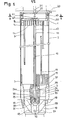
- FIG. 1- represents a view in section through a vertical plane along A of FIG. 2.
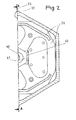
- FIG. 2 represents a half-view in section of the assembly along BB of FIG. 1.
- FIGS. 1 and 2 The assembly shown in FIGS. 1 and 2 comprises, from top to bottom, an upper end piece 1, a housing 2 and a lower end piece 3. These three parts with a hexagonal section are connected together by screws 5.
- the upper end piece 1 has circular openings 8 for fixing the guide tubes 9 connected by welding to the upper end piece 1.
- a guide tube 10 To the central part of the assembly is fixed a guide tube 10, the axis of which coincides with the axis 12 of the assembly and which crosses the latter over its entire height between the two end pieces.
- the upper end piece 1 is also pierced with openings 14 allowing the circulation of water under cooling pressure of the assembly, in the axial direction.
- the lower end piece 3 carries at its upper part a grid 15 for fixing the fissile or fertile fuel rods 16, inside the case, according to a regular network with triangular meshes.
- Each of the rods 16 is held in its position in the network by a spacer constituted by a wire wound helically around its outer surface. In this way, the moderation ratio remains very low and the neutron flux remains in the epithermal range.
- a certain part of fertile material is available, for example uranium depleted in U 235, in certain parts of the assemblies and in certain parts of the core in order to produce fissile material from the fertile material. .
- the lower end piece of tubular shape In its part arranged below the grid 15, the lower end piece of tubular shape, allows the channeling of the pressurized water entering the assembly.
- This lower end piece 3 rests on the lower core support plate 18 in accordance with an opening 19 passing through this plate over its entire thickness.
- the lower plate 18 carries centering pins, not shown, which are engaged, when the assembly is in place on the lower core support plate, as shown in FIG. 1, in openings made in the lower end piece 3. In this way, the assembly is placed in a vertical position so that its axis 12 corresponds to the axis of the opening 19.
- the upper core plate 20 disposed above the assemblies with a clearance d of the order of 5 mm also carries centering pins 21 which engage, when the assembly is in place, in corresponding openings 22 formed in upper end piece 1.
- the device for fixing the assembly to the lower core support plate 18 comprises, in addition to the guide tube 10 passing through the assembly over its entire height between the end pieces, a hooking piece 2 3 fixed on the lower plate of core, an expandable sleeve 24, which is here produced in the form of a flexible blade sleeve, fixed on the end piece / bottom of the assembly, a rod 25 slidably mounted in the guide tube 10 and a sleeve '26 connected to the upper end of the rod 25.
- the hooking piece 23 is constituted by a hooking knob placed at the center of the opening 19 of the plate 18 and connected to the latter by a crosspiece 28 secured to a ring 29, itself fixed by screws 30 on the plate 18, around the opening 19.
- the knob 23 has an opening 31 symmetrical in revolution about the axis 12 of the assembly comprising a conical hooking surface 33 flared downwards.
- the lower end piece 3 carries a central hub 34 by means of a spider 35, the central opening of this hub being of a diameter slightly greater than the diameter of the attachment knob 23.
- the expandable sleeve 24 is fixed inside the means 34 by screwing and locking by means of a pin 37.
- This sleeve 24 comprises two flexible blades 24a and 24b integral with the upper part of the sleeve allowing it to be hooked onto the hub 34.
- the lower part of the blades 24a and 24b constitutes a two-part hooking head comprising conical surfaces which come into contact with the surface 33 formed inside the knob 23, when these blades are in their separated position, as shown in FIG. 1.
- an olive 38 fixed to the lower end of the rod 25 maintains the spacing of the blades 24a and 24b. Maintaining the position of the olive 38 therefore prohibits any vertical movement of the assembly relative to the plate 18, under the effect of the cooling fluid circulating at very high speed.
- the length of the centering pins, not shown, carried by the lower core support plate 18 is such that they carry out a first centering of the assembly relative to the opening 19 and, consequently, relative to the knob 23, before the introduction of the blades 24a and 24b into the opening 31 of the knob 23.
- the hub 34 provides final guidance and further protects the blades 24a and 24b during handling operations. This hub 34 provides protection in service of the blades 24a and 24b against vibrations generated by the flow of the coolant.
- the sliding rod 25 is secured, by virtue of a lock nut 40, to a nut 41 fixed by screwing on the bush 26 at its central part and braked by a brake pad 42.
- the sleeve 26, the rod_25 and the olive 38 therefore form an assembly that is movable in axial translation relative to the assembly.
- a stop 43 fixed on the upper end piece 1 limits the upward movement of this mobile assembly.
- the olive 38 is released from the head of the expandable sleeve so that the flexible blades 24a and 24b can approach each other by elasticity or under the effect of a traction exerted in the vertical direction and from bottom to top on the assembly.
- the assembly For the installation of the assembly in the core, the latter is brought into its position on the lower core plate, the centering pins arranged around the opening 19 coming to engage in the lower end piece 3 and the olive 38 is held in the disengaged position relative to the head of the expandable sleeve 24 so that when the assembly comes to rest on the lower core plate, the sleeve 24 engages in the knob 23 under the effect of the weight of the assembly.
- the assembly consisting of the sleeve 26, the rod 25 and the olive 38 is then lowered into the low position as shown in FIG. 1 to lock the assembly on the plate 18.
- the plate 20 When the loading of the core is finished, the plate 20 is replaced above it, the centering pins 21 being placed in the corresponding openings 22 of the upper ends of the assemblies.
- the locking of the attachment sleeves of the assemblies by downward movement of the movable assembly carrying the olive 38 at its lower part can be achieved at the time when the upper heart plate is placed, if the sleeve 26 is slightly projecting at its upper part relative to the assembly.
- Locking the assembly makes it possible to avoid any displacement thereof in the vertical direction and upwards under the effect of the circulation of pressurized water.
- the olive 38 is released from the head of the sleeve so that the flexible blades 24a and 24b can come closer when the assembly is lifted for its extraction from the heart.
- the central opening of the knob 23 has an extension 45 inside which the olive 38 can be pushed with a very long rod after having removed the brake pad 42 and unscrewing the nut 41, in the event of breakage of the sliding rod 25.
- This makes it possible to unlock the sleeve during a possible rupture of the rod 25 which would then be inoperative and would risk leading to the impossibility of extracting the assembly.
- the fall of the olive 38 in the housing 45 either by gravity or by pushing as described above, allows in all cases of rupture the retraction of the blades 24a and 24b of the sleeve 24.
- the main advantages of the device according to the invention are to obtain a very effective locking of the assembly by an extremely simple operation thanks to a space-saving device disposed in its entirety at the central part of the assembly and the opening of the lower core plate, while presenting the possibility of extracting the assembly in the event of a rupture of the rod providing the control.
- the expandable sleeve can have a number of blades greater than two, that these blades can be articulated and not flexible, that it can be fixed in a different way on the lower end piece of the assembly and that the sleeve 26 can be produced in a form different from the hexagonal shape shown in Figure 2. It is sufficient to ensure effective guidance between this sleeve and the inner surface of the upper end of the assembly.
- the device according to the invention is applicable not only in the case of assemblies with a hexagonal section as used in a sub-moderate reactor but also in the case of hexagonal assemblies used in conventional pressurized water reactors or also in the case of assemblies with square sections as used in the most common type pressurized water nuclear reactors.
- the invention also applies in the case of assemblies of a fast neutron nuclear reactor cooled with liquid sodium.
Landscapes
- Physics & Mathematics (AREA)
- Engineering & Computer Science (AREA)
- Plasma & Fusion (AREA)
- General Engineering & Computer Science (AREA)
- High Energy & Nuclear Physics (AREA)
- Monitoring And Testing Of Nuclear Reactors (AREA)
- Physical Or Chemical Processes And Apparatus (AREA)
- Supports For Pipes And Cables (AREA)
Applications Claiming Priority (2)
| Application Number | Priority Date | Filing Date | Title |
|---|---|---|---|
| FR8122754 | 1981-12-04 | ||
| FR8122754A FR2517867B1 (fr) | 1981-12-04 | 1981-12-04 | Dispositif de fixation d'un assemblage combustible sur la plaque inferieure de support du coeur, dans un reacteur nucleaire |
Publications (2)
| Publication Number | Publication Date |
|---|---|
| EP0081431A1 true EP0081431A1 (de) | 1983-06-15 |
| EP0081431B1 EP0081431B1 (de) | 1985-11-21 |
Family
ID=9264697
Family Applications (1)
| Application Number | Title | Priority Date | Filing Date |
|---|---|---|---|
| EP82402207A Expired EP0081431B1 (de) | 1981-12-04 | 1982-12-03 | Fixierungseinrichtung für ein Brennelementbündel auf der unteren Kernträgerplatte eines Kernreaktors |
Country Status (6)
| Country | Link |
|---|---|
| US (1) | US4623512A (de) |
| EP (1) | EP0081431B1 (de) |
| JP (1) | JPS58103690A (de) |
| KR (1) | KR910001979B1 (de) |
| DE (1) | DE3267624D1 (de) |
| FR (1) | FR2517867B1 (de) |
Cited By (1)
| Publication number | Priority date | Publication date | Assignee | Title |
|---|---|---|---|---|
| US20100282741A1 (en) * | 2007-11-29 | 2010-11-11 | Dow Global Technologies Inc. | Method for controlling and optimizing microwave heating of plastic sheet |
Families Citing this family (4)
| Publication number | Priority date | Publication date | Assignee | Title |
|---|---|---|---|---|
| US4647424A (en) * | 1983-11-16 | 1987-03-03 | Westinghouse Electric Corp. | Fuel assembly unlatching and handling gripper |
| US5029388A (en) * | 1988-12-08 | 1991-07-09 | Westinghouse Electric Corp. | Apparatus and process for sleeving the heat exchanger tubes of nuclear steam generators |
| US8681921B2 (en) * | 2009-03-30 | 2014-03-25 | Ge-Hitachi Nuclear Energy Americas, Llc | System for assembling or disassembling a segmented rod |
| CN115762816A (zh) * | 2022-11-07 | 2023-03-07 | 中国原子能科学研究院 | 反应堆燃料组件 |
Citations (4)
| Publication number | Priority date | Publication date | Assignee | Title |
|---|---|---|---|---|
| GB1159971A (en) * | 1965-07-02 | 1969-07-30 | Babcock & Wilcox Ltd | Improvements in Nuclear Fuel Elements |
| FR2195823A1 (de) * | 1972-08-07 | 1974-03-08 | Atomic Energy Authority Uk | |
| FR2226726A1 (de) * | 1973-04-19 | 1974-11-15 | Siemens Ag | |
| FR2393402A1 (fr) * | 1977-06-03 | 1978-12-29 | Nuclear Power Co Ltd | Cartouche de combustible pour reacteur surregenerateur refroidi par un metal liquide |
Family Cites Families (5)
| Publication number | Priority date | Publication date | Assignee | Title |
|---|---|---|---|---|
| US3635793A (en) * | 1969-10-07 | 1972-01-18 | Atomic Energy Commission | Connector assembly |
| US3814667A (en) * | 1971-05-20 | 1974-06-04 | Combustion Eng | Fuel assembly hold-down device |
| US4038133A (en) * | 1973-04-19 | 1977-07-26 | Siemens Aktiengesellschaft | Nuclear reactor with suspended fuel assemblies having secondary emergency suspensions |
| US4194948A (en) * | 1977-11-14 | 1980-03-25 | General Atomic | Locking support for nuclear fuel assemblies |
| US4381284A (en) * | 1980-12-16 | 1983-04-26 | Westinghouse Electric Corp. | Fuel assembly for a nuclear reactor |
-
1981
- 1981-12-04 FR FR8122754A patent/FR2517867B1/fr not_active Expired
-
1982
- 1982-12-03 JP JP57212604A patent/JPS58103690A/ja active Granted
- 1982-12-03 DE DE8282402207T patent/DE3267624D1/de not_active Expired
- 1982-12-03 EP EP82402207A patent/EP0081431B1/de not_active Expired
- 1982-12-03 KR KR8205425A patent/KR910001979B1/ko not_active Expired
-
1985
- 1985-07-10 US US06/753,344 patent/US4623512A/en not_active Expired - Fee Related
Patent Citations (4)
| Publication number | Priority date | Publication date | Assignee | Title |
|---|---|---|---|---|
| GB1159971A (en) * | 1965-07-02 | 1969-07-30 | Babcock & Wilcox Ltd | Improvements in Nuclear Fuel Elements |
| FR2195823A1 (de) * | 1972-08-07 | 1974-03-08 | Atomic Energy Authority Uk | |
| FR2226726A1 (de) * | 1973-04-19 | 1974-11-15 | Siemens Ag | |
| FR2393402A1 (fr) * | 1977-06-03 | 1978-12-29 | Nuclear Power Co Ltd | Cartouche de combustible pour reacteur surregenerateur refroidi par un metal liquide |
Cited By (1)
| Publication number | Priority date | Publication date | Assignee | Title |
|---|---|---|---|---|
| US20100282741A1 (en) * | 2007-11-29 | 2010-11-11 | Dow Global Technologies Inc. | Method for controlling and optimizing microwave heating of plastic sheet |
Also Published As
| Publication number | Publication date |
|---|---|
| JPS58103690A (ja) | 1983-06-20 |
| KR840003121A (ko) | 1984-08-13 |
| KR910001979B1 (ko) | 1991-03-30 |
| JPH0352595B2 (de) | 1991-08-12 |
| US4623512A (en) | 1986-11-18 |
| DE3267624D1 (en) | 1986-01-02 |
| FR2517867A1 (fr) | 1983-06-10 |
| FR2517867B1 (fr) | 1986-08-22 |
| EP0081431B1 (de) | 1985-11-21 |
Similar Documents
| Publication | Publication Date | Title |
|---|---|---|
| EP3234948B1 (de) | Brennelementbündel für einen sfr kernreaktor, mit einem gehäuse mit lösbar befestigter oberer neutronenabschirmungsvorrichtung | |
| BE897468A (fr) | Procede de remplacement des broches de guidage d'un tube-guide et dispositif correspondant | |
| EP1697945B1 (de) | Brennstoffbaugruppen-endkappe mit einer kühlmittelflussorientierungsdüse und entsprechende baugruppe | |
| EP0456562B1 (de) | Innere Anlage eines Stabbündelführungskernreaktors | |
| EP0123607B1 (de) | Niederhaltungsvorrichtung für Kernreaktor | |
| EP0081431B1 (de) | Fixierungseinrichtung für ein Brennelementbündel auf der unteren Kernträgerplatte eines Kernreaktors | |
| EP0219412B1 (de) | Vorrichtung zum Verriegeln eines Führungsringes auf einer mit einer Öffnung versehenen Platte und Anwendung für ein Führungsrohr eines Kernreaktors | |
| EP0362009B1 (de) | Vorrichtung und Verfahren zum Herausziehen von Blockierhülsen aus Führungsrohren von zerlegbaren Kernreaktorbrennstabbündeln | |
| BE1006028A3 (fr) | Dispositif et procede de devissage et d'extraction a distance d'une vis d'assemblage. | |
| FR2848717A1 (fr) | Procede et dispositif de manutention d'un tube-guide des equipements internes superieurs d'un reacteur nucleaire | |
| EP0344051B1 (de) | Kernbrennelementaufnahme- und Zerlegungszelle | |
| EP0360665B1 (de) | Vorrichtung zum Einsetzen von Führungsrohrblockierhülsen in ein Kopfstück eines zerlegbaren Kernreaktorbrennstabbündels | |
| EP0329541B1 (de) | Obere Kernreaktoreinbauten mit Bündelführungseinrichtung | |
| BE1008994A3 (fr) | Dispositif de pose et d'extraction d'un manchon de blocage d'un tube-guide dans un embout demontable d'un assemblage combustible de reacteur nucleaire. | |
| FR2725298A1 (fr) | Coeur d'un reacteur nucleaire a eau sous pression et embout superieur d'un assemblage de combustible du coeur | |
| BE1007689A3 (fr) | Dispositif d'extraction de pieces ou particules etrangeres dans des assemblages combustibles d'un reacteur nucleaire. | |
| EP0493259B1 (de) | Verfahren und Vorrichtung zur Reparatur eines Abstandhalters in einem Kernreaktorbrennstabbündel | |
| FR2717943A1 (fr) | Procédé de remplacement d'une broche de centrage d'un assemblage combustible et broche de centrage. | |
| EP3479383B1 (de) | Kernreaktor, verfahren für montage und ersatz von thermoelementleitungen, anordnung zur durchführung dieser verfahren | |
| FR2673032A1 (fr) | Procede et dispositif de remplacement d'une broche de centrage d'un assemblage combustible fixee sur la plaque superieure de cóoeur d'un reacteur nucleaire a eau sous pression. | |
| FR3079960A1 (fr) | Reacteur nucleaire et procede de maintenance correspondant | |
| EP0122191B1 (de) | Verfahren zur Herstellung eines Brennstoffelementes und nach diesem Verfahren hergestelltes Element | |
| FR2534732A1 (fr) | Procede et dispositif pour le demantelement de grappes de barres irradiees | |
| FR2846466A1 (fr) | Procede et dispositif de manutention et de separation de la plaque superieure de coeur d'un reacteur nucleaire a eau sous pression, d'un assemblage de combustible | |
| FR2937457A1 (fr) | Procede de recuperation d'au moins un assemblage de combustible reste accroche sous une plaque superieure d'un coeur d'un reacteur nucleaire a eau sous pression |
Legal Events
| Date | Code | Title | Description |
|---|---|---|---|
| PUAI | Public reference made under article 153(3) epc to a published international application that has entered the european phase |
Free format text: ORIGINAL CODE: 0009012 |
|
| AK | Designated contracting states |
Designated state(s): BE DE FR GB IT |
|
| 17P | Request for examination filed |
Effective date: 19830503 |
|
| ITF | It: translation for a ep patent filed | ||
| GRAA | (expected) grant |
Free format text: ORIGINAL CODE: 0009210 |
|
| AK | Designated contracting states |
Designated state(s): BE DE FR GB IT |
|
| REF | Corresponds to: |
Ref document number: 3267624 Country of ref document: DE Date of ref document: 19860102 |
|
| PLBE | No opposition filed within time limit |
Free format text: ORIGINAL CODE: 0009261 |
|
| STAA | Information on the status of an ep patent application or granted ep patent |
Free format text: STATUS: NO OPPOSITION FILED WITHIN TIME LIMIT |
|
| 26N | No opposition filed | ||
| ITTA | It: last paid annual fee | ||
| PGFP | Annual fee paid to national office [announced via postgrant information from national office to epo] |
Ref country code: FR Payment date: 19951124 Year of fee payment: 14 |
|
| PGFP | Annual fee paid to national office [announced via postgrant information from national office to epo] |
Ref country code: GB Payment date: 19951129 Year of fee payment: 14 |
|
| PGFP | Annual fee paid to national office [announced via postgrant information from national office to epo] |
Ref country code: BE Payment date: 19951220 Year of fee payment: 14 |
|
| PGFP | Annual fee paid to national office [announced via postgrant information from national office to epo] |
Ref country code: DE Payment date: 19960228 Year of fee payment: 14 |
|
| PG25 | Lapsed in a contracting state [announced via postgrant information from national office to epo] |
Ref country code: GB Effective date: 19961203 |
|
| PG25 | Lapsed in a contracting state [announced via postgrant information from national office to epo] |
Ref country code: BE Effective date: 19961231 |
|
| BERE | Be: lapsed |
Owner name: FRAMATOME ET CIE Effective date: 19961231 |
|
| GBPC | Gb: european patent ceased through non-payment of renewal fee |
Effective date: 19961203 |
|
| PG25 | Lapsed in a contracting state [announced via postgrant information from national office to epo] |
Ref country code: FR Effective date: 19970829 |
|
| PG25 | Lapsed in a contracting state [announced via postgrant information from national office to epo] |
Ref country code: DE Effective date: 19970902 |
|
| REG | Reference to a national code |
Ref country code: FR Ref legal event code: ST |