EP0081631A2 - Appareil de traitement de bande passant d'une bobine à l'autre - Google Patents
Appareil de traitement de bande passant d'une bobine à l'autre Download PDFInfo
- Publication number
- EP0081631A2 EP0081631A2 EP82108071A EP82108071A EP0081631A2 EP 0081631 A2 EP0081631 A2 EP 0081631A2 EP 82108071 A EP82108071 A EP 82108071A EP 82108071 A EP82108071 A EP 82108071A EP 0081631 A2 EP0081631 A2 EP 0081631A2
- Authority
- EP
- European Patent Office
- Prior art keywords
- web
- air
- chamber
- reel
- bight
- Prior art date
- Legal status (The legal status is an assumption and is not a legal conclusion. Google has not performed a legal analysis and makes no representation as to the accuracy of the status listed.)
- Granted
Links
- 230000033228 biological regulation Effects 0.000 claims description 4
- 230000008859 change Effects 0.000 claims description 4
- 230000001105 regulatory effect Effects 0.000 claims description 4
- 238000004891 communication Methods 0.000 claims description 3
- 239000012530 fluid Substances 0.000 claims description 3
- 230000033001 locomotion Effects 0.000 claims description 3
- 238000007789 sealing Methods 0.000 claims description 3
- 230000000694 effects Effects 0.000 claims description 2
- 238000012546 transfer Methods 0.000 claims description 2
- 239000000872 buffer Substances 0.000 description 9
- 230000002463 transducing effect Effects 0.000 description 9
- 230000001133 acceleration Effects 0.000 description 4
- 230000007246 mechanism Effects 0.000 description 4
- 238000000034 method Methods 0.000 description 4
- 230000003247 decreasing effect Effects 0.000 description 3
- 230000003139 buffering effect Effects 0.000 description 2
- 230000007423 decrease Effects 0.000 description 2
- 238000006073 displacement reaction Methods 0.000 description 2
- 230000006872 improvement Effects 0.000 description 2
- 238000012545 processing Methods 0.000 description 2
- 238000004904 shortening Methods 0.000 description 2
- 238000013459 approach Methods 0.000 description 1
- 239000011248 coating agent Substances 0.000 description 1
- 238000000576 coating method Methods 0.000 description 1
- 230000001276 controlling effect Effects 0.000 description 1
- 230000008569 process Effects 0.000 description 1
- 230000002441 reversible effect Effects 0.000 description 1
- 230000000087 stabilizing effect Effects 0.000 description 1
- 239000000758 substrate Substances 0.000 description 1
Images

Classifications
-
- G—PHYSICS
- G11—INFORMATION STORAGE
- G11B—INFORMATION STORAGE BASED ON RELATIVE MOVEMENT BETWEEN RECORD CARRIER AND TRANSDUCER
- G11B15/00—Driving, starting or stopping record carriers of filamentary or web form; Driving both such record carriers and heads; Guiding such record carriers or containers therefor; Control thereof; Control of operating function
- G11B15/60—Guiding record carrier
- G11B15/66—Threading; Loading; Automatic self-loading
- G11B15/67—Threading; Loading; Automatic self-loading by extracting end of record carrier from container or spool
-
- G—PHYSICS
- G11—INFORMATION STORAGE
- G11B—INFORMATION STORAGE BASED ON RELATIVE MOVEMENT BETWEEN RECORD CARRIER AND TRANSDUCER
- G11B15/00—Driving, starting or stopping record carriers of filamentary or web form; Driving both such record carriers and heads; Guiding such record carriers or containers therefor; Control thereof; Control of operating function
- G11B15/56—Driving, starting or stopping record carriers of filamentary or web form; Driving both such record carriers and heads; Guiding such record carriers or containers therefor; Control thereof; Control of operating function the record carrier having reserve loop, e.g. to minimise inertia during acceleration measuring or control in connection therewith
- G11B15/58—Driving, starting or stopping record carriers of filamentary or web form; Driving both such record carriers and heads; Guiding such record carriers or containers therefor; Control thereof; Control of operating function the record carrier having reserve loop, e.g. to minimise inertia during acceleration measuring or control in connection therewith with vacuum column
Definitions
- the present invention relates to reel-to-reel web handling apparatus.
- Webs in the form of magnetically-coated tapes have been used for several years for recording digital data received from data processing equipments of all types. Additionally, such webs have been used for audio and video applications as well. For data processing applications, it is desirable that access to data recording areas on the web occur rapidly.
- so-called vacuum columns such as disclosed in GB-A-733807, US-A-3,057,568 and US-A-3,057,569, may be employed to provide a buffer between web or tape-containing reels and a transducer or work station. The arrangement is such that a capstan rapidly accelerates the web to provide the rapid access with the vacuum columns providing a low inertial length of web for permitting rapid acceleration and the resulting rapid access.
- the vacuum columns decouple the work station from the reel of tape such that a relatively short length of the web can be accelerated while the reel is being rotationally accelerated.
- the bight of the web formed in the vacuum column varies in length as the reel inertia is compensated for.
- the length of the bight in the vacuum column varies dramatically.
- An improvement over those vacuum columns is disclosed in GB-A-847821 and US-A-3,112,473, in which the walls of the vacuum columns are tapered so that as the bight becomes longer it also becomes narrower which decreases the pull on the web.
- GB-A-12777111 and US-A-3,645,470 show an air passageway extending between two side-by-side vacuum columns to serve as a clamp such that when a web is loaded into the vacuum columns it will load into both columns.
- the clamp limits the slip of the web over a capstan so that the web enters both vacuum columns.
- This control limits the transport of the web between adjacent vacuum columns during the loading process.
- a work station or transducer station is integral to one of the vacuum columns.
- US-A-3,986,651 shows a symmetrical web transport arrangement in which concave vacuum assisted guides are used to guide the web past a work or transducer station with vacuum columns stabilizing the flow of tape, i.e. decoupling the capstan from the web-containing reels.
- US-A-3,281,040 also shows a vacuum assisted guide in which slots along the guides permit air flow for controlling the web within the vacuum chamber guide.
- US-A-4,218,026 shows a vacuum arrangement with an adjustable side, ostensibly for taking various widths of webs.
- US-A-3,266,691 shows a series of tapered vacuum loop boxes for preventing breakage of the web during rapid acceleration-deceleration.
- Tape tension control is disclosed in IBM Technical Disclosure Bulletin, February, 1975, page 2564, in which a so-called soft vacuum pocket redistributes tension uniformly across the tape.
- the soft vacuum pocket is bracketed in the tape path by a pair of air bearings.
- the tape tension redistribution device eliminates non-uniform stresses or tensions in the tape, which, among other things, accommodates skewing caused by misaligned reels. Such skewing appears in the tape as a curvature between the two misaligned reels.
- a high performance reel-to-reel web transport such as used in a reel-to-reel magnetic tape recorder
- uniform tension is applied to the web during rapid acceleration-deceleration.
- Standing waves can be induced into the web such that there are differing tape tensions along the tape path between the reels.
- the angle of approach from the reel to the web transport path changes. This change in angulation can affect the length of web disposed between the reel and a work station and disposed between the two reels in the reel-to-reel transport.
- the web may have a lateral curvature induced from being stored on a reel.
- reel-to-reel web handling apparatus having tension control means tending to maintain a uniform tension in a web extending and transportable between two reels, means to change the speed of web transport between reels which may introduce perturbations in the tension, a work station disposed between the two reels, at which work is performable on the web, is characterised by web bight forming means disposed between the work station and one of the reels for receiving the web to form a bight therein and bight regulation means in the bight forming means to maintain a relatively constant bight during web stoppage and a bight variable in accordance with tension changes during web motion to control the length of web between the work station and the one reel to a relatively constant length.
- the invention extends to a web-handling vacuum chamber structure having an open web-receiving portion and an air-exhaust chamber, with a pair of parallel and facing side walls spaced apart so as to closely receive a web through in a substantial air sealing relation, whereby air exhausted from the air-exhaust chamber tends to pull any web in the web-receiving portion into the chamber, and the chamber includes a section with a greater spacing than the spacing between the side walls, so that as the web moves from the web-receiving portion into the chamber the air seal is broken allowing air to flow past the web, thus reducing the tendency to pull, whereby the web is maintained in a relatively constant position in the structure for a given web tension.
- the invention also lies in a method of operating a reel-to-reel magnetic tape recorder having a tape path extending between a pair of tape-containing reels having a tape extending therebetween, and means for selectively rotating said reels to transport tape therebetween at a substantially constant tension, but subject to perturbations in tension, a transducing station disposed adjacent said tape path means to be in transducing relationship to said tape and disposed a given distance from a one of said tape reels, comprising the steps of forming a dimple in the tape intermediate the transducing station and the one tape reel, when the tension increases tending to shorten the length of tape between the transducing station and the one tape reel, applying greater force on the tape in the formed dimple which tends to maintain the dimple to prevent the tape length from shortening, and when the tension decreases tending to lengthen the length of tape between the transducing station and the one tape reel, reducing the force on the tape in accordance with the depth of the dimple so that the tape length tends not to increase due to
- the invention is a magnetic tape recorder having a machine reel for receiving magnetic tape and a machine reel for supplying magnetic tape, means for selectively transporting tape along a path between the reels at a relatively constant tension, transducer in juxtaposition which the tape path for being in a transducing relationship with a magnetic tape being transported between the reels, means interposed between the supply reel and the transducer to receive the magnetic tape and including tape length adjusting means responsive to variations in tension tending to increase tape length between the reel and the transducer for increased tension and tending to reduce the tape length between the reel and the transducer for decreased tension, so that changes in tension do not change the length of tape between the supply reel and the transducer, whereby a stabilized recording relationship is maintained between the transducer means and the magnetic tape being transported between the reels.
- a reel-to-reel web handler having uniform tension control means includes a web bight forming means disposed between a work station a web-containing reel such that a controlled bight is formed between the work station and one of the reels.
- the bight is controlled to maintain a relatively constant length of web between the work station and the one reel regardless of angulation changes and accommodates lateral curvature of the web before the web reaches the work station as well as accommodating uniform tension variations for eliminating tension waves from the web before the web arrives at the work station.
- the bight-forming means is a vacuum chamber having a web receiving portion which receives the web in an air sealing relationship with an air exhaust portion having a cavity with a greater wall-to-wall dimension than the web receiving portion such that as the web enters the air exhaust portion, the pull on the web is controllably reduced for regulating the bight of the web in accordance with the greater wall-to-wall dimension and air exhaust flow.
- This control accommodates perturbations in uniform tension to establish a substantially constant length of web between a work station and a web containing reel.
- the invention includes method and apparatus achieving the above-stated functions.
- a cartridge 11, containing a supply reel 12 of magnetically coated web 15, is replaceably installed at one corner.
- the free end of the web 15 is automatically transported by the recorder 10 over a transport path to a machine take-up reel 13.
- the web 15 is taken off reel 12 passed through a tape controller 16, which embodies the present invention and is later described with respect to Figures 2, 3 and 4. From the controller 16, the web 15 passes around an airbearing arcuate guide 17 to pass over a transducer or work station 14. Thence, the web 15 passes around a second airbearing arcuate guide 18, and around a tension idler wheel 19 to the machine reel 13.
- Direction of tape transport over the just described path is reversible.
- the tension idler wheel 19 is supported by a tension transducer 20 for indicating via an electrical connection 22 to electronic circuits 21 the sensed tension of web 15 as it is being transported or being held.
- Electronic circuits 21 respond to the tension indication supplied over connection 22 to control the rotation of reels 12 and 13 in a manner such that positive pressure is exerted by web 15 onto the web-facing surface of the transducer at station 14 for ensuring a good so-called recording platform, i.e. ensures a good exchange of signals between the magnetic coating on web tape 15 and the transducer at station 14.
- Circuits 21 additionally are connected to a using unit (not shown) via a bus 23.
- the using unit supplies commands to electronic circuits 21 which include commands to move the web 15 between reels 12 and 13 as well as to transfer signals between the magnetic record area on web 15 and the using unit, by recording signals via bus 25 and transducer 14, or receive signals from transducer 14 via bus 25.
- Electronic circuits 21 also include the usual servo-control circuits which control the speed of transport of the web 15. Associated with each of the reels 12 and 13 is a motor (not shown) controlled by electrical signals supplied by electronic circuits 21 over electrical connections 26 and 27, which co-ordinate the rotation of reels 12 and 13, respectively, using known reel-to-reel control techniques. Tachometer wheels 30 and 32, on reels 12 and 13, respectively, provide rotational speed-indicating signals over lines 31 and 33, respectively, to electronic circuits 21 for implementing the servo control. Additionally, the signals from tachometer wheels 30, 32 indicate web displacement. In particular, tachometer wheel 30 is used by electronic circuits 21 to evaluate the amount of web 15 unwound from reel 12. Such displacement indication is used in combination with addresses recorded on web 15 for addressing record areas on web 15.
- Air supply mechanism 37 supplies air under pressure through conduit 40 to arcuate air bearing guides 17 and 18 and to air bearings, described later, in web controller 16. Air supply mechanism 37 also exhausts air through conduit 41 from controller 16 to provide a so-called vacuum chamber used in connection with the regulation of web 15 as it is transported between reel 12 and transducer or work station 14. Air supply mechanism 37 provides a constant air flow through conduit 41 which results in a pulling force on web 15 greater than the tension provided to web 15 by the co-ordinated control of reels 12 and 13. Such greater force is used, as described later, to achieve the functions of the present invention. The air flow through conduit 40 is also at a constant pressure.
- Controller 16 provides several regulating controls for maintaining a substantially constant length of web 15 as well as ensuring a relatively flat surface on web 15 as it passes transducer or work station 14.
- Controller 16 receives web 15 from reel 12 at leading edge 50 of a web guiding portion.
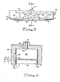
- the web guiding portion has a convex web receiving surface beginning at leading edge 50 and including an air bearing area 51 having a plurality of air apertures 52 receiving air from plenum 53 (Fig.3).
- Plenum 53 is in fluid communication with air pressure conduit 40 via air passageway 54.
- the web guiding portion has a second convex web receiving surface spaced from the surface including the area 51, ending at trailing edge 78 and including an air bearing area 75 having a plurality of air apertures receiving air from plenum 76 which is in fluid communication with air pressure conduit 40 via air passageway 77.
- the convex surface including air bearing 51 has tape side guides 56 and 57 for guiding web 15 centrally over the air bearing area 51, which guides diverge slightly beyond the leading edge 50 and the trailing edge 78 of the web guiding portion.
- the side guides 56 and 57 are mounted in a channel shaped structure 60. Between the convex web receiving surfaces, the web 15 extends across the open side of a vacuum chamber 63 which provides length regulation of tape 15, as will become apparent.
- the chamber 63 is connected by a passage 64 to the air exhaust conduit 41. With the web stretched flat between the air bearing areas 51 and 75, it lies in an outer portion 61 of the chamber 63 between the guides 56 and 57. The edges of the web are sufficiently close to the guides 56 and 57 to form an air seal so that air exhausted through conduit 41 and passage 64 from the chamber 63 provides a maximum force on the web. This overcomes the tension in the web 15, so that the web 15 is pulled through the outer portion 61 into the air exhaust chamber 63.
- An elongated groove 62 is formed in a side wall of the channel shaped structure 60.
- the groove 62 communicates with the chamber 63 through an elongated slot in the guide 57.
- the groove and slot have a shoulder 73 adjacent the outer portion 61, which shoulder extends transverse to the guide 57 to provide a sharp increase in the width of the chamber 63.
- the groove 62 breaks the air seal to allow air flow past the web 15 from the outer portion 61 through air exhaust chamber 63, and passage 64 to the air exhaust conduit 41.
- Such air flow regulates the web to a position of equilibrium with the tension on web 15 provided through the control of reels 12 and 13 by electronic circuits 21.
- the web is drawn into an approximate catenary between the areas 51 and 75 and the central portion of relatively shallow bight so formed has a nominal web position 70 which occurs during constant-speed web transport or when web 15 is stationary.
- the uniform tension exerted on web 15 is subject to perturbations which are accommodated by controller 16 to keep a constant length of web between supply reel 12 and transducer 14.
- controller 16 controls the uniform tension exerted on web 15 to keep a constant length of web between supply reel 12 and transducer 14.
- the upper limit position 71 is determined by the shoulder 73 of the groove 62. At shoulder 73, the air pull on web 15 exceeds the web tension preventing further shortening of the bight.
- reel 12 will rotate to allow more web 15 to keep the web length as represented by lines 42 and 43 substantially constant by accommodating variations in web tension.
- tension on web 15 is reduced, then the bight in air exhaust chambers 63 tends to increase up to an inner level position 72 to accommodate the reduced web tension.
- controller 16 removes the flutter from the web, so that a reliable recording platform is maintained at transducing station 14. Variations in web 15 transport behaviour as it leaves reel 12 are accommodated in controller 16 so that as the web 15 leaves controller 16 the longitudinal edges of the web 15 are in line and the web equalized in tension. Accordingly, it is desirable to place controller 16 relatively close to the removable cartridge 11 so that web transport is consistent over as great a portion of the transport path as possible.
- the relatively shallow vacuum chamber 63 and the bypass groove 62 provide effective decoupling of the transducing station 14 from web transport perturbations that may occur as web 15 leaves removable supply reel 12.
Landscapes
- Advancing Webs (AREA)
- Controlling Rewinding, Feeding, Winding, Or Abnormalities Of Webs (AREA)
- Registering, Tensioning, Guiding Webs, And Rollers Therefor (AREA)
Applications Claiming Priority (2)
| Application Number | Priority Date | Filing Date | Title |
|---|---|---|---|
| US06/332,261 US4406425A (en) | 1981-12-18 | 1981-12-18 | Method and apparatus for regulating webs transported in a reel-to-reel web handler |
| US332261 | 1989-03-31 |
Publications (3)
| Publication Number | Publication Date |
|---|---|
| EP0081631A2 true EP0081631A2 (fr) | 1983-06-22 |
| EP0081631A3 EP0081631A3 (en) | 1984-03-28 |
| EP0081631B1 EP0081631B1 (fr) | 1986-08-27 |
Family
ID=23297453
Family Applications (1)
| Application Number | Title | Priority Date | Filing Date |
|---|---|---|---|
| EP82108071A Expired EP0081631B1 (fr) | 1981-12-18 | 1982-09-02 | Appareil de traitement de bande passant d'une bobine à l'autre |
Country Status (4)
| Country | Link |
|---|---|
| US (1) | US4406425A (fr) |
| EP (1) | EP0081631B1 (fr) |
| JP (1) | JPS58108051A (fr) |
| DE (1) | DE3272890D1 (fr) |
Families Citing this family (7)
| Publication number | Priority date | Publication date | Assignee | Title |
|---|---|---|---|---|
| JP2793410B2 (ja) * | 1991-04-22 | 1998-09-03 | インターナショナル・ビジネス・マシーンズ・コーポレイション | ウェブ駆動装置及びテープ駆動装置 |
| US5289331A (en) * | 1991-06-13 | 1994-02-22 | International Business Machines Corporation | Constrained pivot guide post |
| JP2516301B2 (ja) * | 1991-06-13 | 1996-07-24 | インターナショナル・ビジネス・マシーンズ・コーポレイション | テ―プ駆動装置 |
| US5245485A (en) * | 1991-08-30 | 1993-09-14 | International Business Machines Corporation | Multiple tape thickness, multiple recording format tape drive systems |
| US5432653A (en) * | 1993-06-22 | 1995-07-11 | Minnesota Mining And Manufacturing Company | Loop-shaped pneumatic drive |
| US5485325A (en) * | 1994-04-04 | 1996-01-16 | Minnesota Mining And Manufacturing Company | Magazine storage system for recording strips |
| US20100213305A1 (en) * | 2009-02-26 | 2010-08-26 | Andritz Inc. | Apparatus and method for stabilizing a moving web |
Family Cites Families (7)
| Publication number | Priority date | Publication date | Assignee | Title |
|---|---|---|---|---|
| US3074661A (en) * | 1957-11-22 | 1963-01-22 | Ampex | Magnetic tape machine |
| JPS4120271Y1 (fr) * | 1964-02-28 | 1966-09-26 | ||
| DE1250710B (fr) * | 1964-08-10 | |||
| US3499614A (en) * | 1967-12-26 | 1970-03-10 | Ibm | Automatic web buffering means |
| US3890641A (en) * | 1972-09-01 | 1975-06-17 | Int Video Corp | Helical scan magnetic tape transport system including vacuum column tension control and helical scanner air bearing |
| US3866855A (en) * | 1972-10-24 | 1975-02-18 | Wangco Inc | Tape tension and velocity control system |
| JPS4984616A (fr) * | 1972-12-19 | 1974-08-14 |
-
1981
- 1981-12-18 US US06/332,261 patent/US4406425A/en not_active Expired - Lifetime
-
1982
- 1982-09-02 DE DE8282108071T patent/DE3272890D1/de not_active Expired
- 1982-09-02 EP EP82108071A patent/EP0081631B1/fr not_active Expired
- 1982-09-16 JP JP57159718A patent/JPS58108051A/ja active Granted
Also Published As
| Publication number | Publication date |
|---|---|
| JPS58108051A (ja) | 1983-06-28 |
| DE3272890D1 (en) | 1986-10-02 |
| JPH0226304B2 (fr) | 1990-06-08 |
| US4406425A (en) | 1983-09-27 |
| EP0081631A3 (en) | 1984-03-28 |
| EP0081631B1 (fr) | 1986-08-27 |
Similar Documents
| Publication | Publication Date | Title |
|---|---|---|
| US3781490A (en) | Web tension and speed control in a reel-to-reel web transport | |
| US3189291A (en) | Tape handling machine | |
| EP0081631B1 (fr) | Appareil de traitement de bande passant d'une bobine à l'autre | |
| JPH0660491A (ja) | テープ走行系制御装置 | |
| US2980355A (en) | Tape-feeding apparatus | |
| US2968702A (en) | Transport means for a magnet recorder-reproducer | |
| EP0556132A1 (fr) | Méthode et dispositif pour variablement régler la vitesse d'un rouleau entraîneur répétiteur | |
| WO1988007746A1 (fr) | Appareil de guidage et d'exploration helicoidale de bande magnetique | |
| US4316568A (en) | Methods and apparatus for guiding tape | |
| US4772969A (en) | "Expandable loop" method of and apparatus for automatically threading a web material | |
| EP0893795B1 (fr) | Dispositif empêchant l'entrainement d'air | |
| US3297221A (en) | Transport mechanism for flexible materials | |
| US3826446A (en) | Pneumatic tape rewind system | |
| US3937421A (en) | Asynchronous high-speed pneumatic film transport mechanism | |
| JPS5948460B2 (ja) | テ−プ移送装置 | |
| US3341070A (en) | Record member guide device | |
| EP0008920B1 (fr) | Mécanisme de transport de bande magnétique | |
| EP0439366B1 (fr) | Dispositif de réglage de tension de bande | |
| US3512692A (en) | Tape handling apparatus | |
| JPS62269841A (ja) | 画像記録装置 | |
| US4749145A (en) | In-cassette tape tensioning apparatus | |
| US3384317A (en) | Tape handler apparatus | |
| JPH03122862A (ja) | テープ移送装置 | |
| JPH05258419A (ja) | ロータリーヘッドテープ送りにおけるシングルリールカートリッジから磁気テープを装着する装置 | |
| JP2000302304A (ja) | テープ搬送装置及び方法 |
Legal Events
| Date | Code | Title | Description |
|---|---|---|---|
| PUAI | Public reference made under article 153(3) epc to a published international application that has entered the european phase |
Free format text: ORIGINAL CODE: 0009012 |
|
| AK | Designated contracting states |
Designated state(s): DE FR GB |
|
| 17P | Request for examination filed |
Effective date: 19831021 |
|
| PUAL | Search report despatched |
Free format text: ORIGINAL CODE: 0009013 |
|
| AK | Designated contracting states |
Designated state(s): DE FR GB |
|
| GRAA | (expected) grant |
Free format text: ORIGINAL CODE: 0009210 |
|
| AK | Designated contracting states |
Kind code of ref document: B1 Designated state(s): DE FR GB |
|
| REF | Corresponds to: |
Ref document number: 3272890 Country of ref document: DE Date of ref document: 19861002 |
|
| ET | Fr: translation filed | ||
| PLBE | No opposition filed within time limit |
Free format text: ORIGINAL CODE: 0009261 |
|
| STAA | Information on the status of an ep patent application or granted ep patent |
Free format text: STATUS: NO OPPOSITION FILED WITHIN TIME LIMIT |
|
| 26N | No opposition filed | ||
| PGFP | Annual fee paid to national office [announced via postgrant information from national office to epo] |
Ref country code: GB Payment date: 19950822 Year of fee payment: 14 |
|
| PGFP | Annual fee paid to national office [announced via postgrant information from national office to epo] |
Ref country code: FR Payment date: 19950911 Year of fee payment: 14 |
|
| PGFP | Annual fee paid to national office [announced via postgrant information from national office to epo] |
Ref country code: DE Payment date: 19950921 Year of fee payment: 14 |
|
| PG25 | Lapsed in a contracting state [announced via postgrant information from national office to epo] |
Ref country code: GB Effective date: 19960902 |
|
| PG25 | Lapsed in a contracting state [announced via postgrant information from national office to epo] |
Ref country code: FR Effective date: 19960930 |
|
| GBPC | Gb: european patent ceased through non-payment of renewal fee |
Effective date: 19960902 |
|
| PG25 | Lapsed in a contracting state [announced via postgrant information from national office to epo] |
Ref country code: DE Effective date: 19970603 |
|
| REG | Reference to a national code |
Ref country code: FR Ref legal event code: ST |
|
| REG | Reference to a national code |
Ref country code: FR Ref legal event code: ST |