EP0081720A2 - Petite machine électrique, en particulier petit moteur - Google Patents
Petite machine électrique, en particulier petit moteur Download PDFInfo
- Publication number
- EP0081720A2 EP0081720A2 EP19820110928 EP82110928A EP0081720A2 EP 0081720 A2 EP0081720 A2 EP 0081720A2 EP 19820110928 EP19820110928 EP 19820110928 EP 82110928 A EP82110928 A EP 82110928A EP 0081720 A2 EP0081720 A2 EP 0081720A2
- Authority
- EP
- European Patent Office
- Prior art keywords
- bearing
- electrical machine
- small electrical
- armature shaft
- machine according
- Prior art date
- Legal status (The legal status is an assumption and is not a legal conclusion. Google has not performed a legal analysis and makes no representation as to the accuracy of the status listed.)
- Withdrawn
Links
- 239000002184 metal Substances 0.000 claims description 4
- 230000006978 adaptation Effects 0.000 description 1
- 230000005540 biological transmission Effects 0.000 description 1
- 238000011161 development Methods 0.000 description 1
- 230000018109 developmental process Effects 0.000 description 1
- 230000013011 mating Effects 0.000 description 1
- 238000005096 rolling process Methods 0.000 description 1
Images

Classifications
-
- H—ELECTRICITY
- H02—GENERATION; CONVERSION OR DISTRIBUTION OF ELECTRIC POWER
- H02K—DYNAMO-ELECTRIC MACHINES
- H02K7/00—Arrangements for handling mechanical energy structurally associated with dynamo-electric machines, e.g. structural association with mechanical driving motors or auxiliary dynamo-electric machines
- H02K7/08—Structural association with bearings
- H02K7/083—Structural association with bearings radially supporting the rotary shaft at both ends of the rotor
-
- H—ELECTRICITY
- H02—GENERATION; CONVERSION OR DISTRIBUTION OF ELECTRIC POWER
- H02K—DYNAMO-ELECTRIC MACHINES
- H02K5/00—Casings; Enclosures; Supports
- H02K5/04—Casings or enclosures characterised by the shape, form or construction thereof
- H02K5/16—Means for supporting bearings, e.g. insulating supports or means for fitting bearings in the bearing-shields
- H02K5/161—Means for supporting bearings, e.g. insulating supports or means for fitting bearings in the bearing-shields radially supporting the rotary shaft at both ends of the rotor
-
- F—MECHANICAL ENGINEERING; LIGHTING; HEATING; WEAPONS; BLASTING
- F16—ENGINEERING ELEMENTS AND UNITS; GENERAL MEASURES FOR PRODUCING AND MAINTAINING EFFECTIVE FUNCTIONING OF MACHINES OR INSTALLATIONS; THERMAL INSULATION IN GENERAL
- F16H—GEARING
- F16H57/00—General details of gearing
- F16H57/02—Gearboxes; Mounting gearing therein
- F16H57/021—Shaft support structures, e.g. partition walls, bearing eyes, casing walls or covers with bearings
- F16H2057/0213—Support of worm gear shafts
Definitions
- the invention is based on a small electric motor according to the preamble of the main claim.
- a small electric motor is already known, in which an adapter ring is adapted to the yoke ring, on which in turn an assembly can then be placed.
- a flawless adaptation to the armature shaft of the drive motor can only be achieved if the fit on the yoke ring is centered on the armature shaft.
- this is not usually the case with small electrical machines, because the return ring is bent from a sheet metal strip for cost reasons alone and is therefore not perfectly circular. In small machines of this type, the return ring therefore requires rework to create a receiving seat for the adapter ring that is central to the armature shaft.
- the small machine according to the invention with the characterizing features of the main claim has the advantage that it is necessarily absolutely centric to the armature shaft Ging bearing element is used for collecting and centering an assembly to be arranged on the small machine, for example a transmission. Reworking the return ring can therefore be omitted.
- Another advantage is that the adapter ring available in the prior art and the associated assembly work are also dispensed with.
- FIG. 1 shows a longitudinal section through a small electric motor
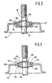
- FIG. 2 shows a partial section through a differently designed small electric motor
- FIG. 3 shows a third embodiment of a small electric motor in partial section.
- An electric small motor shown in section in FIG. 1 is used, for example, to drive an adjusting device, such as is used in the motor vehicle for adjusting a sunroof, etc.
- the drive motor 10 has a structure and a dimensioning that identifies it in technical terms as a so-called small motor.
- the drive motor 10 is equipped with an annular, magnetic yoke 12, the ge from a sheet metal strip has been rolled. The joint on the return ring is latched in a manner known per se.
- the yoke ring 12 is provided on its two end faces 14 and 16, each with a bow-shaped bearing bracket 18 and 20.
- the bearing brackets 18 and 20 are also each bent from a sheet metal strip and attached to the end faces 14 and 16 of the yoke ring 12.
- the yoke ring 12 forms, together with the bearing supports 18 and 20, the housing of the electric drive motor 10. Permanent magnets 22 which generate the magnetic field are arranged on the yoke ring 12.
- a shaft bearing 24 and 26 are each held on the bearing supports 18 and 20.
- the shaft bearing 24 is formed by a roller bearing, the inner ring 28 of which sits on an end section 30 of an armature shaft 32 which carries the motor armature 34 belonging to the drive motor 10.
- the end section 30 of the armature shaft 32 penetrates the bearing bracket 18 and thus protrudes from the motor housing 12, 18, 20.
- the shaft bearing 26 consists of a spherical cap 35 designed as a plain bearing, which is adjustable in a pan-shaped bulge 37 of the bearing bracket 20.
- the roller bearing 24 is arranged in a recess 36 which is open to the outside and has been introduced into the bearing carrier 18 by non-cutting deformation.
- the depression 36 is dimensioned such that the outer ring 38 of the rolling bearing 24 dips into the depression 36 and sits in the latter.
- the depth of the depression 36 is dimensioned such that the roller bearing 24 protrudes beyond the housing 12, 18, 20 with a section 40 extending in the direction of the axis of the armature shaft 32.
- the end section 30 of the armature shaft 32 and the shaft bearing 24 are arranged on the same of the motor housing 12, 18, 20.
- the depression 36 thus forms a receptacle for the shaft bearing 24.
- the section 40 of the shaft bearing 24 protruding from the depression 36 serves with its outer surface 42 as a centering fit for an assembly to be fastened to the drive motor 10. which can be formed, for example, by a reduction gear.
- FIGS. 2 and 3 essentially correspond to the embodiment just described. For this reason, identical parts have been given the same reference number as in the exemplary embodiment according to FIG. 1.
- the shaft bearing 124 is designed as a spherical bearing for the armature shaft 32 or for its end section 30.
- the spherical bearing 124 is constructed from two halves 126 and 128.
- the outer half 126 forms the bearing socket for the second bearing half 128 designed as a bearing cap.
- the bearing half 126 sits in the depression 36 of the bearing bracket 118 and projects with a portion 140 from the depression 36 in the direction of the armature shaft axis beyond the housing.
- the outer wall surface 142 of the bearing half 126 forms a snug fit for a counter-fit, which is arranged on the assembly to be connected to the drive motor 110.
- the embodiment according to FIG. 3 also has a shaft bearing 224 which is designed as a spherical bearing.
- the bearing bracket 218 is provided with an opening 236, which serves as a receptacle for the outer bearing half 226 of the spherical bearing 224 designed as a bearing socket.
- the bearing half 226 is made of a plastic and is injected into the opening 236 in the bearing bracket 226.
- the inside and outer edge regions 228, 230 of the opening 236 are gripped by holder shoulders 232 and 234 of the bearing half 226.
- the outer wall surface 242 of the outer bearing half 226 - in the region of the section 240 extending beyond the motor housing - serves as a snug fit for a mating fit on the assembly to be connected to the drive motor 210.
- the outer wall or lateral surfaces 42, 142, 242 of the shaft bearings 24, 124, 224 are designed so that they meet all requirements that are placed on such fitting seats.
Landscapes
- Engineering & Computer Science (AREA)
- Power Engineering (AREA)
- Motor Or Generator Frames (AREA)
- Support Of The Bearing (AREA)
Applications Claiming Priority (2)
| Application Number | Priority Date | Filing Date | Title |
|---|---|---|---|
| DE3149106 | 1981-12-11 | ||
| DE19813149106 DE3149106A1 (de) | 1981-12-11 | 1981-12-11 | Elektrische kleinmaschine, insbesondere kleinmotor |
Publications (1)
| Publication Number | Publication Date |
|---|---|
| EP0081720A2 true EP0081720A2 (fr) | 1983-06-22 |
Family
ID=6148486
Family Applications (1)
| Application Number | Title | Priority Date | Filing Date |
|---|---|---|---|
| EP19820110928 Withdrawn EP0081720A2 (fr) | 1981-12-11 | 1982-11-26 | Petite machine électrique, en particulier petit moteur |
Country Status (2)
| Country | Link |
|---|---|
| EP (1) | EP0081720A2 (fr) |
| DE (1) | DE3149106A1 (fr) |
Cited By (2)
| Publication number | Priority date | Publication date | Assignee | Title |
|---|---|---|---|---|
| US4853489A (en) * | 1982-06-03 | 1989-08-01 | Gonzenbach Hans U | Selective chlorination of para-tertiary-butytoluene |
| EP0524552A1 (fr) * | 1991-07-22 | 1993-01-27 | Whirlpool Europe B.V. | Moteur compresseur hermétique avce un dispositif de retenue pour la partie basse de l'arbre d'entraînement |
Families Citing this family (3)
| Publication number | Priority date | Publication date | Assignee | Title |
|---|---|---|---|---|
| DE3744488A1 (de) * | 1987-12-30 | 1989-07-20 | Kress Elektrik Gmbh & Co | Elektrischer universalmotor |
| DE3923421A1 (de) * | 1989-07-15 | 1991-01-24 | Kress Elektrik Gmbh & Co | Elektrischer universalmotor |
| DE4125491A1 (de) * | 1991-08-01 | 1993-02-04 | Swf Auto Electric Gmbh | Schnecke mit angeformtem lagerzapfen, insbes. fuer eine scheibenwischanlage |
Family Cites Families (8)
| Publication number | Priority date | Publication date | Assignee | Title |
|---|---|---|---|---|
| CH113001A (fr) * | 1924-09-10 | 1925-12-01 | Otto Sindl | Centrifuge commandée directement par courant alternatif. |
| DE1043484B (de) * | 1956-07-24 | 1958-11-13 | Gen Motors Corp | Elektrodynamische Maschine mit die Lager tragenden federnden Tragplatten |
| US3167672A (en) * | 1960-10-27 | 1965-01-26 | Gen Electric | Sleeve bearing mounting arrangement in an electric motor |
| DE1438316A1 (de) * | 1962-07-27 | 1968-10-31 | Licentia Gmbh | Synchronkleinstmotor |
| DE1513838A1 (de) * | 1966-03-03 | 1969-05-29 | Telefunken Patent | Kleinmotor |
| DE1947732B2 (de) * | 1969-09-20 | 1979-08-09 | Licentia Patent-Verwaltungs-Gmbh, 6000 Frankfurt | Elektromotor geringer Leistung |
| US3714705A (en) * | 1971-09-09 | 1973-02-06 | Emerson Electric Co | Method of assembling a dynamoelectric machine |
| DE2912713C3 (de) * | 1979-03-30 | 1981-12-17 | Siemens AG, 1000 Berlin und 8000 München | Als einstückiges Kunststoff-Spritzgußteil mit integriertem Schmiermittel-Depotraum ausgebildete Halterung für die Kalotte eines Kugelgelenk-Wellenlagers |
-
1981
- 1981-12-11 DE DE19813149106 patent/DE3149106A1/de not_active Withdrawn
-
1982
- 1982-11-26 EP EP19820110928 patent/EP0081720A2/fr not_active Withdrawn
Cited By (2)
| Publication number | Priority date | Publication date | Assignee | Title |
|---|---|---|---|---|
| US4853489A (en) * | 1982-06-03 | 1989-08-01 | Gonzenbach Hans U | Selective chlorination of para-tertiary-butytoluene |
| EP0524552A1 (fr) * | 1991-07-22 | 1993-01-27 | Whirlpool Europe B.V. | Moteur compresseur hermétique avce un dispositif de retenue pour la partie basse de l'arbre d'entraînement |
Also Published As
| Publication number | Publication date |
|---|---|
| DE3149106A1 (de) | 1983-06-23 |
Similar Documents
| Publication | Publication Date | Title |
|---|---|---|
| DE3809277B4 (de) | Lageranordnung für axial kompakten Kleinstventilator | |
| DE69500984T2 (de) | Rotierende elektrische Maschine, insbesondere Automobil-Fahrzeug-Generator mit verbesserter elastischer Montage des Stators | |
| DE3726839C2 (fr) | ||
| DE2750477A1 (de) | Antriebsvorrichtung, insbesondere fuer scheibenwischer | |
| DE19962705A1 (de) | Tragestruktur für eine Schleifbürste eines Motors sowie Pumpe mit einem mit einer solchen Tragestruktur versehenen Motor | |
| DE10006350A1 (de) | Elektrischer Antrieb, insbesondere für Kraftfahrzeuge | |
| DE60023962T2 (de) | Kleinmotor | |
| DE4034277C2 (fr) | ||
| EP0081720A2 (fr) | Petite machine électrique, en particulier petit moteur | |
| CH628474A5 (de) | Rotoranordnung fuer schrittschaltmotoren. | |
| DE102015213020B4 (de) | Elektromotor | |
| EP1046213B1 (fr) | Dispositif d'entrainement electromoteur | |
| DE2739407A1 (de) | Elektrische kleinmaschine | |
| DE2261956A1 (de) | Elektromotor, insbesondere zum antrieb von wischanlagen bei kraftfahrzeugen | |
| EP0482244A1 (fr) | Bâti pour moteurs électriques, plus spécialement pour actionner des appareils électrodomestiques | |
| DE2922676A1 (de) | Elektromotor mit innerhalb des motorgehaeuses liegenden wellenfesten anschlagflaechen | |
| DE1907137A1 (de) | Polarisierter Synchron-Kleinstmotor | |
| DE3332036A1 (de) | Anordnung zur halterung einer elektrischen kleinmaschine | |
| DE10035254B4 (de) | Verschlußelement für das Gehäuse des Motors eines Kraftfahrzeuganlassers und Anlasser mit einem solchen Verschlußelement | |
| EP0633645A1 (fr) | Moteur à collecteur protégé contre l'humidité pour l'entraînement d'une pompe hydraulique montée axialement sur son flanc | |
| DE2803262A1 (de) | Elektrische kleinmaschine, insbesondere kleinmotor | |
| DE8913404U1 (de) | Elektromotor mit selbstausrichtenden Lagern | |
| DE3410995C2 (de) | Kleinmotor | |
| EP0801458A2 (fr) | Moteur électrique | |
| DE4216332C2 (de) | Spielreduziertes Schneckengetriebe, insbesondere für Verstelleinrichtungen in Kraftfahrzeugen |
Legal Events
| Date | Code | Title | Description |
|---|---|---|---|
| PUAI | Public reference made under article 153(3) epc to a published international application that has entered the european phase |
Free format text: ORIGINAL CODE: 0009012 |
|
| 17P | Request for examination filed |
Effective date: 19821126 |
|
| AK | Designated contracting states |
Designated state(s): DE FR GB IT |
|
| STAA | Information on the status of an ep patent application or granted ep patent |
Free format text: STATUS: THE APPLICATION HAS BEEN WITHDRAWN |
|
| 18W | Application withdrawn |
Withdrawal date: 19831105 |
|
| RIN1 | Information on inventor provided before grant (corrected) |
Inventor name: ARMBRUSTER, JOACHIM Inventor name: PFEIFER, WOLFGANG Inventor name: MOHR, ADOLF, DR.-ING. Inventor name: CORBACH, RAINER, DR. DIPL.-ING. Inventor name: MUELLER, LOTHAR Inventor name: ODENDAHL, ALFRED, DR.-ING. Inventor name: FESER, MAX Inventor name: BOETTLER, ERNST, DR.-ING. Inventor name: SUESS, CLAUS, DIPL.-ING. Inventor name: NITZSCHE, HARTMUT |