EP0081898A2 - Dispositif de réglage - Google Patents
Dispositif de réglage Download PDFInfo
- Publication number
- EP0081898A2 EP0081898A2 EP82304871A EP82304871A EP0081898A2 EP 0081898 A2 EP0081898 A2 EP 0081898A2 EP 82304871 A EP82304871 A EP 82304871A EP 82304871 A EP82304871 A EP 82304871A EP 0081898 A2 EP0081898 A2 EP 0081898A2
- Authority
- EP
- European Patent Office
- Prior art keywords
- pawl
- notch
- adjustable member
- adjustment
- operative position
- Prior art date
- Legal status (The legal status is an assumption and is not a legal conclusion. Google has not performed a legal analysis and makes no representation as to the accuracy of the status listed.)
- Ceased
Links
- 230000007246 mechanism Effects 0.000 description 5
- NJPPVKZQTLUDBO-UHFFFAOYSA-N novaluron Chemical compound C1=C(Cl)C(OC(F)(F)C(OC(F)(F)F)F)=CC=C1NC(=O)NC(=O)C1=C(F)C=CC=C1F NJPPVKZQTLUDBO-UHFFFAOYSA-N 0.000 description 2
- 241000269799 Perca fluviatilis Species 0.000 description 1
- 125000004122 cyclic group Chemical group 0.000 description 1
- 230000013011 mating Effects 0.000 description 1
Images

Classifications
-
- A—HUMAN NECESSITIES
- A47—FURNITURE; DOMESTIC ARTICLES OR APPLIANCES; COFFEE MILLS; SPICE MILLS; SUCTION CLEANERS IN GENERAL
- A47C—CHAIRS; SOFAS; BEDS
- A47C7/00—Parts, details, or accessories of chairs or stools
- A47C7/36—Supports for the head or the back
- A47C7/40—Supports for the head or the back for the back
- A47C7/402—Supports for the head or the back for the back adjustable in height
-
- Y—GENERAL TAGGING OF NEW TECHNOLOGICAL DEVELOPMENTS; GENERAL TAGGING OF CROSS-SECTIONAL TECHNOLOGIES SPANNING OVER SEVERAL SECTIONS OF THE IPC; TECHNICAL SUBJECTS COVERED BY FORMER USPC CROSS-REFERENCE ART COLLECTIONS [XRACs] AND DIGESTS
- Y10—TECHNICAL SUBJECTS COVERED BY FORMER USPC
- Y10T—TECHNICAL SUBJECTS COVERED BY FORMER US CLASSIFICATION
- Y10T403/00—Joints and connections
- Y10T403/32—Articulated members
- Y10T403/32254—Lockable at fixed position
- Y10T403/32426—Plural distinct positions
- Y10T403/32434—Unidirectional movement, e.g., ratchet, etc.
Definitions
- This invention relates generally to an adjustment means and particularly, though not exclusively, to a backrest height adjustment for office chairs, and more particularly to such an adjustment which permits the height of the backrest to be easily adjusted while the user is seated in the normal position in the chair.
- U.S. Patent No. 3,854,772 discloses a backrest height adjustment employing a cam lock device which may be operated by an operating handle or lever by the user when seated in the chair.
- a cam lock device which may be operated by an operating handle or lever by the user when seated in the chair.
- the user must place one hand in the center of the backrest to operate the operating handle and this type of movement is difficult for some people.
- the operating handle or lever may work itself out of the locking position or may be accidentally engaged to release the backrest so that the proper height adjustment is not maintained.
- backrest height adjustment is maintained in the adjusted position in a positive manner and is easy to adjust while in the normal seated position so that the user will tend to use the adjustment more often to improve comfort, reduce fatigue and increase productivity.
- the invention provides an adjustment means for adjusting the position of a longitudinally adjustable member supported for longitudinal movement on at least a portion of an elongate support, said adjustment means being characterized by:
- the adjustment incorporates a cyclic motion and, in the case of a chair, upward vertical adjustment of the backrest may be accomplished by merely raising the backrest to the desired level and the backrest will remain in this adjusted position.
- the adjustment - device is disengaged so that the backrest may be freely lowered to its lowermost position.
- the backrest height adjustment is again activated and the backrest may be raised to any desired positive adjusted position.
- the height of the backrest can be adjusted by merely lowering and then raising the backrest and this adjustment can be easily carried out while the user is in the normal seated position.
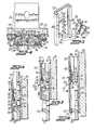
- the backrest height adjustment of the present invention is illustrated in Fig. 1 as being applied to a posture chair of the secretarial type.
- the chair includes the usual pedestal 10 having outwardly radiating legs 11 with rollers or coasters 12.
- the pedestal 10 may be vertically adjustable and a seat 13 is supported on the upper end thereof.
- the lower horizontal end portion 14 of a vertical backrest support member 15 is supported on the seat 13 in the usual manner and may be supported for inward and outward adjustment.
- a backrest 18 is supported for vertical adjustment, by means of the height adjustment device of the present invention, on the upper end portion of the support member 15 and a shroud or cover 20 is fixed on the rear of the backrest 18 and completely covers the backrest height adjustment of the present invention.
- the present backrest adjusting means includes a housing, broadly indicated at 21, which includes stamped front and rear housing plates 22, 23. Opposite side portions of the housing plates 22, 23 are bent to form mating connector flanges (Fig. 4) which are secured together by suitable nuts and screws 25.
- the housing 21 is fixed on the backrest 18 by screws 26 (Figs. 2 and 3) which extend into and their inner ends are threadably supported in Teenuts 27.
- the front plate 23 (Fig. 2) is provided with an inverted T-shaped cutout 30 and opposite sides of the cutout 30 are bent inwardly to form a pair of pivot plates 31.
- a pawl, broadly indicated at 32, is provided with a pair of side pivot plates 33 (Fig. 5) which are positioned inside of the pivot plates 31 of the housing 21 and are pivotally connected thereto, as indicated at 34 in Fig. 3, so that the pawl 32 is pivotally connected to the housing 21.
- the lower end portion of the pivot pawl 32 is provided with a pair of downwardly angled ratchet fingers 35 and an operating tongue 36 extending outwardly between the ratchet fingers 35.
- the upper end of the pivot pawl 32 is provided with a pair of upstanding stop legs 37.
- Spring means in the form of a tension spring 40, is connected at its lower end to holes provided in the tongue 36 of the pawl 32.
- the upper end of the spring 40 is suitably connected to the lower end of an inwardly bent portion of the front plate 23, forming a spring perch 42, which may be bent inwardly and outwardly to adjust the position of the upper end of the spring 40.
- the upper end portion of the support member 15 is provided with notch means extending vertically therealong and is illustrated as including a slot 43 (Fig. 5) with spaced notches 44 extending along opposite sides thereof.
- the tongue 36 of the pawl 42 is adapted to ride in the slot 43 and the ratchet fingers 35 are adapted to engage the notches 44 when the backrest 18 is moved upwardly and the pawl 32 is in the operative position.
- the lower end of the notch means is provided with an inwardly curved cam member 45 (Figs. 5-8) which forms a part of the pivot pawl operator means, to be presently described.
- the support member 15 is provided with forwardly bent flanges at each side thereof to lend rigidity thereto and rear slide guide bars 47 are supported in the rear plate 22 and slidably engage the rear portion of the support member 15.
- Slide guide bars 48 are supported in the front plate 23 and engage the front edges and sides of the support member 15.
- the guide bars 47, 48 are formed of suitable plastic material so that the housing 21 is supported for free vertical sliding movement on the support member 15.
- Operator means is associated with the upper and lower ends of the notch means and is adapted to be engaged by the pawl 32 and to switch the same between the operative and inoperative positions.
- the ratchet fingers 35 will resiliently engage the notches 44 and the pawl 32 will move in a counterclockwise direction when the desired level is reached so that the lower ends of the ratchet fingers 35 will engage the bottom of the notch 44 and the stop legs 37 will engage the inner surface of the front plate 23, as shown in Fig. 6, and maintain the backrest 18 in the adjusted position.
- the backrest 18 and the housing 21 are raised to the uppermost position where an inwardly bent stop 50 (Fig. 8) engages cam member 45.
- the tongue 36 of the pawl 32 engages the upper end of the slot 43 and the pawl 32 is moved a sufficient distance in a clockwise direction so that the longitudinal axis of the spring 40 will be positioned rearwardly of the pivot point 34 of the pawl 32.
- the spring 40 will then switch the pawl 32 to the inoperative position shown in Fig. 8 and the backrest 18 and the housing 21 can then be lowered down the support member 15.
- the tongue 36 of the pawl 32 engages the cam member 45, causing the pawl 32 to move in a counterclockwise direction so that the longitudinal axis of the spring 40 then moves forwardly of the pivot point 34, as shown in Fig. 6, to switch the pawl 32 to the operative position.
- the spring 40 resiliently urges the pawl 32 in a counterclockwise direction with the downwardly angled upper surfaces of the ratchet fingers 35 in position to engage and ride up the notches 44 when the backrest 18 is again raised.
- the lower ends of the ratchet fingers 35 will engage and be supported on the corresponding notches 44 and support the backrest 18 in the adjusted position.
- the pawl 32 is resiliently maintained in the operative position, with the ratchet fingers 35 being resiliently urged against the notches 44, when the backrest 18 is being raised.
- the pawl 32 Upon reaching the upper end of the slot 43, the pawl 32 is switched to the inoperative position with the ratchet fingers 35 out of engagement with the notches 44.
- the pawl 32 With the longitudinal axis of the spring 40 positioned rearwardly of the pivot point 34 of the pawl 32, the pawl 32 is resiliently maintained in the inoperative- position and the backrest 18 and the housing 21 are then moved to the lowermost position to reset the pawl 32 in the operative position in preparation for making a subsequent vertical adjustment of the backrest 18.
- the backrest 18 When it is desired to adjust the backrest 18 upwardly from any given adjusted position, it is merely necessary to lift the backrest 18 to the desired position. If it is desired to lower the backrest 18 below a previously adjusted position, the backrest 18 is first raised to its uppermost limit, to switch the pawl 32 to the inoperative position. The backrest 18 is then moved to its lowermost position to reset the pawl 32 to the operative position. Then, the backrest 18 is raised to the desired position and maintained in the adjusted position. These up and down movements of the backrest 18 can be easily made by a person while in the normal seated position.
Landscapes
- Chair Legs, Seat Parts, And Backrests (AREA)
- Helmets And Other Head Coverings (AREA)
- Mechanical Control Devices (AREA)
- Automotive Seat Belt Assembly (AREA)
- Chairs For Special Purposes, Such As Reclining Chairs (AREA)
Applications Claiming Priority (2)
| Application Number | Priority Date | Filing Date | Title |
|---|---|---|---|
| US06/330,280 US4451084A (en) | 1981-12-14 | 1981-12-14 | Backrest height adjustment for office chair |
| US330280 | 1981-12-14 |
Publications (2)
| Publication Number | Publication Date |
|---|---|
| EP0081898A2 true EP0081898A2 (fr) | 1983-06-22 |
| EP0081898A3 EP0081898A3 (fr) | 1984-10-17 |
Family
ID=23289062
Family Applications (1)
| Application Number | Title | Priority Date | Filing Date |
|---|---|---|---|
| EP82304871A Ceased EP0081898A3 (fr) | 1981-12-14 | 1982-09-16 | Dispositif de réglage |
Country Status (4)
| Country | Link |
|---|---|
| US (1) | US4451084A (fr) |
| EP (1) | EP0081898A3 (fr) |
| AU (1) | AU551583B2 (fr) |
| CA (1) | CA1180655A (fr) |
Cited By (8)
| Publication number | Priority date | Publication date | Assignee | Title |
|---|---|---|---|---|
| FR2586918A1 (fr) * | 1985-09-10 | 1987-03-13 | Milsco Mfg Co | Mecanisme de reglage de hauteur pour dossier de chaise |
| EP0594093A1 (fr) * | 1992-10-20 | 1994-04-27 | WILHELM LINK GmbH & Co. KG Stahlrohrmöbel | Chaise, notamment chaise de bureau |
| EP0743035A1 (fr) * | 1995-05-17 | 1996-11-20 | Martin Bock Kunststoffverarbeitung | Chaise, notamment chaise de bureau, avec un dossier réglable en hauteur |
| US5599067A (en) * | 1995-06-07 | 1997-02-04 | Herman Miller, Inc. | Adjustable arm rest assembly |
| US5667277A (en) * | 1995-06-07 | 1997-09-16 | Herman Miller Inc. | Height adjustable arm rest assembly |
| US5685609A (en) * | 1995-03-21 | 1997-11-11 | Miotto International Company | Mechanism to adjust the height of a back support of a chair |
| EP0839479A3 (fr) * | 1996-11-05 | 2000-03-22 | Nowy Styl sp. z o.o. | Dispositif de sécurité, notamment pour mécanisme de levage d'un dossier de chaise ou de fauteuil |
| US6733080B2 (en) | 1992-06-15 | 2004-05-11 | Herman Miller, Inc. | Seating structure having a backrest with a flexible membrane and a moveable armrest |
Families Citing this family (61)
| Publication number | Priority date | Publication date | Assignee | Title |
|---|---|---|---|---|
| DE3233104C1 (de) * | 1982-09-07 | 1983-12-15 | Röder GmbH Sitzmöbelwerke, 6000 Frankfurt | Stuhl mit hoehenverstellbarer Rueckenlehne |
| DE3370849D1 (en) * | 1982-09-28 | 1987-05-14 | Latchways Ltd | Releasable locking, coupling or support device |
| CA1220407A (fr) * | 1983-09-07 | 1987-04-14 | Paolo Favaretto | Chaise reglable |
| US4589696A (en) * | 1984-07-12 | 1986-05-20 | Tachikawa Spring Co., Ltd. | Adjustment/engagement device in a vehicle seat |
| DE8507806U1 (de) * | 1985-03-16 | 1985-04-25 | Ferdinand Lusch Gmbh & Co Kg, 4800 Bielefeld | Verstellbeschlag |
| US4632458A (en) * | 1985-05-20 | 1986-12-30 | Fixtures Manufacturing Corporation | Chair back height adjustment mechanism |
| US4749230A (en) * | 1987-04-23 | 1988-06-07 | Tornero Lino E | Height adjusting device for chair backrest |
| NO165054C (no) * | 1988-09-07 | 1990-12-19 | Asbjoernsen & Jan Lade A S Sve | Anordning ved omstillbar ryggstoepute paa stol. |
| US5007678A (en) * | 1989-10-11 | 1991-04-16 | Steelcase Inc. | Chair back height adjustment mechanism |
| US5037158A (en) * | 1990-01-16 | 1991-08-06 | Westinghouse Electric Corporation | Height adjustment mechanism for chair back |
| US5232265A (en) * | 1992-02-11 | 1993-08-03 | Shepherd Products U.S., Inc. | Vertical back adjust for chairs |
| DE4230230A1 (de) * | 1992-09-10 | 1994-03-17 | Dauphin Friedrich W Gmbh | Armlehne für Sitzmöbel |
| US5419617A (en) * | 1993-06-08 | 1995-05-30 | Hon Industries, Inc. | Detachable chair arm |
| US5415459A (en) * | 1993-06-08 | 1995-05-16 | Hon Industries, Inc. | Adjustable width arm rest |
| US5582460A (en) * | 1993-06-11 | 1996-12-10 | Hon Industries Inc. | Pivotable and height-adjustable chair back rest assembly and blow-molded back rest therefor |
| IT231191Y1 (it) * | 1993-12-07 | 1999-07-12 | Citton & C Sas N | Dispositivo per il fissaggio dello schienale di una poltroncina o simile alla struttura di supporto |
| US5630650A (en) * | 1994-03-30 | 1997-05-20 | Steelcase Inc. | Vertically adjustable back construction for seating |
| US6554364B1 (en) | 1995-02-17 | 2003-04-29 | Steelcase Development Corporation | Articulating armrest |
| US5586809A (en) * | 1995-08-04 | 1996-12-24 | Herman Miller, Inc. | Height adjustment mechanism for a chair backrest |
| US5597204A (en) * | 1995-08-04 | 1997-01-28 | Herman Miller, Inc. | Height adjustment device |
| US5695249A (en) * | 1996-06-24 | 1997-12-09 | Lotfi; Mehdian | Height adjustment mechanism for chair components |
| US5725278A (en) * | 1996-10-03 | 1998-03-10 | Itw Plastiglide | Chair back height adjuster |
| US5853222A (en) * | 1997-06-06 | 1998-12-29 | Haworth, Inc. | Height-adjustable chair back |
| US6250715B1 (en) | 1998-01-21 | 2001-06-26 | Herman Miller, Inc. | Chair |
| GB9802447D0 (en) | 1998-02-04 | 1998-04-01 | Unit Press Limited | Mechanism for chair |
| US6007150A (en) * | 1998-03-08 | 1999-12-28 | Milsco Manufacturing Company | Motorcycle seat with adjustable backrest |
| GB9811209D0 (en) * | 1998-05-22 | 1998-07-22 | Unit Press Limited | Height adjustment for back part of chair |
| US5918941A (en) * | 1998-08-17 | 1999-07-06 | Kigel; Rudolf | Headrest mounting assembly for a chair and the like |
| US5951107A (en) * | 1998-10-28 | 1999-09-14 | Tornero; Lino E. | Height adjusting device with audible feedback |
| GB9928509D0 (en) | 1999-12-03 | 2000-02-02 | Unit Press Limited | Improvements to chairs |
| US6598841B2 (en) * | 2000-06-07 | 2003-07-29 | Hon Technology Inc. | Height adjustable table leg |
| DE10039501A1 (de) * | 2000-08-12 | 2002-02-28 | Grammer Ag | Verstell-Vorrichtung |
| US6422652B1 (en) | 2000-11-29 | 2002-07-23 | Haworth, Inc. | Height adjusting mechanism |
| US6533355B2 (en) | 2001-03-28 | 2003-03-18 | Haworth, Inc. | Height-adjustment mechanism for a chair |
| CA2404803A1 (fr) * | 2001-09-25 | 2003-03-25 | Hon Technology Inc. | Mecanisme de reglage de chaise |
| US6616236B1 (en) * | 2002-12-14 | 2003-09-09 | Tung-Hua Su | Adjustable headrest device |
| EP1470951B1 (fr) * | 2003-04-26 | 2007-10-24 | Grammer Ag | Dispositif de réglage à cliquets |
| US7243997B1 (en) | 2004-01-20 | 2007-07-17 | Tornero Lino E | Positioning device for furniture |
| US6824218B1 (en) | 2004-01-30 | 2004-11-30 | Knoll, Inc. | Height adjustment mechanism for a chair |
| US7188901B2 (en) * | 2004-12-17 | 2007-03-13 | Leggett & Platt Ltd. | Chair adjustment mechanism |
| CN2812706Y (zh) * | 2005-03-18 | 2006-09-06 | 纪清辉 | 椅背升降机构 |
| US20070040419A1 (en) * | 2005-08-16 | 2007-02-22 | Lapointe Larry P | Foldable pawl and ratchet assembly |
| BRPI0823265A2 (pt) | 2007-01-29 | 2013-11-12 | Miller Herman Inc | Estrutura de assento e métodos para uso da mesma |
| US9668582B2 (en) * | 2015-01-15 | 2017-06-06 | Ram Machines (1990) Ltd. | Linear adjustment mechanism |
| US10363951B2 (en) * | 2015-06-11 | 2019-07-30 | Safe-Strap Company, Llc | Child restraint for child seat |
| US9585483B2 (en) * | 2015-06-29 | 2017-03-07 | Yao-Chuan Wu | Adjustable head support apparatus |
| US10092106B2 (en) | 2015-07-14 | 2018-10-09 | La-Z-Boy Incorporated | Recliner and legrest mechanism for a furniture member |
| US9986835B2 (en) | 2016-09-22 | 2018-06-05 | La-Z-Boy Incorporated | Furniture member having cam tilt mechanism |
| TWI622370B (zh) * | 2017-03-21 | 2018-05-01 | Up and down adjustment structure of the headrest of the chair | |
| US10568428B2 (en) | 2017-04-07 | 2020-02-25 | La-Z-Boy Incorporated | Furniture member having flexible seatback |
| US10537178B2 (en) | 2017-04-07 | 2020-01-21 | La-Z-Boy Incorporated | Furniture member having flexible seatback |
| US10524575B2 (en) | 2018-04-16 | 2020-01-07 | La-Z-Boy Incorporated | Furniture member with foldable pawl and ratchet assembly |
| US10426269B1 (en) * | 2018-04-30 | 2019-10-01 | Buzz Seating, Inc. | Chair with appendage accommodations |
| US10820708B2 (en) | 2018-05-18 | 2020-11-03 | La-Z-Boy Incorporated | Furniture member with wall-proximity mechanism and locking trigger |
| US10524574B2 (en) | 2018-05-18 | 2020-01-07 | La-Z-Boy Incorporated | Furniture member with powered wall-proximity mechanism |
| US11589678B2 (en) | 2019-01-17 | 2023-02-28 | Hni Technologies Inc. | Chairs including flexible frames |
| WO2020227658A1 (fr) | 2019-05-09 | 2020-11-12 | La-Z-Boy Incorporated | Chaise longue inclinable |
| US11197549B1 (en) | 2020-09-28 | 2021-12-14 | La-Z-Boy Incorporated | Wall-proximity furniture member having sync mechanism |
| US12478185B2 (en) | 2022-03-18 | 2025-11-25 | La-Z-Boy Incorporated | Reclining chaise mechanism |
| US12622521B2 (en) | 2022-12-05 | 2026-05-12 | La-Z-Boy Incorporated | Rocking and reclining wall proximity furniture member |
| US12588765B2 (en) | 2023-05-04 | 2026-03-31 | La-Z-Boy Incorporated | Rocking furniture member with power synchronous mechanism |
Family Cites Families (22)
| Publication number | Priority date | Publication date | Assignee | Title |
|---|---|---|---|---|
| US1204858A (en) * | 1913-10-27 | 1916-11-14 | Guy Moore Gest | Cable-bracket. |
| US1679168A (en) * | 1926-02-15 | 1928-07-31 | James F O'brien | Adjustable stilt |
| US2096452A (en) * | 1933-04-22 | 1937-10-19 | George L Eber | Telescoping case coupling members |
| US2264382A (en) * | 1937-06-30 | 1941-12-02 | Motor State Products Company | Self-locking check arm |
| US2221123A (en) * | 1937-08-26 | 1940-11-12 | William R Wiley | Trunk lid support |
| US2229513A (en) * | 1938-06-24 | 1941-01-21 | Atwood Vacuum Machine Co | Lid support |
| US2392477A (en) * | 1942-08-21 | 1946-01-08 | Holm S Mfg Company | Adjustable seat base |
| US2405013A (en) * | 1942-11-19 | 1946-07-30 | Charles T Campbell | Chair |
| US2378852A (en) * | 1943-05-27 | 1945-06-19 | Robert H Jamison | Adjustable table and like furniture |
| GB665026A (en) * | 1948-06-18 | 1952-01-16 | Svenska Flaektfabriken Ab | Apparatus for securing a pulling member in different longitudinal positions |
| US2643922A (en) * | 1951-04-13 | 1953-06-30 | Edward G Rudman | Vertically adjustable table top |
| US2975994A (en) * | 1959-03-05 | 1961-03-21 | James W Goss | Picture hanging bracket |
| DE1429584A1 (de) * | 1964-02-15 | 1973-08-09 | Ilse Werke Kg | Nichtverdrehbarer teleskopfuss fuer moebel |
| US3526430A (en) * | 1968-11-18 | 1970-09-01 | Art Metal Knoll Corp | Back height adjustment mechanism |
| US3563603A (en) * | 1969-09-04 | 1971-02-16 | Ford Motor Co | Headrest assembly |
| GB1371641A (en) * | 1971-11-23 | 1974-10-23 | Parnall & Sons Ltd | Chairs |
| US3854428A (en) * | 1973-05-14 | 1974-12-17 | Hill Rom Co Inc | Overbed table |
| US3860286A (en) * | 1973-07-27 | 1975-01-14 | Hek Manufacturing Company Inc | Split back dental chair apparatus |
| US3952987A (en) * | 1974-10-24 | 1976-04-27 | Bevco Precision Manufacturing Company | Chair adjustment construction |
| DE2809991C2 (de) * | 1978-03-08 | 1980-01-31 | Fa. Wilhelm Baumeister, 4803 Steinhagen | Teleskopstütze für hochstellbare Enden von Liegen oder Bettrosten |
| US4221430A (en) * | 1978-05-18 | 1980-09-09 | Jasper Corporation | Push button adjuster for chair backrest |
| US4384742A (en) * | 1981-03-11 | 1983-05-24 | Haworth, Inc. | Height adjusting mechanism for chair back |
-
1981
- 1981-12-14 US US06/330,280 patent/US4451084A/en not_active Expired - Fee Related
-
1982
- 1982-09-09 AU AU88158/82A patent/AU551583B2/en not_active Expired - Fee Related
- 1982-09-16 EP EP82304871A patent/EP0081898A3/fr not_active Ceased
- 1982-10-18 CA CA000413613A patent/CA1180655A/fr not_active Expired
Cited By (10)
| Publication number | Priority date | Publication date | Assignee | Title |
|---|---|---|---|---|
| FR2586918A1 (fr) * | 1985-09-10 | 1987-03-13 | Milsco Mfg Co | Mecanisme de reglage de hauteur pour dossier de chaise |
| GB2180147A (en) * | 1985-09-10 | 1987-03-25 | Milsco Mfg Co | Height adjustment mechanism for chair backrest |
| GB2180147B (en) * | 1985-09-10 | 1989-09-06 | Milsco Mfg Co | Height adjustment mechanism for chair backrest |
| US6733080B2 (en) | 1992-06-15 | 2004-05-11 | Herman Miller, Inc. | Seating structure having a backrest with a flexible membrane and a moveable armrest |
| EP0594093A1 (fr) * | 1992-10-20 | 1994-04-27 | WILHELM LINK GmbH & Co. KG Stahlrohrmöbel | Chaise, notamment chaise de bureau |
| US5685609A (en) * | 1995-03-21 | 1997-11-11 | Miotto International Company | Mechanism to adjust the height of a back support of a chair |
| EP0743035A1 (fr) * | 1995-05-17 | 1996-11-20 | Martin Bock Kunststoffverarbeitung | Chaise, notamment chaise de bureau, avec un dossier réglable en hauteur |
| US5599067A (en) * | 1995-06-07 | 1997-02-04 | Herman Miller, Inc. | Adjustable arm rest assembly |
| US5667277A (en) * | 1995-06-07 | 1997-09-16 | Herman Miller Inc. | Height adjustable arm rest assembly |
| EP0839479A3 (fr) * | 1996-11-05 | 2000-03-22 | Nowy Styl sp. z o.o. | Dispositif de sécurité, notamment pour mécanisme de levage d'un dossier de chaise ou de fauteuil |
Also Published As
| Publication number | Publication date |
|---|---|
| AU8815882A (en) | 1983-06-23 |
| US4451084A (en) | 1984-05-29 |
| CA1180655A (fr) | 1985-01-08 |
| EP0081898A3 (fr) | 1984-10-17 |
| AU551583B2 (en) | 1986-05-08 |
Similar Documents
| Publication | Publication Date | Title |
|---|---|---|
| US4451084A (en) | Backrest height adjustment for office chair | |
| US5829839A (en) | Height-adjustable chair arm assembly having gear-type adjusting mechanism | |
| US5035466A (en) | Ergonomic chair | |
| EP1364603B1 (fr) | Chaise haute pour enfants à réglage aisé | |
| US7841665B2 (en) | Height adjustable armrest | |
| US5007678A (en) | Chair back height adjustment mechanism | |
| US6296312B1 (en) | Armrest assembly | |
| US6053579A (en) | Height-Adjustable chair arm assembly having cam-type adjusting mechanism | |
| US5558400A (en) | Adjustable height high chair | |
| US6139103A (en) | Synchronized chair seat and backrest tilt control mechanism | |
| US6840582B2 (en) | Height adjustable arm assembly | |
| US4466665A (en) | Chair having adjsutable, cantilevered lumbar-supporting arm | |
| US20020140266A1 (en) | Height-adjustment mechanism for a chair | |
| JP6527623B1 (ja) | 椅子 | |
| EP0482439B1 (fr) | Point d'attache pour une chaise | |
| US6540296B1 (en) | Chair back height-adjustment mechanism | |
| KR20140065308A (ko) | 의자의 머리받침 부재 조절 장치 | |
| US20060131944A1 (en) | Chair adjustment mechanism | |
| JP6009627B2 (ja) | 椅子及びその座アウターシェル | |
| US11490732B2 (en) | Stairlift chair | |
| JP2015171652A5 (fr) | ||
| US7431397B2 (en) | Chair | |
| KR101265898B1 (ko) | 가변식 요추받침 장치를 갖는 의자 등받이 | |
| KR200409172Y1 (ko) | 의자등받이의 각도 조절장치 | |
| EP1716786A1 (fr) | Chaise ou fauteuil avec appui tête règlable |
Legal Events
| Date | Code | Title | Description |
|---|---|---|---|
| PUAI | Public reference made under article 153(3) epc to a published international application that has entered the european phase |
Free format text: ORIGINAL CODE: 0009012 |
|
| AK | Designated contracting states |
Designated state(s): AT BE CH DE FR GB IT LI LU NL SE |
|
| PUAL | Search report despatched |
Free format text: ORIGINAL CODE: 0009013 |
|
| AK | Designated contracting states |
Designated state(s): AT BE CH DE FR GB IT LI LU NL SE |
|
| 17P | Request for examination filed |
Effective date: 19841228 |
|
| STAA | Information on the status of an ep patent application or granted ep patent |
Free format text: STATUS: THE APPLICATION HAS BEEN REFUSED |
|
| 18R | Application refused |
Effective date: 19870216 |
|
| RIN1 | Information on inventor provided before grant (corrected) |
Inventor name: SEELEY, WAYNE C. |