EP0081904A1 - Commande de tension variable pour alternateur synchrone auto-excité et auto-régulé - Google Patents
Commande de tension variable pour alternateur synchrone auto-excité et auto-régulé Download PDFInfo
- Publication number
- EP0081904A1 EP0081904A1 EP82305819A EP82305819A EP0081904A1 EP 0081904 A1 EP0081904 A1 EP 0081904A1 EP 82305819 A EP82305819 A EP 82305819A EP 82305819 A EP82305819 A EP 82305819A EP 0081904 A1 EP0081904 A1 EP 0081904A1
- Authority
- EP
- European Patent Office
- Prior art keywords
- alternator
- exciter
- voltage
- control
- field
- Prior art date
- Legal status (The legal status is an assumption and is not a legal conclusion. Google has not performed a legal analysis and makes no representation as to the accuracy of the status listed.)
- Withdrawn
Links
- 230000001105 regulatory effect Effects 0.000 title abstract description 9
- 230000001360 synchronised effect Effects 0.000 title abstract description 9
- 238000004804 winding Methods 0.000 claims abstract description 36
- 230000000694 effects Effects 0.000 claims description 7
- 230000004044 response Effects 0.000 claims description 6
- 230000005284 excitation Effects 0.000 claims description 3
- 239000004020 conductor Substances 0.000 claims 2
- 230000008878 coupling Effects 0.000 claims 1
- 238000010168 coupling process Methods 0.000 claims 1
- 238000005859 coupling reaction Methods 0.000 claims 1
- 239000000463 material Substances 0.000 claims 1
- 239000003990 capacitor Substances 0.000 description 22
- 230000001276 controlling effect Effects 0.000 description 6
- 230000004907 flux Effects 0.000 description 6
- 239000004065 semiconductor Substances 0.000 description 5
- 230000008859 change Effects 0.000 description 4
- 230000008901 benefit Effects 0.000 description 2
- 238000010586 diagram Methods 0.000 description 2
- 238000010304 firing Methods 0.000 description 2
- 230000001939 inductive effect Effects 0.000 description 2
- 229920006395 saturated elastomer Polymers 0.000 description 2
- XUIMIQQOPSSXEZ-UHFFFAOYSA-N Silicon Chemical compound [Si] XUIMIQQOPSSXEZ-UHFFFAOYSA-N 0.000 description 1
- 230000002159 abnormal effect Effects 0.000 description 1
- 239000000956 alloy Substances 0.000 description 1
- 229910045601 alloy Inorganic materials 0.000 description 1
- 230000009849 deactivation Effects 0.000 description 1
- 230000008030 elimination Effects 0.000 description 1
- 238000003379 elimination reaction Methods 0.000 description 1
- 239000000696 magnetic material Substances 0.000 description 1
- 230000007246 mechanism Effects 0.000 description 1
- 238000000034 method Methods 0.000 description 1
- 230000001681 protective effect Effects 0.000 description 1
- 229910052710 silicon Inorganic materials 0.000 description 1
- 239000010703 silicon Substances 0.000 description 1
- 230000001960 triggered effect Effects 0.000 description 1
Images
Classifications
-
- H—ELECTRICITY
- H02—GENERATION; CONVERSION OR DISTRIBUTION OF ELECTRIC POWER
- H02P—CONTROL OR REGULATION OF ELECTRIC MOTORS, ELECTRIC GENERATORS OR DYNAMO-ELECTRIC CONVERTERS; CONTROLLING TRANSFORMERS, REACTORS OR CHOKE COILS
- H02P9/00—Arrangements for controlling electric generators for the purpose of obtaining a desired output
- H02P9/14—Arrangements for controlling electric generators for the purpose of obtaining a desired output by variation of field
- H02P9/36—Arrangements for controlling electric generators for the purpose of obtaining a desired output by variation of field using armature-reaction-excited machines
-
- H—ELECTRICITY
- H02—GENERATION; CONVERSION OR DISTRIBUTION OF ELECTRIC POWER
- H02K—DYNAMO-ELECTRIC MACHINES
- H02K19/00—Synchronous motors or generators
- H02K19/16—Synchronous generators
- H02K19/26—Synchronous generators characterised by the arrangement of exciting windings
- H02K19/30—Synchronous generators characterised by the arrangement of exciting windings for compounding
-
- H—ELECTRICITY
- H02—GENERATION; CONVERSION OR DISTRIBUTION OF ELECTRIC POWER
- H02P—CONTROL OR REGULATION OF ELECTRIC MOTORS, ELECTRIC GENERATORS OR DYNAMO-ELECTRIC CONVERTERS; CONTROLLING TRANSFORMERS, REACTORS OR CHOKE COILS
- H02P9/00—Arrangements for controlling electric generators for the purpose of obtaining a desired output
- H02P9/14—Arrangements for controlling electric generators for the purpose of obtaining a desired output by variation of field
- H02P9/38—Self-excitation by current derived from rectification of both output voltage and output current of generator
Definitions
- the present invention relates to synchronous alternators preferably of the self-excited self-regulated, brushless type, and, more particularly, to an adjustable voltage control for such alternators or the like.
- a dynamo electric machine of the self-excited self-regulated synchronous alternator type is disclosed in Sparrow U.S. Patent No. 3,210,644.
- Such machine includes a main generator stator or armature and a rotating field winding.
- An exciter stator primary winding energized by an output from the main generator stator correspondingly produces a signal in a rotating exciter secondary.
- the exciter secondary in turn delivers a signal to the rotating field to produce a signal in the main generator stator which delivers an electrical output to a load.
- a rectifier for completing a circuit between the exciter secondary and the field rotates with the rotor.
- a primary object of the present invention is to obtain and to control a field-adjustable nominal terminal voltage on an alternator and especially on a self-excited, self-regulated, brushless, synchronous alternator.
- Another object is to deactivate a voltage adjust system under prescribed conditions, and especially to deactivate a voltage adjusting system of an alternator to achieve maximum exciter output voltage when there is a high alternator field demand.
- a corresponding object is to effect such deactivation automatically and especially in response to the actual field current demand.
- An additional object is to enable adjustment of output voltage of an alternator-exciter system without changing the winding configuration or arrangement; and especially to effect such adjustment under no-load and under relatively light-load conditions.
- a further object is to enable a device of the alternator-exciter type, in which each of the alternator and exciter has a specific winding arrangement and specific number of turns per coil, to be used in applications requiring different nominal voltages.
- Still another object is to provide an improved means of energizing and of controlling the alternator field winding of an alternator-exciter type device from the exciter secondary winding(s).
- Still an additional object is to effect the aforesaid adjustments using a phase angle or phase delay control, and, moreover, to maintain substantially constant such phase angle or phase delay as the magnitude of the exciter output voltage varies.
- Still a further object is to achieve the foregoing in rotating rectifier synchronous alternators.
- an electric generating device includes an alternator-exciter for producing an electrical output and an adjusting means for adjusting the output voltage of the alternator-exciter substantially independently of the winding arrangement thereof; or wherein the adjusting means provides for adjusting the field excitation of the alternator-exciter to control the nominal terminal voltage of the electrical output; or wherein the adjusting means is of the type that adjusts the output voltage of the alternator-exciter substantially independently of the winding arrangement and additionally a control is provided to control the no-load voltage of the electrical output.
- an electric generating device includes an alternator-exciter for producing an electrical output, a control provides for control of at least one parameter of the electrical output, and a deactivating device deactivates the control during operation of the device in a prescribed manner.
- Several other aspects of the invention relate to improvements for alternator type electrical generating devices, including an adjusting device for adjusting the output voltage of the generating device substantially independently of the winding arrangement thereof; or a means for adjusting the field excitation of the device to control the nominal terminal voltage of the electrical output therefrom; or a means for controling the no-load voltage of the electrical output of the device; or a means for controlling at least one parameter of the electrical output of the device and a deactivating means for deactivating the control during a prescribed manner of operation of the device.
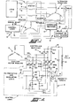
- a self-excited, self-regulated, brushless, synchronous alternator is generally shown at I including adjustable control circuitry 2 in accordance with the present invention.
- the alternator 1 includes a stator 3, which itself includes an exciter stator 4 and a main generator stator or alternator armature 5.
- the stator 3 is shown above the phantom line P in Fig. 1.
- Output leads 6 provide the electrical output from the alternator 1 to a load 7, such as an electric motor or other device that operates in response to input of electrical energy.
- the alternator 1 also includes a rotor 8, (shown on the opposite side of the phantom line P from the stator) which itself includes an exciter rotor 9 and the alternator field 10, which in the preferred embodiment is a winding or coil.
- the rotor 8 and stator 3 undergo relative rotation, and in the preferred embodiment the stator remains relatively fixed while the rotor rotates with respect thereto in response to a mechanical input, for example, from an engine or the like.
- adjustable control circuitry 2 Included in the adjustable control circuitry 2 are a controlled rectifier 15, the purpose of which is to effect control of the current to the field 10 in order to control the magnitude of the electrical output voltage on leads 6 as the current drawn by the load 7 varies, and especially during no-load or light-load conditions; a current or flux sensor 16, which monitors the current delivered to and/or the flux of the field 10, which will be representative of the effective draw of the load 7; and a controlled logic circuit 17, which effects the appropriate control of the controlled rectifier 15.
- the adjustable control circuitry 2 provides a means for adjusting the no-load and light-load output voltage or terminal voltage, e.g. on leads 6, of the alternator 1 with a specific winding configuration, i.e. without having to alter the winding configuration of the alternator 1.
- the adjustable control circuitry 2 also includes provision, such as the sensor 16, for deactivating the voltage adjusting mechanism thereof during periods of high alternator field current demand so that full exciter output voltage can be applied to the alternator field to provide a maximum voltage output capability for the alternator armature 5.
- the adjustable control circuitry 2 may be used, for example, with alternators of the type manufactured and sold by the Lima Electric Co., Inc. of Lima, Ohio under the trademark MAC.
- the alternator 1 of Fig. 1 may be one of such MAC alternators in which the alternator armature or stator 5 is a three phase wye-connected stator the alternator field 10 is a wound coil, the exciter stator 4 is a three phase set of series and shunt stator windings energized from the alternator armature 5, and the exciter rotor 9 is a three phase exciter rotor or secondary winding.
- the adjustable control circuitry 2 may be used equivalently with single phase machines or 2-phase machines and with machines that are greater than three phase.
- the nominal line voltage parameter can be adjusted from about 416 volts to about 520 volts.
- the adjustable control circuitry 2 is shown in detail. Such circuitry 2 is intended to provide the means for energizing and for controlling the alternator field winding 10.
- a conventional rectifier typically used in a rotating rectifier alternator is replaced with the controlled rectifier 15.
- the controlled rectifier 15 preferrably is a so-called half-SCR bridge including diodes 30, 31, 32 and SCR's 33, 34, 35. If desired, though, a full-SCR bridge, transistor rectifiers, controlled rectifiers using other types of devices, and the like maybe used in place of the illustrated controlled rectifier 15.
- Leads 36, 37, 38 from the respective windings of the exciter rotor 9 couple the signal induced in such exciter rotor by the exciter stator 4 to the controlled rectifier 15, and it is the purpose of the latter to control the level of energization of the alternator field 10 using a phase control technique, for example, employing signals to the gate electrodes 33g-35g of the SCR's.
- the controlled rectifier 15 is coupled between respective DC positive and negative busses 39, 40, which are, in turn, connected by leads 18, 19 across the alternator field 10.
- a free-wheeling diode 41 also may be coupled across the alternator field 10 for the usual purposes.
- the control logic circuitry 17 controls the rectifier 15, and both the former and the latter are preferrably of the illustrated type for simplicity, reliability, and reasonable price.
- the control logic circuitry 17 provides the desired phase control of the rectifier 15 being capable of delaying the turn-on or triggering of the SCR's 33-35 to vary the DC voltage output across the positive and negative busses 39, 40 from about 25% to about 95% of the voltage that would exist with a full diode bridge. Since 100% of the diode bridge voltage cannot be achieved with the illustrated controlled rectifier bridge 15, to achieve maximum rated output of the alternator 1, then, the number of turns in the respective windings of the excitor rotor or secondary 9 should be increased over the number such windings would include when the alternator is used with only a diode bridge.
- such increase should be at least the ratio percentage 1 (representing the number of turns in the ordinary alternator exciter rotor) divided by the maximum capability of the controlled rectifier 15 as a percentage of the maximum voltage output capability of a standard diode bridge.
- the number of turns in the exciter rotor windings should be increased to at least 100% divided by 95% or a total of 5% increase over the number of windings in the exciter rotor when there would be only a standard diode bridge in the alternator 1.
- a timing circuit 50 is used to trigger or to turn-on the SCR's 33-35 by controlling the delivery of gating signals to the gate terminals 33g-35g.
- the timing circuit 50 includes a unijunction transistor 51, but other types of triggering devices, such as, for example, transistors, low signal SCR's, diacs, silicon unilateral switches, programable unijunction transistors, etc. also may be used in the timing circuit 50.
- a particular advantage to the timing circuit 50 is that such circuit effects triggering of the SCR's 33-35 as a function of a voltage ratio and not in response to a fixed voltage so that the timing circuit 50 responds in an identical fashion to the varying voltage of the exciter rotor, 9.
- the exciter output voltages on leads 36-38 appear across the signal diodes 52, 53, 54.
- the cathodes of those diodes are connected together and via resistors 55, 56 and adjustable resistor or potentiometer 57 to a capacitor 58.
- the same voltages that appear across the main SCR's 33-35 of the controlled rectifier 15 appear across the signal diodes 52-54.
- the voltage across signal diode 52 is the same as that across the SCR 35.
- the unijunction transistor 51 ordinarily appears as an open circuit, and, therefore, the diode voltage just mentioned above appears across the unijunction transistor.
- the voltage across the capacitor 58 exceeds a prescibed fraction d of the voltage across the unijunction transister, the latter is triggered to conduction almost instantly and appears as a short circuit.
- the means for controlling the phase delay or time interval in each 120 degree period delaying the turn-on of the main SCR's 33-35 is the rate of charging of the capacitor 58. Manual control of such charging rate may be effected by adjustment of the variable resistor 57.
- the adjustable control circuitry 2 initially is designed and constructed, the parameters of the unijunction transistor 51, namely the fraction or turn-on ratio d and the voltage rating thereof, and the values of the resistors 55-57 and of the capacitor 58 would influence the triggering point of the main SCR's 33-35.
- the voltage adjust control is provided substantially exclusively by the variable resistor 57.
- the exciter output voltage varies as a function of load current. Therefore, the voltage across the capacitor 58 and the voltage across the source terminals of the unijunction transistor will vary with exciter output voltage, namely that appearing on leads 36-38.
- the trigger point of the unijunction transistor 51 i.e. that point in the operation thereof at which the open circuit between the source electrodes becomes a closed circuit, is determined by a percentage (the turn-on ratio d) of the open circuit voltage across those source electrodes; the capacitor 58 must charge to that percentage voltage to trigger the unijunction transistor 51 to conduction.
- the unijunction transistor trigger point is determined by a percentage of the noted open circuit voltage rather than by a fixed value of voltage, and since the capacitor 58 and open circuit voltage of the unijunction transistor 51 vary with exciter output voltage, for a set value of resistors 55-57 the time relationships, i.e. the phase delay for triggering the respective main SCR's 33-35, will remain at least substantially the same as the exciter output voltage varies and, therefore, will be independent of real time. However, by adjusting the resistor 57 to change its resistance, the time constant or charging rate of the capacitor 58 will be changed; and, therefore, the time relationships or phase delay will be changed accordingly.
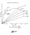
- the triggering points for the unijunction transistor 51 for several values of the charging time constant T e.g. which may be changed by adjusting the resistor of 57, are shown.
- the curves A through F represent the voltage V across the capacitor 58 as such voltage varies as a function of time with respective time constants pl.
- the time constant T, for curve A is 0.5, i.e. the product of the sum of the resistances 55, 56, 57 which may be a total of 1 Kohm and the capacitance of capacitor 58, which may be 0.5 microfarads.
- Curve G represents a tracking of the open circuit voltage V across the source electrodes of the injunction transistor 51 and, accordingly, follows the full wave rectified voltage on the bus 60 from the leads 36-38 that carry exciter output voltages from the exciter rotor winding 9. Since the alternator 1 and adjustable control circuitry 2 described in detail herein is of the three phase type, the curve G will repeat in each 120 electric degrees of the exciter output voltages. Therefore, the following equation for the voltage V p may be written as is shown in Fig. 3; the value Vex may be, for example, 20.7 volts, which is the magnitude of the AC voltage produced by an individual winding of the exciter rotor 9 at a frequency of 60 Hz.
- the trigger points or effective conduction angles i.e. where conduction in the controlled bridge 15 begins in a 120 degree portion thereof, are indicated by cross marks at the intersections of respective curves A through F with curve G.
- the magnitude of the voltage V across capacitor 58 equals the correct percentage of the open circuit voltage V p across the unijunction transistor 51, whereupon the latter fires to conduction causing a trigger pulse to be delivered to the bus 62 to which all the gate electrodes 33g-35g are connected.
- the time at which such firing/triggering occurs also is indicated in Fig. 3.
- a separate control means may be provided to alter the charging time constant T for the capacitor 58 during specified conditions of operation of the adjustable control circuitry 2, for example when large field current demand is required.
- the equivalent resistance between resistor 56 and capacitor 58 of the circuit shown in Fig. 2 can be changed by adding a controlled resistance in parallel with the actual resistor 57.
- Such controlled resistance may be added, for example by using a transistor, SCR or other semi-conductor device to short out resistor 57 as a function of the alternator field current magnitude.
- the shorting semi-conductor could be turned on by means of a Hall device or Wiegand wire from a magnectic flux signal.
- Such shorting semi-conductor could be turned on by means of a current sensor from a field current signal.
- a saturable reactor approach is employed for automatically controlling the effective resistance between resistor 56 and capacitor 58.
- the saturable reactor approach is relatively uncomplicated and inexpensive while being satisfactorily effective.
- the current or flux sensor 16 includes square-loop toroid 70 having a winding 71 with a relatively large number of turns connected electrically in parallel with the resistor 57.
- the winding 71 which is coupled by leads 72, 73 across resistor 57, presents a high inductive reactance to the signal diode (52-54) pulse voltages when the toroid 70 is unsaturated.
- the lead 19 passes through the center 74 or the toroid 70 so that at a certain value of alternator field current the toroid 70 becomes saturated; the inductance of the winding 71 then becomes negligible (with square-loop magnetic material) and effective low resistance is placed in parallel with resistor 57.
- a winding 71 of 650 turns provides an unsaturated inductive reactance of 10,000 Ohms, assuming an exciter output frequency of 120 Hz.
- the coil or winding 71 will have a resistance of about 3 ohms, which will be the effective impedance in parallel with resistor 57, when the toroid 70 is saturated.
- the effective resistance between the resistor 56 and capacitor 58 will be reduced, usually substantially by a step function, and the charging rate of the capacitor 58 will be correspondingly increased in order to minimize any phase delay of the controlled rectifier 15. Therefore, maximum voltage will be applied from the exciter rotor 9 via the controlled rectifier 15 to the field 10 in an effort to try to supply the electrical output demanded by the load 7.
- the invention may be used in connection with provision of electrical outputs from machines driven by mechanical inputs.
Landscapes
- Engineering & Computer Science (AREA)
- Power Engineering (AREA)
- Control Of Eletrric Generators (AREA)
Applications Claiming Priority (2)
| Application Number | Priority Date | Filing Date | Title |
|---|---|---|---|
| US06/320,723 US4496897A (en) | 1981-11-12 | 1981-11-12 | Variable voltage control for self-excited self-regulated synchronous alternator |
| US320723 | 1994-10-11 |
Publications (1)
| Publication Number | Publication Date |
|---|---|
| EP0081904A1 true EP0081904A1 (fr) | 1983-06-22 |
Family
ID=23247626
Family Applications (1)
| Application Number | Title | Priority Date | Filing Date |
|---|---|---|---|
| EP82305819A Withdrawn EP0081904A1 (fr) | 1981-11-12 | 1982-11-02 | Commande de tension variable pour alternateur synchrone auto-excité et auto-régulé |
Country Status (2)
| Country | Link |
|---|---|
| US (1) | US4496897A (fr) |
| EP (1) | EP0081904A1 (fr) |
Cited By (5)
| Publication number | Priority date | Publication date | Assignee | Title |
|---|---|---|---|---|
| EP0254129A1 (fr) * | 1986-07-22 | 1988-01-27 | Siemens Aktiengesellschaft | Générateur synchrone sans balai |
| EP0258760A3 (en) * | 1986-08-29 | 1989-07-19 | General Electric Company | Brushless generator exciter using hybrid rectifier |
| RU2145461C1 (ru) * | 1997-11-26 | 2000-02-10 | Кубанский государственный аграрный университет | Автономный бесконтактный синхронный генератор |
| RU2208287C2 (ru) * | 2001-08-23 | 2003-07-10 | Уральский государственный университет путей сообщения | Возбудитель синхронного генератора |
| CN102315811A (zh) * | 2010-06-29 | 2012-01-11 | 通用电气公司 | 发电机的非正弦电流波形激励的系统和方法 |
Families Citing this family (17)
| Publication number | Priority date | Publication date | Assignee | Title |
|---|---|---|---|---|
| GB8514859D0 (en) * | 1985-06-12 | 1985-07-17 | Markon Eng Co Ltd | Automatic voltage regulator |
| US5583420A (en) * | 1993-10-01 | 1996-12-10 | Lucas Aerospace Power Equipment Corporation | Microprocessor controller for starter/generator |
| US6188203B1 (en) * | 1996-11-01 | 2001-02-13 | Lucas Aerospace Power Equipment Corporation | Ground fault detection circuit |
| US5714821A (en) * | 1994-02-16 | 1998-02-03 | Marathon Electric Mfg. Corp. | Alternating current generator with direct connected exciter winding |
| DE69530828T2 (de) * | 1994-12-16 | 2004-01-22 | Delphi Technologies, Inc., Troy | Drehmoment- und Ausgang-Steuerung einer Brennkraftslichtmaschine |
| US5663632A (en) * | 1995-07-17 | 1997-09-02 | Lucas Aerospace Power Equipment Corp. | Field current control for generator during build-up |
| US6153942A (en) * | 1995-07-17 | 2000-11-28 | Lucas Aerospace Power Equipment Corp. | Starter/generator speed sensing using field weakening |
| US5648705A (en) * | 1995-09-05 | 1997-07-15 | Ford Motor Company | Motor vehicle alternator and methods of operation |
| US6310469B1 (en) * | 2000-06-19 | 2001-10-30 | Texas Instruments Incorporated | System and method to detect synchronous switching regulator light load |
| US7102331B2 (en) * | 2003-01-17 | 2006-09-05 | Black & Decker Inc. | Generator with dual cycloconverter for 120/240 VAC operation |
| GB0519679D0 (en) * | 2005-09-27 | 2005-11-02 | Newage Int Ltd | Power control circuit |
| US7541784B2 (en) * | 2006-05-26 | 2009-06-02 | Endurance Wind Power | Dual voltage switching in power generation |
| US20120126758A1 (en) * | 2010-11-19 | 2012-05-24 | Hamilton Sundstrand Corporation | High voltage dc power generation |
| RU2465706C1 (ru) * | 2011-03-25 | 2012-10-27 | Государственное образовательное учреждение высшего профессионального образования "Кубанский государственный технологический университет" (ГОУ ВПО "КубГТУ") | Стабилизированный аксиальный бесконтактный генератор постоянного тока |
| EP2786480B1 (fr) * | 2011-11-28 | 2020-07-22 | ABB Schweiz AG | Machine électrique rotative |
| US9562715B2 (en) * | 2012-03-21 | 2017-02-07 | Thermo King Corporation | Power regulation system for a mobile environment-controlled unit and method of controlling the same |
| CN105301353A (zh) * | 2014-06-30 | 2016-02-03 | 中国南方航空工业(集团)有限公司 | 交流电源系统控制盒的检测系统和方法 |
Citations (4)
| Publication number | Priority date | Publication date | Assignee | Title |
|---|---|---|---|---|
| US3210644A (en) * | 1960-02-08 | 1965-10-05 | Lima Electric Motor Co Inc | Dynamo electric machine |
| GB1339739A (en) * | 1969-12-18 | 1973-12-05 | Mitsubishi Electric Corp | Brushless rotary electric machine |
| GB1414966A (en) * | 1971-10-25 | 1975-11-19 | Reyrolle Parsons Ltd | Dynamo-electric machines |
| FR2437104A1 (fr) * | 1978-09-20 | 1980-04-18 | Voskoboinikov Roman | Regulateur de tension pour alternateur synchrone |
Family Cites Families (4)
| Publication number | Priority date | Publication date | Assignee | Title |
|---|---|---|---|---|
| DE1538322C3 (de) * | 1966-02-15 | 1974-01-17 | Robert Bosch Gmbh, 7000 Stuttgart | Transistor-Spannungsregler |
| US3596169A (en) * | 1969-10-16 | 1971-07-27 | Victoreen Leece Neville Inc | Regulating circuit employing a saturable reactor |
| JPS5233522Y2 (fr) * | 1971-08-14 | 1977-07-30 | ||
| CA1097738A (fr) * | 1976-08-20 | 1981-03-17 | Westinghouse Electric Corporation | Methode de desexcitation rapide d'une excitatrice sans balai |
-
1981
- 1981-11-12 US US06/320,723 patent/US4496897A/en not_active Expired - Fee Related
-
1982
- 1982-11-02 EP EP82305819A patent/EP0081904A1/fr not_active Withdrawn
Patent Citations (4)
| Publication number | Priority date | Publication date | Assignee | Title |
|---|---|---|---|---|
| US3210644A (en) * | 1960-02-08 | 1965-10-05 | Lima Electric Motor Co Inc | Dynamo electric machine |
| GB1339739A (en) * | 1969-12-18 | 1973-12-05 | Mitsubishi Electric Corp | Brushless rotary electric machine |
| GB1414966A (en) * | 1971-10-25 | 1975-11-19 | Reyrolle Parsons Ltd | Dynamo-electric machines |
| FR2437104A1 (fr) * | 1978-09-20 | 1980-04-18 | Voskoboinikov Roman | Regulateur de tension pour alternateur synchrone |
Cited By (11)
| Publication number | Priority date | Publication date | Assignee | Title |
|---|---|---|---|---|
| EP0254129A1 (fr) * | 1986-07-22 | 1988-01-27 | Siemens Aktiengesellschaft | Générateur synchrone sans balai |
| EP0258760A3 (en) * | 1986-08-29 | 1989-07-19 | General Electric Company | Brushless generator exciter using hybrid rectifier |
| RU2145461C1 (ru) * | 1997-11-26 | 2000-02-10 | Кубанский государственный аграрный университет | Автономный бесконтактный синхронный генератор |
| RU2208287C2 (ru) * | 2001-08-23 | 2003-07-10 | Уральский государственный университет путей сообщения | Возбудитель синхронного генератора |
| CN102315811A (zh) * | 2010-06-29 | 2012-01-11 | 通用电气公司 | 发电机的非正弦电流波形激励的系统和方法 |
| EP2403129A3 (fr) * | 2010-06-29 | 2013-04-24 | General Electric Company | Système et procédé pour l'excitation de forme d'onde à courant non sinusoïdal de générateurs électriques |
| US8901896B2 (en) | 2010-06-29 | 2014-12-02 | General Electric Company | System and method for non-sinusoidal current waveform excitation of electrical generators |
| US9118271B2 (en) | 2010-06-29 | 2015-08-25 | General Electric Company | System and method for non-sinusoidal current waveform excitation of electrical generators |
| CN102315811B (zh) * | 2010-06-29 | 2015-09-16 | 通用电气公司 | 发电机的非正弦电流波形激励的系统和方法 |
| CN105006935A (zh) * | 2010-06-29 | 2015-10-28 | 通用电气公司 | 发电机的非正弦电流波形激励的系统和方法 |
| CN105006935B (zh) * | 2010-06-29 | 2017-11-17 | 通用电气公司 | 发电机的非正弦电流波形激励的系统和方法 |
Also Published As
| Publication number | Publication date |
|---|---|
| US4496897A (en) | 1985-01-29 |
Similar Documents
| Publication | Publication Date | Title |
|---|---|---|
| US4496897A (en) | Variable voltage control for self-excited self-regulated synchronous alternator | |
| US4264856A (en) | System for maintaining excitation of an alternating current generator during excessive output current conditions | |
| EP0113503A1 (fr) | Commande triphasée de facteur de puissance avec sonde de mesure de force électromotrice induite | |
| EP0114274A1 (fr) | Système de commande et de stabilisation pour moteur synchrone sans amortisseur | |
| US3441823A (en) | Tachometerless induction motor speed control | |
| US3577176A (en) | Constant current step motor system | |
| US4378517A (en) | Method and apparatus for controlling the energization of an electric motor | |
| US4105963A (en) | Brushless welding generator | |
| US5220258A (en) | Drive circuit for a brushless direct-current motor | |
| US3355646A (en) | Optimum driving method for step motors | |
| US2540202A (en) | Dynamoelectric machine | |
| US4599552A (en) | Generator voltage regulator | |
| US2650341A (en) | Voltage regulator | |
| US3289071A (en) | Voltage regulator | |
| US3621369A (en) | Automatic voltage regulating apparatus for ac generator with antihunt means | |
| EP0238502A1 (fr) | Procede et dispositif de freinage d'un moteur asynchrone | |
| EP0254129B1 (fr) | Générateur synchrone sans balai | |
| US4713741A (en) | Excitation control apparatus for rotary electric machine | |
| US3665284A (en) | Power supply for a stepping motor dependent upon voltage level and pulsing rate | |
| JPS6320460Y2 (fr) | ||
| JPH047680Y2 (fr) | ||
| US3366864A (en) | Auxiliary commutating field for direct current motors | |
| CA2208071A1 (fr) | Dispositif de commande de vitesse d'un moteur serie electrique | |
| US2313931A (en) | Electrical regulating system | |
| US2472571A (en) | Regulating system |
Legal Events
| Date | Code | Title | Description |
|---|---|---|---|
| PUAI | Public reference made under article 153(3) epc to a published international application that has entered the european phase |
Free format text: ORIGINAL CODE: 0009012 |
|
| AK | Designated contracting states |
Designated state(s): AT BE CH DE FR GB IT LI LU NL SE |
|
| 17P | Request for examination filed |
Effective date: 19831214 |
|
| STAA | Information on the status of an ep patent application or granted ep patent |
Free format text: STATUS: THE APPLICATION IS DEEMED TO BE WITHDRAWN |
|
| 18D | Application deemed to be withdrawn |
Effective date: 19850921 |
|
| RIN1 | Information on inventor provided before grant (corrected) |
Inventor name: WALKER, ROBERT B. Inventor name: SZIPPL, ANDREW F. Inventor name: UNNEWEHR, LEWIS E. |