EP0081996B1 - Cycle de turbine à gaz avec récupération de chaleur - Google Patents
Cycle de turbine à gaz avec récupération de chaleur Download PDFInfo
- Publication number
- EP0081996B1 EP0081996B1 EP82306607A EP82306607A EP0081996B1 EP 0081996 B1 EP0081996 B1 EP 0081996B1 EP 82306607 A EP82306607 A EP 82306607A EP 82306607 A EP82306607 A EP 82306607A EP 0081996 B1 EP0081996 B1 EP 0081996B1
- Authority
- EP
- European Patent Office
- Prior art keywords
- water
- compressed air
- air
- heat recovery
- gas
- Prior art date
- Legal status (The legal status is an assumption and is not a legal conclusion. Google has not performed a legal analysis and makes no representation as to the accuracy of the status listed.)
- Expired
Links
- 230000001172 regenerating effect Effects 0.000 title claims description 12
- XLYOFNOQVPJJNP-UHFFFAOYSA-N water Substances O XLYOFNOQVPJJNP-UHFFFAOYSA-N 0.000 claims description 89
- 239000007789 gas Substances 0.000 claims description 50
- 238000011084 recovery Methods 0.000 claims description 22
- 239000000203 mixture Substances 0.000 claims description 17
- 239000000446 fuel Substances 0.000 claims description 16
- 238000000034 method Methods 0.000 claims description 16
- 238000001816 cooling Methods 0.000 claims description 14
- 238000002485 combustion reaction Methods 0.000 claims description 8
- 238000001704 evaporation Methods 0.000 claims description 6
- 230000008020 evaporation Effects 0.000 claims description 6
- 239000007791 liquid phase Substances 0.000 claims description 3
- 239000007788 liquid Substances 0.000 claims description 2
- VNWKTOKETHGBQD-UHFFFAOYSA-N methane Chemical compound C VNWKTOKETHGBQD-UHFFFAOYSA-N 0.000 claims 2
- 239000003345 natural gas Substances 0.000 claims 1
- 239000003570 air Substances 0.000 description 62
- 238000002347 injection Methods 0.000 description 7
- 239000007924 injection Substances 0.000 description 7
- 239000002826 coolant Substances 0.000 description 4
- 239000002912 waste gas Substances 0.000 description 4
- 230000006835 compression Effects 0.000 description 3
- 238000007906 compression Methods 0.000 description 3
- 238000012546 transfer Methods 0.000 description 3
- 239000012080 ambient air Substances 0.000 description 2
- 239000000567 combustion gas Substances 0.000 description 2
- 238000011161 development Methods 0.000 description 2
- 230000000694 effects Effects 0.000 description 2
- 238000010438 heat treatment Methods 0.000 description 2
- 238000010248 power generation Methods 0.000 description 2
- 230000002745 absorbent Effects 0.000 description 1
- 239000002250 absorbent Substances 0.000 description 1
- 238000010521 absorption reaction Methods 0.000 description 1
- 239000000498 cooling water Substances 0.000 description 1
- 238000013461 design Methods 0.000 description 1
- 239000007792 gaseous phase Substances 0.000 description 1
- 238000004519 manufacturing process Methods 0.000 description 1
- 238000002156 mixing Methods 0.000 description 1
- 238000012986 modification Methods 0.000 description 1
- 230000004048 modification Effects 0.000 description 1
- 239000003507 refrigerant Substances 0.000 description 1
- 238000007789 sealing Methods 0.000 description 1
- 239000002918 waste heat Substances 0.000 description 1
Images
Classifications
-
- F—MECHANICAL ENGINEERING; LIGHTING; HEATING; WEAPONS; BLASTING
- F02—COMBUSTION ENGINES; HOT-GAS OR COMBUSTION-PRODUCT ENGINE PLANTS
- F02C—GAS-TURBINE PLANTS; AIR INTAKES FOR JET-PROPULSION PLANTS; CONTROLLING FUEL SUPPLY IN AIR-BREATHING JET-PROPULSION PLANTS
- F02C7/00—Features, components parts, details or accessories, not provided for in, or of interest apart form groups F02C1/00 - F02C6/00; Air intakes for jet-propulsion plants
- F02C7/12—Cooling of plants
- F02C7/14—Cooling of plants of fluids in the plant, e.g. lubricant or fuel
- F02C7/141—Cooling of plants of fluids in the plant, e.g. lubricant or fuel of working fluid
- F02C7/143—Cooling of plants of fluids in the plant, e.g. lubricant or fuel of working fluid before or between the compressor stages
-
- F—MECHANICAL ENGINEERING; LIGHTING; HEATING; WEAPONS; BLASTING
- F01—MACHINES OR ENGINES IN GENERAL; ENGINE PLANTS IN GENERAL; STEAM ENGINES
- F01K—STEAM ENGINE PLANTS; STEAM ACCUMULATORS; ENGINE PLANTS NOT OTHERWISE PROVIDED FOR; ENGINES USING SPECIAL WORKING FLUIDS OR CYCLES
- F01K21/00—Steam engine plants not otherwise provided for
- F01K21/04—Steam engine plants not otherwise provided for using mixtures of steam and gas; Plants generating or heating steam by bringing water or steam into direct contact with hot gas
- F01K21/047—Steam engine plants not otherwise provided for using mixtures of steam and gas; Plants generating or heating steam by bringing water or steam into direct contact with hot gas having at least one combustion gas turbine
-
- F—MECHANICAL ENGINEERING; LIGHTING; HEATING; WEAPONS; BLASTING
- F02—COMBUSTION ENGINES; HOT-GAS OR COMBUSTION-PRODUCT ENGINE PLANTS
- F02C—GAS-TURBINE PLANTS; AIR INTAKES FOR JET-PROPULSION PLANTS; CONTROLLING FUEL SUPPLY IN AIR-BREATHING JET-PROPULSION PLANTS
- F02C7/00—Features, components parts, details or accessories, not provided for in, or of interest apart form groups F02C1/00 - F02C6/00; Air intakes for jet-propulsion plants
- F02C7/12—Cooling of plants
- F02C7/16—Cooling of plants characterised by cooling medium
-
- F—MECHANICAL ENGINEERING; LIGHTING; HEATING; WEAPONS; BLASTING
- F05—INDEXING SCHEMES RELATING TO ENGINES OR PUMPS IN VARIOUS SUBCLASSES OF CLASSES F01-F04
- F05D—INDEXING SCHEME FOR ASPECTS RELATING TO NON-POSITIVE-DISPLACEMENT MACHINES OR ENGINES, GAS-TURBINES OR JET-PROPULSION PLANTS
- F05D2260/00—Function
- F05D2260/20—Heat transfer, e.g. cooling
- F05D2260/211—Heat transfer, e.g. cooling by intercooling, e.g. during a compression cycle
-
- Y—GENERAL TAGGING OF NEW TECHNOLOGICAL DEVELOPMENTS; GENERAL TAGGING OF CROSS-SECTIONAL TECHNOLOGIES SPANNING OVER SEVERAL SECTIONS OF THE IPC; TECHNICAL SUBJECTS COVERED BY FORMER USPC CROSS-REFERENCE ART COLLECTIONS [XRACs] AND DIGESTS
- Y02—TECHNOLOGIES OR APPLICATIONS FOR MITIGATION OR ADAPTATION AGAINST CLIMATE CHANGE
- Y02E—REDUCTION OF GREENHOUSE GAS [GHG] EMISSIONS, RELATED TO ENERGY GENERATION, TRANSMISSION OR DISTRIBUTION
- Y02E20/00—Combustion technologies with mitigation potential
- Y02E20/16—Combined cycle power plant [CCPP], or combined cycle gas turbine [CCGT]
Definitions
- the present invention relates to a water injection type regenerative gas turbine cycle.
- the gas turbine cycle on the principle of this invention can provide thermal efficiency higher than 49% lower heating value at a turbine inlet temperature of 1,000°C, under the practical conditions. This means an increase in thermal efficiency to approximately twice that for a conventional simple gas turbine cycle, with a corresponding reduction of 50% in fuel consumption.
- the heat of the turbine exhaust gas in a gas turbine cycle has been recovered by the preheating of air or withdrawal of refrigerative energy by means of an absorbent type refrigerant or by generating of steam in a waste heat boiler.
- preheating of air is carried out by forming an air/ steam mixture which is obtained by injection of water into compressed air.
- the improved cycle employs contact operating means such as an exchanging tower in which direct contact between the compressed air and heated water used as a heat recovering medium occur so that both heat and mass transfer is carried out, said liquid phase cooled water not converted to steam by the contact being used as heat recovering medium for heat recovery of turbine exhaust gas and intercooling of the compressor, and make-up water corresponding to the amount of water which contacts the compressed air and evaporates to transform into steam constituting the mixture is also used for intercooling of the compressor, and, most important, further cooling (hereinafter referred to as "after-cooling) of the compressed air for the contact operation is carried out by a portion of the water which is cooled in the contact operation.
- This cycle has been found to achieve an increase of thermal efficiency and is presented in this invention. It has also been proved that the values of thermal efficiency obtainable by this cycle are higher as compared with those expected of the above mentioned combined reheat cycle of
- the present invention consists in a method of operation of a regenerative gas turbine cycle in which heat recovery is carried out by a mixture of gas/steam, said gas comprising air, which mixture is obtained by contact between water and the air which has been compressed by a compressor said mixture being used as a combustion supporting gas, whereby the mixture of air/steam together with cooled water is obtained through contact between the compressed air and heated water, said cooled water being used as heat recovering medium for heat recovery from the turbine exhaust gas, and make-up water is supplied corresponding to the amount of water which contacts the compressed air and is lost by evaporation, and water being added to the liquid phase water used for contact and/or heat recovery as it is or after being used as a heat recovery medium, characterised in that after-cooling of the compressed air which is discharged from a final compressor stage and is used for the contact operation, is carried out by only a portion of the cooled water which is obtained in the contact operation and resultant heated water is used for the contact operation.
- a portion of the water that has been cooled by the contact between the heated water and the compressed air is used for after-cooling of the compressed air for the contact operation so that water at lowest possible temperature can be obtained and better heat recovery in the regenerator is accomplished.
- the present invention differs from the prior art of DE-C-717 711 in that the after-cooling of the compressor gas in this specification is effected from a water supply the heat absorbed in which from the compressor air is not further utilised.
- the heat extracted from the compressor air is extracted by water from the contact operation which is not converted in that operation to steam and that water after heating thereof by the compressor air is returned together with make-up water for use in the contact operation.
- US-A-2.115.338 discloses a cycle in which heat recovered from the compressor air by water converts that water to steam for power generation in a steam turbine whilst further cooling of the compressor gas is effected by evaporation of water therein. There is no water surplus to this evaporation of water therein. There is no water surplus to this evaporation, as there is in the present invention which, together with make-up water to replenish evaporated water, is used for after-cooling the compressed air and thereafter is used in the contact operation.
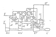
- Figure 1 is a flowsheet representing a gas turbine cycle in accordance with the present invention and comprises a contact type heat exchanging tower (hereinafter called the exchanging tower) intended to allow the compressed air of the compressors to contact the water therein, three regenerators, a heat exchanger (hereinafter called the after-cooler) intended to cool the compressed air which is being used for the contact operation, an inter- cooler, two compressors, and a turbine.
- the exchanging tower a contact type heat exchanging tower
- the after-cooler intended to cool the compressed air which is being used for the contact operation
- an inter- cooler two compressors
- two compressors two compressors
- ambient air (3') is taken in by the first air compressor (AC' 1 ) in which the air undergoes adiabatic compression for admission to the intercooler (lC') through a conduit (4').
- the air after being cooled by the cooling water in conduit (17') in the intercooler which receives water (24') from the exchange tower (EXT') while being replenished by a pressurized water pipe (2'), and then being also cooled by the replenishing water pipe (2') itself, is admitted through a conduit (5') to the second air compressor (AC' 2 ) in which the air, after being subjected to further adiabatic compression, is converted to compressed air which is passed through conduit (6').
- a portion of the compressed air in conduit (6') is, as required, routed to the high temperature regenerator (R' i ) by way of a conduit (8').
- the remaining compressed air is introduced through a conduit (7') to the after-cooler (SR') for precooling and, leaving the after-cooler, is introduced into the exchanging tower by way of a conduit (9').
- the exchanging tower (EXT') is designed to receive water that is used as heat recovering medium in regenerative cycles and has been heated from the regenerator (R' 2 ), the after-cooler (SR'), and the intercooler (IC'), respectively, by way of conduits (22'), (19') and (18').
- This heated water is in this exchanging tower allowed to contact the compressed air in the manner of counterflow so as to produce a compressed air/steam mixture in which the partial pressure of steam is increased for admission to the high temperature regenerator (R' 1 ) through conduit (10').
- the part of the water which has been cooled by the contact operation is routed through a conduit (20') to the after-cooler (SR'), the regenerator (R' 2 ), and the intercooler (IC'), respectively through conduits (23') (21') and (24') and, after being heated at those locations, is recycled to the exchanging tower (ExT').
- the compressed air/steam mixture introduced into the high temperature regenerator (R' i ) performs heat absorption there together with compressed air supplied, as required, directly from the compressor (AC' 2 ) through the conduit (8'), and is admitted to the combustion chamber (CC') by way of a conduit (11').
- To the combustion chamber (CC') is also introduced through a conduit (25') fuel (1') that is preheated by the regenerator (R' 3 ).
- the combustion chamber burns fuel and compressed air to supply combustion gas, heated as required, to the turbine (ET') through a conduit (12').
- the combustion gas undergoes an adiabatic expansion in the expansion turbine (ET') powering the first and the second air compressors (AC' 1 ) and (AC' 2 ) and the load (L') to which the turbine is connected, and are finally discharged as exhaust gas through a conduit (13).
- a portion of the exhaust gases is routed through a conduit (26') to the regenerator (R' 3 ) for preheating the fuel.
- the remaining exhaust gases are passed through a conduit (14') first to the high temperature regenerator (R' 1 ) and then through a conduit (15') to the low temperature regenerator (R' 2 ) in both of which the exhaust gases give off their heat for heat transfer.
- the exhaust gas is discharged as waste gas (27') through a conduit (16').
- the gas after leaving the regenerators, turns to low temperature waste gas.
- the design of a gas turbine should require the additional use of sealing air for the air compressors (AC' 1 ) and (AC' 2 ), and the turbine (ET') and of cooling air to cool the turbine (ET').
- the gas turbine cycle according to the present invention can produce compressed air at low temperature, it is possible to reduce the amount of the compressed air used for cooling the turbine to a larger extent than is possible with conventional gas turbine cycles. This is an additional feature of this invention that serves to further enhance the thermal efficiency of the gas turbine cycle.
- the gas turbine cycle provides not only for heat recovery of the turbine exhaust gas but also for after-cooling of the compressed air for the contact operation by the water which is obtained by the contact between the water and a part of or the whole of the compressed air.
- Various modifications are possible without departing from the principle of the method, for example, the use of fuel as well as water as the cooling medium for intercooling, operation on the principle of a reheat cycle, two stage operation in the exchange tower, and the addition of a condenser to recover water contained in the water gas.
- another exchanging tower in addition to the exchanging tower (EXT' shown in Figure 1) may be employed.
- a portion of the heated water resulting from the heat recovery operation is introduced in this additional exchanging tower at its upper portion and the fuel in a gaseous phase is introduced in the same at its lower portion so that they contact each other in the manner of counterflow.
- the mixture of the gaseous fuel and the steam obtained from this contacting operation is extracted from the top of the additional exchanging tower and it is fed directly or after being used as a heat recovering medium to the combustion chamber CC'.
- the cooled water extracted from the bottom of the additional exchanging tower is recycled as a heat recovering medium.
- the gas turbine of this invention provides a desirable relationship between thermal efficiency and cycle pressure ratio, that is to say, in a higher cycle pressure ratio it provides a lower rate of reduction of the thermal efficiency compared with the conventional gas turbine cycle.
- the advantages are greater in a reheat cycle or at high levels of specific power.
- a desired amount of the compressed air may be by-passed to the high temperature regenerator. It is also necessary to determine the amount of the water which contacts compressed air so as to form a compressed air/steam mixture and is lost by evaporation, which is the amount of water needed to replenish the regenerative cycle.
- the amount of the water normally is between 0.1-0.4 Kg-mole for 1 Kg-mole of the air intake.
- the optimum amount of the water for blending with the compressed air lies in the range of between from 0.1 to 0.2 Kg-mole, or more preferably, between from 0.12 to 0.16 Kg-mole per 1 Kg-mole of the air intake.
- the problem of pressure distribution in the compressors before and after the stage of intercooling may be considered in the light of the intercooling effect to help reduce the compressor driving power.
Landscapes
- Engineering & Computer Science (AREA)
- Chemical & Material Sciences (AREA)
- Combustion & Propulsion (AREA)
- Mechanical Engineering (AREA)
- General Engineering & Computer Science (AREA)
- Engine Equipment That Uses Special Cycles (AREA)
Claims (11)
Applications Claiming Priority (4)
| Application Number | Priority Date | Filing Date | Title |
|---|---|---|---|
| JP19936481A JPS58101228A (ja) | 1981-12-10 | 1981-12-10 | ガスタ−ビンサイクル |
| JP19936281A JPS58101226A (ja) | 1981-12-10 | 1981-12-10 | ガスタ−ビンサイクル |
| JP199362/81 | 1981-12-10 | ||
| JP199364/81 | 1981-12-10 |
Publications (3)
| Publication Number | Publication Date |
|---|---|
| EP0081996A2 EP0081996A2 (fr) | 1983-06-22 |
| EP0081996A3 EP0081996A3 (en) | 1984-07-18 |
| EP0081996B1 true EP0081996B1 (fr) | 1988-10-05 |
Family
ID=26511490
Family Applications (1)
| Application Number | Title | Priority Date | Filing Date |
|---|---|---|---|
| EP82306607A Expired EP0081996B1 (fr) | 1981-12-10 | 1982-12-10 | Cycle de turbine à gaz avec récupération de chaleur |
Country Status (4)
| Country | Link |
|---|---|
| US (2) | US4537023A (fr) |
| EP (1) | EP0081996B1 (fr) |
| CA (1) | CA1218240A (fr) |
| DE (1) | DE3279086D1 (fr) |
Families Citing this family (43)
| Publication number | Priority date | Publication date | Assignee | Title |
|---|---|---|---|---|
| NL191444C (nl) * | 1982-02-16 | 1995-07-04 | Shell Int Research | Werkwijze voor het opwekken van mechanische energie en het genereren van stoom met behulp van een gasturbine. |
| US4829763A (en) * | 1984-02-01 | 1989-05-16 | Fluor Corporation | Process for producing power |
| AU607684B2 (en) * | 1984-02-01 | 1991-03-14 | Fluor Corporation | Process for producing power |
| AU591460B2 (en) * | 1984-02-01 | 1989-12-07 | Fluor Corporation | Process for producing power |
| ZA85528B (en) * | 1984-02-01 | 1986-12-30 | Fluor Corp | Process for producing power |
| BE905234R (fr) * | 1985-11-21 | 1986-12-01 | Fluor Corp | Procede de production d'energie. |
| JPS62203929A (ja) * | 1986-03-04 | 1987-09-08 | Mitsubishi Gas Chem Co Inc | 酸化反応器オフガスからの動力化回収方法 |
| US4753068A (en) * | 1987-01-15 | 1988-06-28 | El Masri Maher A | Gas turbine cycle incorporating simultaneous, parallel, dual-mode heat recovery |
| US5010726A (en) * | 1988-09-28 | 1991-04-30 | Westinghouse Electric Corp. | System and method for efficiently generating power in a solid fuel gas turbine |
| US4991391A (en) * | 1989-01-27 | 1991-02-12 | Westinghouse Electric Corp. | System for cooling in a gas turbine |
| US5582000A (en) * | 1989-02-08 | 1996-12-10 | United Technologies Corporation | Coolable rocket nozzle for a rocket engine |
| US5181376A (en) * | 1990-08-10 | 1993-01-26 | Fluor Corporation | Process and system for producing power |
| US5218815A (en) * | 1991-06-04 | 1993-06-15 | Donlee Technologies, Inc. | Method and apparatus for gas turbine operation using solid fuel |
| EP0589960B1 (fr) * | 1991-06-17 | 1997-01-02 | Electric Power Research Institute, Inc | Centrale electrique utilisant le stockage |
| US5398497A (en) * | 1991-12-02 | 1995-03-21 | Suppes; Galen J. | Method using gas-gas heat exchange with an intermediate direct contact heat exchange fluid |
| US5241816A (en) * | 1991-12-09 | 1993-09-07 | Praxair Technology, Inc. | Gas turbine steam addition |
| CA2093683C (fr) * | 1992-05-14 | 2002-10-15 | William Miller Farrell | Turbine a gaz a refroidissement intermediaire |
| JP3315719B2 (ja) * | 1992-06-03 | 2002-08-19 | 東京電力株式会社 | 化学ループ燃焼方式発電プラントシステム |
| NL9201256A (nl) * | 1992-07-13 | 1994-02-01 | Kema Nv | Steg-inrichting voor het opwekken van elektriciteit met bevochtigd aardgas. |
| US5622044A (en) * | 1992-11-09 | 1997-04-22 | Ormat Industries Ltd. | Apparatus for augmenting power produced from gas turbines |
| JPH0826780B2 (ja) * | 1993-02-26 | 1996-03-21 | 石川島播磨重工業株式会社 | 部分再生式二流体ガスタービン |
| US5347806A (en) * | 1993-04-23 | 1994-09-20 | Cascaded Advanced Turbine Limited Partnership | Cascaded advanced high efficiency multi-shaft reheat turbine with intercooling and recuperation |
| US5406786A (en) * | 1993-07-16 | 1995-04-18 | Air Products And Chemicals, Inc. | Integrated air separation - gas turbine electrical generation process |
| IL110361A (en) * | 1993-07-22 | 2003-03-12 | Ormat Ind Ltd | Method of and apparatus for augmenting power produced by gas turbines |
| US5495709A (en) * | 1994-08-05 | 1996-03-05 | Abb Management Ag | Air reservoir turbine |
| US5961942A (en) * | 1995-06-05 | 1999-10-05 | E. I. Du Pont De Nemours And Company | Effluent gas treatment |
| DE19546726A1 (de) * | 1995-12-14 | 1997-06-19 | Asea Brown Boveri | Quench-Kühler |
| ATE218673T1 (de) * | 1996-07-10 | 2002-06-15 | Vattenfall Ab Publ | Verfahren und vorrichtung zum liefern von mechanischer arbeit und, wenn gewünscht, wärme in einem gasverdampfungsturbinenprozess |
| DE59709403D1 (de) | 1997-07-25 | 2003-04-03 | Alstom Switzerland Ltd | Verfahren zum Betrieb einer Kraftwerksanlage |
| AU2172500A (en) | 1998-12-11 | 2000-06-26 | Allied-Signal Inc. | Power generation system, and heat exchanger and operating method for a power generation system |
| GB9906620D0 (en) * | 1999-03-23 | 1999-05-19 | Rolls Royce Plc | Power generation equipment |
| DE10039246C2 (de) * | 2000-08-11 | 2002-06-13 | Atz Evus | Verfahren zur Umwandlung von thermischer Energie in mechanische Arbeit |
| IL166089A0 (en) * | 2002-07-20 | 2006-01-15 | Idalex Technologies Inc | Evaporative duplex counterheat exchanger |
| US7961835B2 (en) | 2005-08-26 | 2011-06-14 | Keller Michael F | Hybrid integrated energy production process |
| US8601821B2 (en) * | 2007-08-07 | 2013-12-10 | General Electric Company | Method and apparatus for supplying pressure for spray inlet temperature suppressor of gas turbines |
| US8051654B2 (en) * | 2008-01-31 | 2011-11-08 | General Electric Company | Reheat gas and exhaust gas regenerator system for a combined cycle power plant |
| US20110036098A1 (en) * | 2009-08-17 | 2011-02-17 | General Electric Company | Self-regulating cooling water system for intercooled gas turbine engines |
| US9546574B2 (en) * | 2010-12-28 | 2017-01-17 | Rolls-Royce Corporation | Engine liquid injection |
| DE102013017010A1 (de) * | 2013-10-14 | 2015-04-16 | Karl Brotzmann Consulting Gmbh | Stromspeicherung über thermische Speicher und Luftturbine |
| RU2631849C1 (ru) * | 2016-07-14 | 2017-09-26 | Павел Игнатьевич Загуменнов | Силовая установка и парогазогенератор для этой силовой установки (два варианта) |
| RU179513U1 (ru) * | 2017-06-06 | 2018-05-17 | Павел Игнатьевич Загуменнов | Парогазогенератор |
| RU2662748C1 (ru) * | 2017-06-06 | 2018-07-30 | Российская Федерация, От Имени Которой Выступает Министерство Промышленности И Торговли Российской Федерации | Конденсатор с регулированием потока охлаждающей среды |
| US11492964B2 (en) | 2020-11-25 | 2022-11-08 | Michael F. Keller | Integrated supercritical CO2/multiple thermal cycles |
Citations (2)
| Publication number | Priority date | Publication date | Assignee | Title |
|---|---|---|---|---|
| DE665607C (de) * | 1933-11-15 | 1938-09-30 | Michael Martinka Dipl Ing | Verfahren zur Herstellung verdichteter, mit Feuchtigkeit angereicherter Luft und gegebenenfalls Brenngas fuer Brennkraftmaschinen |
| EP0053045A1 (fr) * | 1980-11-25 | 1982-06-02 | Mitsubishi Gas Chemical Company, Inc. | Turbine à gaz régénératrice et son procédé de fonctionnement |
Family Cites Families (17)
| Publication number | Priority date | Publication date | Assignee | Title |
|---|---|---|---|---|
| US2115338A (en) * | 1932-12-15 | 1938-04-26 | Milo Ab | Gas turbine system |
| US2186706A (en) * | 1933-11-14 | 1940-01-09 | Martinka Michael | Combustion engine and a method for the operation thereof |
| DE718197C (de) * | 1938-09-27 | 1942-03-05 | Michael Martinka Dipl Ing | Verfahren zum Betrieb von Brennkraftmaschinen |
| DE717711C (de) * | 1939-04-12 | 1942-02-21 | Michael Martinka Dipl Ing | Arbeitsverfahren fuer Brennkraftturbinen |
| US2602289A (en) * | 1945-05-25 | 1952-07-08 | Rateau Soc | Method and means for propelling a vehicle using normally gaseous fuel as a liquid |
| FR1010954A (fr) * | 1947-12-19 | 1952-06-17 | Rateau Soc | Perfectionnements aux turbomoteurs |
| IT454098A (fr) * | 1948-02-27 | |||
| GB676008A (en) * | 1948-10-11 | 1952-07-23 | Rateau Soc | Improvements in or relating to gas turbine plants |
| CH318979A (fr) * | 1951-01-18 | 1957-01-31 | Zborowski Helmut Von | Installation comprenant une turbomachine |
| US2678532A (en) * | 1951-03-16 | 1954-05-18 | Chemical Foundation Inc | Gas turbine process using two heat sources |
| GB1102572A (en) * | 1964-06-06 | 1968-02-07 | Bristol Siddeley Engines Ltd | Jet propulsion engines |
| CH457039A (de) * | 1967-05-03 | 1968-05-31 | Bbc Brown Boveri & Cie | Gasturbinenanlage mit Wassereinspritzung |
| FR1568871A (fr) * | 1968-01-18 | 1969-05-30 | ||
| US3877218A (en) * | 1971-09-14 | 1975-04-15 | William H Nebgen | Brayton cycle system with refrigerated intake and condensed water injection |
| DE2743830C2 (de) * | 1977-09-29 | 1984-03-22 | Saarbergwerke AG, 6600 Saarbrücken | Verfahren zum Betreiben einer kombinierten Gas-Dampfkraftanlage und Gas-Dampfkraftanlage zur Durchführung des Verfahrens |
| US4418527A (en) * | 1980-04-21 | 1983-12-06 | Schlom Leslie A | Precooler for gas turbines |
| EP0051493A3 (fr) * | 1980-11-05 | 1982-12-01 | Mitsubishi Gas Chemical Company, Inc. | Système de transfert de chaleur pour un cycle de combustion interne ouvert |
-
1982
- 1982-12-09 US US06/448,322 patent/US4537023A/en not_active Expired - Lifetime
- 1982-12-10 EP EP82306607A patent/EP0081996B1/fr not_active Expired
- 1982-12-10 CA CA000417429A patent/CA1218240A/fr not_active Expired
- 1982-12-10 DE DE8282306607T patent/DE3279086D1/de not_active Expired
-
1985
- 1985-06-13 US US06/744,238 patent/US4610137A/en not_active Expired - Lifetime
Patent Citations (2)
| Publication number | Priority date | Publication date | Assignee | Title |
|---|---|---|---|---|
| DE665607C (de) * | 1933-11-15 | 1938-09-30 | Michael Martinka Dipl Ing | Verfahren zur Herstellung verdichteter, mit Feuchtigkeit angereicherter Luft und gegebenenfalls Brenngas fuer Brennkraftmaschinen |
| EP0053045A1 (fr) * | 1980-11-25 | 1982-06-02 | Mitsubishi Gas Chemical Company, Inc. | Turbine à gaz régénératrice et son procédé de fonctionnement |
Also Published As
| Publication number | Publication date |
|---|---|
| EP0081996A2 (fr) | 1983-06-22 |
| DE3279086D1 (en) | 1988-11-10 |
| US4537023A (en) | 1985-08-27 |
| EP0081996A3 (en) | 1984-07-18 |
| CA1218240A (fr) | 1987-02-24 |
| US4610137A (en) | 1986-09-09 |
Similar Documents
| Publication | Publication Date | Title |
|---|---|---|
| EP0081996B1 (fr) | Cycle de turbine à gaz avec récupération de chaleur | |
| US4829763A (en) | Process for producing power | |
| US4128994A (en) | Regenerative parallel compound dual-fluid heat engine | |
| US4248039A (en) | Regenerative parallel compound dual fluid heat engine | |
| US3757517A (en) | Power-generating plant using a combined gas- and steam-turbine cycle | |
| US4653268A (en) | Regenerative gas turbine cycle | |
| CA1259496A (fr) | Methode de production d'energie | |
| US6848249B2 (en) | Coleman regenerative engine with exhaust gas water extraction | |
| CA1210376A (fr) | Methode et dispositif de compression de gaz | |
| EP0828925A1 (fr) | Centrale thermique a cycle mixte fonctionnant au gaz naturel liquefie et turbine a gaz fonctionnant au gaz naturel liquefie | |
| US5181376A (en) | Process and system for producing power | |
| CN112780409A (zh) | 一种采用连续爆轰的燃机与液态压缩空气储能耦合系统及方法 | |
| US5241816A (en) | Gas turbine steam addition | |
| US4227374A (en) | Methods and means for storing energy | |
| WO2002014662A1 (fr) | Procede d'utilisation de l'energie de dilatation de gaz et installation d'utilisation de l'energie destinee a la mise en oeuvre de ce procede | |
| CN214741682U (zh) | 一种采用连续爆轰的燃机与液态压缩空气储能耦合系统 | |
| JPH09250360A (ja) | エネルギー貯蔵型ガスタービン発電システム | |
| CN118745947A (zh) | 一种与火电机组热电耦合的液态空气储能系统的运行方法 | |
| CN100389251C (zh) | 一种燃气动力循环系统及循环方法 | |
| JPH0354327A (ja) | 余剰電力利用システム | |
| JP2004150685A (ja) | 窒素製造設備及びタービン発電設備 | |
| JPH0131012B2 (fr) | ||
| CN117722819A (zh) | 一种自平衡式耦合lng冷能的新型液化空气储能系统 | |
| JP2000120404A (ja) | 複合発電プラント | |
| JPH0131013B2 (fr) |
Legal Events
| Date | Code | Title | Description |
|---|---|---|---|
| PUAI | Public reference made under article 153(3) epc to a published international application that has entered the european phase |
Free format text: ORIGINAL CODE: 0009012 |
|
| AK | Designated contracting states |
Designated state(s): DE FR GB IT |
|
| PUAL | Search report despatched |
Free format text: ORIGINAL CODE: 0009013 |
|
| AK | Designated contracting states |
Designated state(s): DE FR GB IT |
|
| 17P | Request for examination filed |
Effective date: 19840912 |
|
| GRAA | (expected) grant |
Free format text: ORIGINAL CODE: 0009210 |
|
| ITF | It: translation for a ep patent filed | ||
| AK | Designated contracting states |
Kind code of ref document: B1 Designated state(s): DE FR GB IT |
|
| REF | Corresponds to: |
Ref document number: 3279086 Country of ref document: DE Date of ref document: 19881110 |
|
| ET | Fr: translation filed | ||
| PLBE | No opposition filed within time limit |
Free format text: ORIGINAL CODE: 0009261 |
|
| STAA | Information on the status of an ep patent application or granted ep patent |
Free format text: STATUS: NO OPPOSITION FILED WITHIN TIME LIMIT |
|
| 26N | No opposition filed | ||
| ITTA | It: last paid annual fee | ||
| PGFP | Annual fee paid to national office [announced via postgrant information from national office to epo] |
Ref country code: GB Payment date: 19971201 Year of fee payment: 16 |
|
| PGFP | Annual fee paid to national office [announced via postgrant information from national office to epo] |
Ref country code: FR Payment date: 19971209 Year of fee payment: 16 |
|
| PGFP | Annual fee paid to national office [announced via postgrant information from national office to epo] |
Ref country code: DE Payment date: 19971222 Year of fee payment: 16 |
|
| PG25 | Lapsed in a contracting state [announced via postgrant information from national office to epo] |
Ref country code: GB Free format text: LAPSE BECAUSE OF NON-PAYMENT OF DUE FEES Effective date: 19981210 |
|
| GBPC | Gb: european patent ceased through non-payment of renewal fee |
Effective date: 19981210 |
|
| PG25 | Lapsed in a contracting state [announced via postgrant information from national office to epo] |
Ref country code: FR Free format text: LAPSE BECAUSE OF NON-PAYMENT OF DUE FEES Effective date: 19990831 |
|
| REG | Reference to a national code |
Ref country code: FR Ref legal event code: ST |
|
| PG25 | Lapsed in a contracting state [announced via postgrant information from national office to epo] |
Ref country code: DE Free format text: LAPSE BECAUSE OF NON-PAYMENT OF DUE FEES Effective date: 19991001 |