EP0082051A2 - Verfahren zur Herstellung einer Kühlvorrichtung - Google Patents
Verfahren zur Herstellung einer Kühlvorrichtung Download PDFInfo
- Publication number
- EP0082051A2 EP0082051A2 EP82402215A EP82402215A EP0082051A2 EP 0082051 A2 EP0082051 A2 EP 0082051A2 EP 82402215 A EP82402215 A EP 82402215A EP 82402215 A EP82402215 A EP 82402215A EP 0082051 A2 EP0082051 A2 EP 0082051A2
- Authority
- EP
- European Patent Office
- Prior art keywords
- turns
- base support
- mandrels
- support
- frame
- Prior art date
- Legal status (The legal status is an assumption and is not a legal conclusion. Google has not performed a legal analysis and makes no representation as to the accuracy of the status listed.)
- Granted
Links
Images

Classifications
-
- F—MECHANICAL ENGINEERING; LIGHTING; HEATING; WEAPONS; BLASTING
- F28—HEAT EXCHANGE IN GENERAL
- F28F—DETAILS OF HEAT-EXCHANGE AND HEAT-TRANSFER APPARATUS, OF GENERAL APPLICATION
- F28F3/00—Plate-like or laminated elements; Assemblies of plate-like or laminated elements
- F28F3/02—Elements or assemblies thereof with means for increasing heat-transfer area, e.g. with fins, with recesses, with corrugations
- F28F3/022—Elements or assemblies thereof with means for increasing heat-transfer area, e.g. with fins, with recesses, with corrugations the means being wires or pins
Definitions
- the present invention relates to a method for producing a cooling device with filiform elements.
- the cooling device obtained by this process ensures good thermal coupling between a member to be cooled and the ambient environment and applies in particular to electrical components with high heat dissipation.
- cooling devices are associated with a forced air generator which increases cooling by forced convection.
- the cooling of a traveling wave tube is a typical example of an application using such means.
- the known cooling devices used for such applications are generally so-called "studded" radiators and include a flat base support on which numerous small cylindrical elements are arranged perpendicular to this support.
- alloys with good thermal conductivity generally have poor flowability, which leads to a reduction in the length of the pins and their distribution density, thereby limiting the contact surface with the cooling fluid.
- the molten metal tends to cool before reaching the bottom of the mold cavities if they are deep and of small section; moreover, during the demoulding, certain pins break and remain inside the mold.
- the need to be able to demold limits the forms that a radiator can have, the base of which is, therefore, generally planar, the pins being perpendicular to this base. To these drawbacks are added the high cost of a mold and the difficulties encountered in obtaining modifications of the characteristics of the radiator.
- Milling in the mass introduces a significant loss of material and requires a relatively long execution time.
- the pins have tendency to bend in the direction that the tool attacks metal; to limit this deflection, the pins must be short, of large section and consequently few in number, which limits the performance of the device.
- the milling technique is also ill-suited to mass production.
- each spike is placed in a blind hole made in the support, the pins and the support being previously tinned. The whole is brought to the melting temperature of the tin and then cooled. The pins are thus welded to the support.
- the assembly technique requires a long execution time and is not compatible with the requirements of mass production.
- the invention proposes a production method which makes it possible to overcome the aforementioned drawbacks of the known art while improving the performance level of the pin radiators.
- the method according to the invention proposes to replace the pins of the known art with filiform elements, generally turns, made of wire of good thermal conductivity and welded on a base support.
- the invention also relates to the cooling device obtained by this process.
- FIG. 1 illustrates an example of a radiator with pins according to the known art, as it could be obtained by a molding or assembly technique.
- the pins 2 secured to a flat base support 1 are, for the clarity of the figure shown with a low density of distribution.
- the edge to edge distance between two pins and the diameter of said pins are of the same order of magnitude.
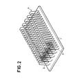
- FIG. 2 represents a first variant of the device obtained by the method according to the invention.
- Wire of good thermal conductivity in this example tinned copper wire, is wound with non-contiguous turns on a mandrel with rectangular section.
- the rectangle constituting the section of the mandrel has, in this preferred variant, short sides of length substantially greater than the diameter of the wire and long sides of length equal to approximately fifteen times said diameter. For the clarity of the drawing these proportions are not exactly respected.
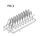
- FIG. 3 represents a second variant of the device obtained by the method according to the invention.
- the sets 5 of turns 6 are obtained by winding tinned copper wire on mandrels of triangular section.
- Each set 5, arranged parallel to the long sides of the support 1, has its turns 6 partially engaged between the turns of the sets 5 which are adjacent to it.
- For each of the turns 6, one side of the triangle ensures contact over its entire length with the base support 1.
- Each turn is located in a plane perpendicular to the support 1 and fixed to the latter by a filler metal with a low melting point (tin, lead-tin alloy, etc.).
- the coils being nested, the triangular section mandrels must be removed before the assemblies 5 are placed on the support 1.
- the assemblies 5 are placed, in the nested position, in the cavities a positioning support before being brought closer to the base support 1.
- the positioning support is removed after fixing the turns 6 on the support 1.
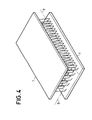
- FIG. 4 presents a step in a method allowing two cooling devices to be produced simultaneously.
- a first device is produced according to the method described for the first variant corresponding to FIG. 2.
- a second base support 7 bearing on the other short side of the turns is superimposed on the first base support 1.
- the second support 7 is subjected to a thermal cycle which makes it integral with the turns by melting a filler metal.
- the mandrels are eliminated and FIG. 4 illustrates the device obtained at this stage.
- the space between supports 1 and 7 comprising the turns is filled with wax or another product which can be solidified at room temperature. After the wax has hardened, the assembly is cut along a plane parallel to the supports 1 and 7, located midway between these two supports and represented in FIG. 4 by the two orthogonal axes 8 and 9.
- the wax is eliminated by temperature rise and the two cooling devices obtained constitute so-called "pin" coolers.
- the invention is not limited to the three variant embodiments which have just been described. It is indeed possible to act separately or in combinations on numerous parameters such as the nature of the wire, the shape and the value of its section, the shape and the size of the turns; the turns can, after fixing, be opened and the filiform elements take any desired configuration.
- the density of distribution of the filiform elements can be modulated by varying the pitch of the turns, the distance between the sets of turns, the dimension of the turns and the cross section of the wire of each of the sets of turns in order to optimize the performances in each application case.
- the material, shape and dimensions of the support can also contribute to this optimization.
- the manufacturing method of the cooling device described above has the advantages of not requiring any elaborate and expensive tooling and of making it possible to obtain more efficient radiators (longer, thinner, more numerous filiform elements) than by known techniques. .
- this process is suitable for the installation of filiform elements on supports of any shape (not necessarily planar) and easily lends itself to the production of radiators made "on demand" (non-standardized products). Finally, it easily lends itself to mass production and makes it possible to reduce the cost of cooling devices.
Landscapes
- Engineering & Computer Science (AREA)
- Physics & Mathematics (AREA)
- Thermal Sciences (AREA)
- Mechanical Engineering (AREA)
- General Engineering & Computer Science (AREA)
- Cooling Or The Like Of Semiconductors Or Solid State Devices (AREA)
- Wire Processing (AREA)
- General Induction Heating (AREA)
- Cooling Or The Like Of Electrical Apparatus (AREA)
- Thermistors And Varistors (AREA)
- Apparatuses And Processes For Manufacturing Resistors (AREA)
- Heating, Cooling, Or Curing Plastics Or The Like In General (AREA)
- Manufacture Or Reproduction Of Printing Formes (AREA)
Priority Applications (1)
| Application Number | Priority Date | Filing Date | Title |
|---|---|---|---|
| AT82402215T ATE24818T1 (de) | 1981-12-11 | 1982-12-03 | Verfahren zur herstellung einer kuehlvorrichtung. |
Applications Claiming Priority (2)
| Application Number | Priority Date | Filing Date | Title |
|---|---|---|---|
| FR8123212A FR2518357A1 (fr) | 1981-12-11 | 1981-12-11 | Procede de realisation d'un dispositif de refroidissement a elements filiformes pour composant electronique et dispositif de refroidissement ainsi obtenu |
| FR8123212 | 1981-12-11 |
Publications (3)
| Publication Number | Publication Date |
|---|---|
| EP0082051A2 true EP0082051A2 (de) | 1983-06-22 |
| EP0082051A3 EP0082051A3 (en) | 1984-01-11 |
| EP0082051B1 EP0082051B1 (de) | 1987-01-07 |
Family
ID=9264935
Family Applications (1)
| Application Number | Title | Priority Date | Filing Date |
|---|---|---|---|
| EP82402215A Expired EP0082051B1 (de) | 1981-12-11 | 1982-12-03 | Verfahren zur Herstellung einer Kühlvorrichtung |
Country Status (4)
| Country | Link |
|---|---|
| EP (1) | EP0082051B1 (de) |
| AT (1) | ATE24818T1 (de) |
| DE (1) | DE3275053D1 (de) |
| FR (1) | FR2518357A1 (de) |
Cited By (5)
| Publication number | Priority date | Publication date | Assignee | Title |
|---|---|---|---|---|
| US5212625A (en) * | 1988-12-01 | 1993-05-18 | Akzo Nv | Semiconductor module having projecting cooling fin groups |
| EP0542478A1 (de) * | 1991-11-12 | 1993-05-19 | AT&T Corp. | Wärmesenke mit Stiften und Strömungsverbesserung |
| FR2913765A1 (fr) * | 2007-03-16 | 2008-09-19 | Pierre Vironneau | Nappe de circulation de fluide, procede pour realiser une telle nappe et utilisation de telles nappes pour la realisation d'un echangeur thermique |
| NL2019792B1 (en) * | 2017-10-24 | 2019-04-29 | Micro Turbine Tech B V | Heat exchanger comprising a stack of cells and method of manufacturing such a heat exchanger |
| SE1730353A1 (sv) * | 2017-12-28 | 2019-06-29 | Andersson Inge | Kylanordning |
Families Citing this family (2)
| Publication number | Priority date | Publication date | Assignee | Title |
|---|---|---|---|---|
| DE19623677C2 (de) * | 1996-06-14 | 1999-09-16 | Knuerr Mechanik Ag | Geräteschrank für elektrische und elektronische Systeme |
| DE10140328B4 (de) * | 2001-08-16 | 2006-02-02 | Siemens Ag | Kühlanordnung zur Kühlung elektronischer Bauelemente |
Family Cites Families (4)
| Publication number | Priority date | Publication date | Assignee | Title |
|---|---|---|---|---|
| GB692885A (en) * | 1949-12-28 | 1953-06-17 | Brown Fintube Co | Improvements in the manufacture of heat exchangers |
| US2879041A (en) * | 1956-10-15 | 1959-03-24 | Rca Corp | Heat radiator |
| DE1132883B (de) * | 1957-01-30 | 1962-07-12 | Franciscus Roffelsen | Verfahren zum Herstellung von Waermeaustauschelementen |
| FR1511618A (fr) * | 1966-12-19 | 1968-02-02 | Chausson Usines Sa | Procédé pour la fabrication de dissipateurs de chaleur du type à fils et dissipateur en résultant |
-
1981
- 1981-12-11 FR FR8123212A patent/FR2518357A1/fr active Granted
-
1982
- 1982-12-03 EP EP82402215A patent/EP0082051B1/de not_active Expired
- 1982-12-03 AT AT82402215T patent/ATE24818T1/de not_active IP Right Cessation
- 1982-12-03 DE DE8282402215T patent/DE3275053D1/de not_active Expired
Cited By (8)
| Publication number | Priority date | Publication date | Assignee | Title |
|---|---|---|---|---|
| US5212625A (en) * | 1988-12-01 | 1993-05-18 | Akzo Nv | Semiconductor module having projecting cooling fin groups |
| EP0542478A1 (de) * | 1991-11-12 | 1993-05-19 | AT&T Corp. | Wärmesenke mit Stiften und Strömungsverbesserung |
| FR2913765A1 (fr) * | 2007-03-16 | 2008-09-19 | Pierre Vironneau | Nappe de circulation de fluide, procede pour realiser une telle nappe et utilisation de telles nappes pour la realisation d'un echangeur thermique |
| WO2008132329A3 (fr) * | 2007-03-16 | 2008-12-31 | Pierre Vironneau | Nappe de circulation de fluide, procédé pour réaliser une telle nappe et échangeur thermique comportant une telle nappe |
| NL2019792B1 (en) * | 2017-10-24 | 2019-04-29 | Micro Turbine Tech B V | Heat exchanger comprising a stack of cells and method of manufacturing such a heat exchanger |
| WO2019083361A1 (en) * | 2017-10-24 | 2019-05-02 | Micro Turbine Technology B.V. | HEAT EXCHANGER WITH CELL STACK |
| US11614284B2 (en) | 2017-10-24 | 2023-03-28 | Micro Turbine Technology B.V. | Heat exchanger comprising a stack of cells |
| SE1730353A1 (sv) * | 2017-12-28 | 2019-06-29 | Andersson Inge | Kylanordning |
Also Published As
| Publication number | Publication date |
|---|---|
| EP0082051A3 (en) | 1984-01-11 |
| EP0082051B1 (de) | 1987-01-07 |
| FR2518357A1 (fr) | 1983-06-17 |
| ATE24818T1 (de) | 1987-01-15 |
| DE3275053D1 (en) | 1987-02-12 |
| FR2518357B3 (de) | 1984-12-14 |
Similar Documents
| Publication | Publication Date | Title |
|---|---|---|
| EP0082051B1 (de) | Verfahren zur Herstellung einer Kühlvorrichtung | |
| EP4338257A1 (de) | Statorkörper für eine elektrische axialflussmaschine | |
| WO2023020863A1 (fr) | Procédé d'assemblage d'un corps de stator pour machine électrique à flux axial | |
| EP4331081A1 (de) | Stator für eine axialflussmaschine und verfahren zur herstellung eines solchen stators | |
| EP0883181A1 (de) | Halbleiteranordnung und Verfahren zum Verbinden von internen Massedrähten mit einer solchen Anordnung | |
| EP1452793B1 (de) | Ausrüstungshalterung und ihr Formverfahren | |
| FR2554190A1 (fr) | Disque elastique, notamment pour embrayages, procede pour le fabriquer et dispositif pour la mise en oeuvre du procede | |
| EP0040163A1 (de) | Verfahren zur Herstellung eines Stirnkollektors für elektrische Motoren | |
| EP0624921B1 (de) | Elektrische Anschlussvorrichtung und zugehöriges Herstellungsverfahren | |
| EP4690432A1 (de) | Bauteil aus smc (weichmagnetverbund) oder um die zähne einer elektrischen maschine angebrachtem ferritmaterial | |
| EP0391798B1 (de) | Temperatursensor mit Thermistor und Verfahren zur dessen Herstellung | |
| WO2016009137A1 (fr) | Procede de realisation d'un stator bobine de machine electrique tournante | |
| BE1004684A6 (fr) | Enceinte cylindrique de grand diametre destinee a recevoir des organes devant etre refroidis. | |
| FR2532789A1 (fr) | Collecteur de machine electique tournante, et son procede de fabrication | |
| EP1473503A1 (de) | Gewellten Schlauch mit zumindest einem metallischen Verstärkungsring und Verfahren zu dessen Herstellung. | |
| EP4192634A1 (de) | Verfahren zur herstellung eines lötdrahtes und auf diese weise hergestellter lötdraht | |
| FR2846806A1 (fr) | Procede de fabrication de conducteurs electriques en forme d'epingles en u, dispositif pour la mise en oeuvre de ce procede et conducteurs ainsi obtenus | |
| WO2018096051A1 (fr) | Roue polaire d'inducteur de machine électrique tournante | |
| FR2812444A1 (fr) | Procede de realisation d'un solenoide a caracteristiques variables le long de son axe | |
| FR3147060A1 (fr) | Procede de fabrication d’un rotor a cage d’ecureuil pour une machine electrique | |
| FR2505548A1 (fr) | Connexion en forme d'epingle pour composant electrique muni de deux zones de contact et son utilisation pour la connexion dudit composant | |
| FR3157719A1 (fr) | Procédé de bobinage in situ et ex situ pour machine électrique, et machine électrique associée | |
| EP4070441A1 (de) | Vorrichtung zum halten von zu verschweissenden elektrischen leitern | |
| EP0581684A1 (de) | Wärmetauscher mit gelöteten Rohren und Verfahren zur dessen Herstellung | |
| FR2549292A1 (fr) | Procede de montage de diode |
Legal Events
| Date | Code | Title | Description |
|---|---|---|---|
| PUAI | Public reference made under article 153(3) epc to a published international application that has entered the european phase |
Free format text: ORIGINAL CODE: 0009012 |
|
| AK | Designated contracting states |
Designated state(s): AT BE CH DE FR GB IT LI NL SE |
|
| PUAL | Search report despatched |
Free format text: ORIGINAL CODE: 0009013 |
|
| AK | Designated contracting states |
Designated state(s): AT BE CH DE FR GB IT LI NL SE |
|
| 17P | Request for examination filed |
Effective date: 19840615 |
|
| GRAA | (expected) grant |
Free format text: ORIGINAL CODE: 0009210 |
|
| AK | Designated contracting states |
Kind code of ref document: B1 Designated state(s): AT BE CH DE FR GB IT LI NL SE |
|
| REF | Corresponds to: |
Ref document number: 24818 Country of ref document: AT Date of ref document: 19870115 Kind code of ref document: T |
|
| REF | Corresponds to: |
Ref document number: 3275053 Country of ref document: DE Date of ref document: 19870212 |
|
| ITF | It: translation for a ep patent filed | ||
| PLBE | No opposition filed within time limit |
Free format text: ORIGINAL CODE: 0009261 |
|
| STAA | Information on the status of an ep patent application or granted ep patent |
Free format text: STATUS: NO OPPOSITION FILED WITHIN TIME LIMIT |
|
| 26N | No opposition filed | ||
| PGFP | Annual fee paid to national office [announced via postgrant information from national office to epo] |
Ref country code: NL Payment date: 19911231 Year of fee payment: 10 |
|
| PGFP | Annual fee paid to national office [announced via postgrant information from national office to epo] |
Ref country code: CH Payment date: 19920917 Year of fee payment: 11 |
|
| PGFP | Annual fee paid to national office [announced via postgrant information from national office to epo] |
Ref country code: SE Payment date: 19920923 Year of fee payment: 11 |
|
| PGFP | Annual fee paid to national office [announced via postgrant information from national office to epo] |
Ref country code: FR Payment date: 19920930 Year of fee payment: 11 |
|
| PGFP | Annual fee paid to national office [announced via postgrant information from national office to epo] |
Ref country code: BE Payment date: 19921001 Year of fee payment: 11 |
|
| PGFP | Annual fee paid to national office [announced via postgrant information from national office to epo] |
Ref country code: DE Payment date: 19921016 Year of fee payment: 11 |
|
| PGFP | Annual fee paid to national office [announced via postgrant information from national office to epo] |
Ref country code: GB Payment date: 19921020 Year of fee payment: 11 |
|
| PGFP | Annual fee paid to national office [announced via postgrant information from national office to epo] |
Ref country code: AT Payment date: 19921030 Year of fee payment: 11 |
|
| ITTA | It: last paid annual fee | ||
| PG25 | Lapsed in a contracting state [announced via postgrant information from national office to epo] |
Ref country code: NL Effective date: 19930701 |
|
| NLV4 | Nl: lapsed or anulled due to non-payment of the annual fee | ||
| PG25 | Lapsed in a contracting state [announced via postgrant information from national office to epo] |
Ref country code: GB Effective date: 19931203 Ref country code: AT Effective date: 19931203 |
|
| PG25 | Lapsed in a contracting state [announced via postgrant information from national office to epo] |
Ref country code: SE Effective date: 19931204 |
|
| PG25 | Lapsed in a contracting state [announced via postgrant information from national office to epo] |
Ref country code: LI Effective date: 19931231 Ref country code: CH Effective date: 19931231 Ref country code: BE Effective date: 19931231 |
|
| BERE | Be: lapsed |
Owner name: THOMSON-CSF Effective date: 19931231 |
|
| GBPC | Gb: european patent ceased through non-payment of renewal fee |
Effective date: 19931203 |
|
| PG25 | Lapsed in a contracting state [announced via postgrant information from national office to epo] |
Ref country code: FR Effective date: 19940831 |
|
| REG | Reference to a national code |
Ref country code: CH Ref legal event code: PL |
|
| PG25 | Lapsed in a contracting state [announced via postgrant information from national office to epo] |
Ref country code: DE Effective date: 19940901 |
|
| REG | Reference to a national code |
Ref country code: FR Ref legal event code: ST |
|
| EUG | Se: european patent has lapsed |
Ref document number: 82402215.6 Effective date: 19940710 |