EP0082143B1 - Four de fusion et procédé pour contrôler la fusion - Google Patents
Four de fusion et procédé pour contrôler la fusion Download PDFInfo
- Publication number
- EP0082143B1 EP0082143B1 EP81902096A EP81902096A EP0082143B1 EP 0082143 B1 EP0082143 B1 EP 0082143B1 EP 81902096 A EP81902096 A EP 81902096A EP 81902096 A EP81902096 A EP 81902096A EP 0082143 B1 EP0082143 B1 EP 0082143B1
- Authority
- EP
- European Patent Office
- Prior art keywords
- orifice
- product
- primary
- control electrode
- nozzle
- Prior art date
- Legal status (The legal status is an assumption and is not a legal conclusion. Google has not performed a legal analysis and makes no representation as to the accuracy of the status listed.)
- Expired
Links
- 238000002844 melting Methods 0.000 title claims description 22
- 230000008018 melting Effects 0.000 title claims description 22
- 238000000034 method Methods 0.000 title claims description 18
- 239000002826 coolant Substances 0.000 claims description 27
- 230000004044 response Effects 0.000 claims description 16
- 230000001276 controlling effect Effects 0.000 claims description 13
- 238000001816 cooling Methods 0.000 claims description 12
- 230000001105 regulatory effect Effects 0.000 claims description 3
- 239000010881 fly ash Substances 0.000 abstract description 20
- 239000011490 mineral wool Substances 0.000 abstract description 11
- 238000004519 manufacturing process Methods 0.000 abstract description 4
- 230000001419 dependent effect Effects 0.000 abstract description 2
- 239000011521 glass Substances 0.000 description 9
- IJGRMHOSHXDMSA-UHFFFAOYSA-N Atomic nitrogen Chemical compound N#N IJGRMHOSHXDMSA-UHFFFAOYSA-N 0.000 description 6
- 239000012530 fluid Substances 0.000 description 5
- XEEYBQQBJWHFJM-UHFFFAOYSA-N Iron Chemical compound [Fe] XEEYBQQBJWHFJM-UHFFFAOYSA-N 0.000 description 4
- ZOKXTWBITQBERF-UHFFFAOYSA-N Molybdenum Chemical compound [Mo] ZOKXTWBITQBERF-UHFFFAOYSA-N 0.000 description 4
- 238000010586 diagram Methods 0.000 description 4
- 229910052750 molybdenum Inorganic materials 0.000 description 4
- 239000011733 molybdenum Substances 0.000 description 4
- OKTJSMMVPCPJKN-UHFFFAOYSA-N Carbon Chemical compound [C] OKTJSMMVPCPJKN-UHFFFAOYSA-N 0.000 description 3
- 239000010439 graphite Substances 0.000 description 3
- 229910002804 graphite Inorganic materials 0.000 description 3
- 239000000463 material Substances 0.000 description 3
- 229910052757 nitrogen Inorganic materials 0.000 description 3
- 238000006467 substitution reaction Methods 0.000 description 3
- RYGMFSIKBFXOCR-UHFFFAOYSA-N Copper Chemical compound [Cu] RYGMFSIKBFXOCR-UHFFFAOYSA-N 0.000 description 2
- 229910052802 copper Inorganic materials 0.000 description 2
- 239000010949 copper Substances 0.000 description 2
- 230000003247 decreasing effect Effects 0.000 description 2
- 238000010438 heat treatment Methods 0.000 description 2
- 229910052500 inorganic mineral Inorganic materials 0.000 description 2
- 229910052742 iron Inorganic materials 0.000 description 2
- 230000007246 mechanism Effects 0.000 description 2
- 238000010309 melting process Methods 0.000 description 2
- 239000011707 mineral Substances 0.000 description 2
- 230000003647 oxidation Effects 0.000 description 2
- 238000007254 oxidation reaction Methods 0.000 description 2
- 239000007921 spray Substances 0.000 description 2
- 229910001220 stainless steel Inorganic materials 0.000 description 2
- 239000010935 stainless steel Substances 0.000 description 2
- XLYOFNOQVPJJNP-UHFFFAOYSA-N water Substances O XLYOFNOQVPJJNP-UHFFFAOYSA-N 0.000 description 2
- 230000009471 action Effects 0.000 description 1
- PNEYBMLMFCGWSK-UHFFFAOYSA-N aluminium oxide Inorganic materials [O-2].[O-2].[O-2].[Al+3].[Al+3] PNEYBMLMFCGWSK-UHFFFAOYSA-N 0.000 description 1
- 238000007664 blowing Methods 0.000 description 1
- 238000009529 body temperature measurement Methods 0.000 description 1
- 239000004568 cement Substances 0.000 description 1
- 238000006243 chemical reaction Methods 0.000 description 1
- 239000010883 coal ash Substances 0.000 description 1
- 239000012141 concentrate Substances 0.000 description 1
- 230000000694 effects Effects 0.000 description 1
- 239000000835 fiber Substances 0.000 description 1
- 239000002657 fibrous material Substances 0.000 description 1
- 238000007710 freezing Methods 0.000 description 1
- 230000008014 freezing Effects 0.000 description 1
- 238000005816 glass manufacturing process Methods 0.000 description 1
- 239000011261 inert gas Substances 0.000 description 1
- 238000003780 insertion Methods 0.000 description 1
- 230000037431 insertion Effects 0.000 description 1
- 238000009413 insulation Methods 0.000 description 1
- 239000012212 insulator Substances 0.000 description 1
- 238000002955 isolation Methods 0.000 description 1
- 239000007788 liquid Substances 0.000 description 1
- 238000005259 measurement Methods 0.000 description 1
- 239000000155 melt Substances 0.000 description 1
- 239000006060 molten glass Substances 0.000 description 1
- 230000008569 process Effects 0.000 description 1
- 239000011819 refractory material Substances 0.000 description 1
- 239000011435 rock Substances 0.000 description 1
- 239000007787 solid Substances 0.000 description 1
Images


Classifications
-
- C—CHEMISTRY; METALLURGY
- C03—GLASS; MINERAL OR SLAG WOOL
- C03B—MANUFACTURE, SHAPING, OR SUPPLEMENTARY PROCESSES
- C03B5/00—Melting in furnaces; Furnaces so far as specially adapted for glass manufacture
- C03B5/02—Melting in furnaces; Furnaces so far as specially adapted for glass manufacture in electric furnaces, e.g. by dielectric heating
- C03B5/027—Melting in furnaces; Furnaces so far as specially adapted for glass manufacture in electric furnaces, e.g. by dielectric heating by passing an electric current between electrodes immersed in the glass bath, i.e. by direct resistance heating
- C03B5/0275—Shaft furnaces
-
- H—ELECTRICITY
- H05—ELECTRIC TECHNIQUES NOT OTHERWISE PROVIDED FOR
- H05B—ELECTRIC HEATING; ELECTRIC LIGHT SOURCES NOT OTHERWISE PROVIDED FOR; CIRCUIT ARRANGEMENTS FOR ELECTRIC LIGHT SOURCES, IN GENERAL
- H05B3/00—Ohmic-resistance heating
- H05B3/0019—Circuit arrangements
- H05B3/0023—Circuit arrangements for heating by passing the current directly across the material to be heated
-
- H—ELECTRICITY
- H05—ELECTRIC TECHNIQUES NOT OTHERWISE PROVIDED FOR
- H05B—ELECTRIC HEATING; ELECTRIC LIGHT SOURCES NOT OTHERWISE PROVIDED FOR; CIRCUIT ARRANGEMENTS FOR ELECTRIC LIGHT SOURCES, IN GENERAL
- H05B3/00—Ohmic-resistance heating
- H05B3/02—Details
- H05B3/03—Electrodes
Definitions
- the present invention relates to a melting furnace suitable for use in converting fly ash into mineral wool and to a method for controlling the melting.
- Mineral wool is a fine fibrous "wool-like" material, typically made by blowing a small stream of molten rock or similar material, such as coal ash, with a jet or stream of fluid. The action of the jet of fluid blows the mineral stream into fine fibrous material which hardens before the fibers reach the floor.
- fly ash typically melts and pours at around 2265 degrees Celsius. However, at this temperature, the fly ash is a gummy mass, whereas at 2315 degrees Celsius the fly ash flows like water. Accordingly, it is essential that any furnace used to melt fly ash for the production of mineral wool have the capacity to control the temperature of the fly ash to precise tolerances, on the order of 5 to 10 degrees Celsius.
- US-A-2,817,695 discloses an electronic furnace and electrode structure designed for the melting of refractory materials such as mineral wool.
- US-A-2,817,695 employs three main electrodes spaced 120 degrees from one another in a plane.
- a nozzle assembly is moveably positioned along a line perpendicular to the plane of the main electrodes at the center point of three electrodes. The nozzle assembly is cooled below oxidation temperature by coolant flow in a nozzle support assembly.
- US-A-2,817,695 recognizes the need to provide accurate temperature control and attempts to accomplish this control by cooling the nozzle assembly and by supplying heat to the nozzle in accordance with temperature measurement of melted product passing through the nozzle assembly.
- US-A-2,817,695 suggests that one way of achieving the requisite control is to apply an electrical potential between the nozzle and a selected one of the main electrodes to effect resistive heating of the melted product at the nozzle.
- US-A-2,817,695 provides no teaching of how the suggested resistive heating of the melted product adjacent the nozzle is to be accomplished. Instead, US-A-2,817,695 concentrates on the structure of coolant passages in the nozzle assembly.
- US-A-3,147,328 discloses an electric glass making furnace which employs: three primary electrodes angularly spaced 120 degrees apart in a plane; a first conductive disc positioned along a line perpendicular to the plane of the main electrodes and which passes through the center of the three primary electrodes, and with the first disc having a passageway through which melted glass may pass out of the vessel; a plurality of auxiliary starting electrodes located above the plane of the three primary electrodes and moveably positioned adjacent the opening of the passageway in the first disc; and a second disc moveably positioned along the above-mentioned line of the first disc to form a slot between the first and second discs which slot is substantially on the same plane as the median plane of the primary electrodes.
- the starting electrodes are moved together three centimeters from each other adjacent the opening of the passageway in the first disc, and are electrically energized to melt glass adjacent the first disc.
- the glass between the starting electrodes is also heated with a blow pipe.
- the starting electrodes are withdrawn as the glass begins to melt and the primary electrodes are energized.
- the second disc is brought into position above the first disc and is also supplied with electrical energy.
- US-A-3,147,328 recognizes that the hottest region in the molten glass is created between the two discs and the primary electrodes. However, the electrical and mechanical configuration of US-A-3,147,328 does not provide control of temperatures adjacent the passageway which would be sufficient to provide for high volume melting of fly ash as is required in a high volume mineral wool manufacturing process. Instead, according to US-A-3,147,328 only a small stream of glass is pulled through the slit between the two discs and sucked through the passageway of the first, lower, disc.
- an object of the present invention to provide a melting furnace and a method for controlling the melting which can effectively convert large quantities of fly ash into mineral wool.
- Another object of the present invention is to provide a melting furnace and a method for controlling the melting which permit large scale conversion of fly ash into mineral wool through the use of multiphase electric current.
- a further object of the present invention is to provide a melting furnace and a method which is capable of electronically generating a large amount of heat at a precisely controlled temperature over an exit orifice of a melting vessel in order to permit large amounts of fly ash immediately over that orifice to be raised to a precise temperature and to permit controlled flow of that fly ash through the orifice to produce large quantities of mineral wool.
- a melting furnace which comprises:
- the vessel includes a nozzle which defines said product exit orifice, said nozzle having an upper surface which contains said orifice, a channel having a smaller internal diameter than said orifice which extends through said nozzle, and a conical indent on said upper surface which couples said orifice to said channel.
- the nozzle further includes a lower surface opposite said upper surface having an opening to said channel, said opening being surrounded by a convex protuberance of said lower surface.
- the circuit means provides a return current path of said multiphase current through said nozzle.
- said circuit means includes means for varying said time-sharing in response to the temperature of product passing through said orifice. In another embodiment of the furnace, said circuit means includes means for varying said time-sharing in response to the rate of flow of product through said orifice. In a further embodiment of the furnace, said circuit means sequentially replaces each primary electrode means electronically with said control electrode means.
- the primary electrode means comprises first, second and third primary electrode means for defining said primary current paths between said primary electrode means to heat product adjacent said orifice, said primary current paths and orifice lying in the same plane, and wherein said control electrode means have an electrically conductive surface located within said vessel on a line which is both perpendicular to said plane and passes through said orifice, said electrically conductive surface of said control electrode means being moveable along said line.
- said circuit means includes means for controlling the replacement of each primary electrode in response to the temperature of product passing through said orifice. In another embodiment of the furnace, said circuit means includes means for controlling the replacement of each primary electrode in response to the rate of flow of product through said orifice. In a further embodiment of the furnace, said circuit means includes means for altering the position of said control electrode means in response to the temperature of product passing through said orifice. In a still further embodiment of the furnace, said circuit means includes means for altering the position of said control electrode in response to the rate of flow of product through said orifice.
- the furnace comprises a vessel which includes cooling means for altering the position of melted product adjacent said orifice.
- said cooling means includes inner and outer side walls forming said vessel and a plurality of coolant flow means in said side walls for cooling selective portions of said side walls of said vessel.
- the coolant flow means are positioned vertically adjacent one another in said side walls of said vessel.
- the primary electrode means each have a convex-shaped electrically conductive surface located within said vessel, positioned to tend to equalize the length of said primary current paths between adjacent primary electrode means.
- the method includes the step of regulating the replacement of each primary electrode in accordance with the temperature of product passing through said orifice or in accordance with the rate of flow of product through said orifice. Further, it is advantageous to include the step of varying the positioning of said control electrode in response to the temperature of product passing through said orifice. It is also preferable to include the step of controlling the positioning of said control electrode in response to the rate of flow of product through said orifice.
- the method for controlling the melting is further improved by including the step of melting solidified product in the orifice of said nozzle by moving said control electrode adjacent to said orifice, and applying electrical current between said control electrode and said nozzle sufficient to melt said product in said nozzle. It is preferable to include the further step of terminating the flow of melted product through said orifice by withdrawing said control electrode from the vicinity of said orifice. Further, it is preferable to include the step of providing coolant flow adjacent said nozzle.
- FIG. 1 there is schematically shown a vessel 10 for receiving product 12 to be melted, such as fly ash.
- the fly ash is introduced into vessel 10 through an opening 14 at the top of the vessel 10.
- a second opening or product exit orifice 16 is located near the bottom of the vessel 10 to permit melted product to exit the vessel 10. More specifically, orifice 16 is formed in a nozzle 18, which nozzle 18 is in turn mounted on a nozzle assembly 20.
- a cooling mechanism 22 is provided within nozzle support 20 and is controlled by a nozzle coolant valve 24.
- First, second and third primary electrodes 26, 28, and 30 are shown positioned within vessel 10 to surround orifice 16.
- vessel 10 A more detailed description of vessel 10, nozzle 18, nozzle support 20, and primary electrodes 26, 28 and 30 is provided below with respect to Figures 2-5.
- Figure 2 shows a cross-sectional view of nozzle 18 and nozzle support 20. More specifically, nozzle 18 comprises a hollow cylinder 40 preferably constructed of molybdenum which is capable of withstanding exposures to melted product up to about 1500 degrees Celsius. If the temperatures of melted product 12 adjacent orifice 18 is intended to exceed 1500 degrees Celsius, then orifice 18 may be fabricated of graphite.
- the top of cylinder 40 is closed with a plug 42 also made of molybdenum. Cylinder 40 and plug 42 preferably comprise a single integral structure. Plug 42 has an upper surface 44 which contains orifice 16.
- a channel 46 passes through plug 42 which channel 46 has a smaller internal diameter than the diameter of orifice 16 and which channel 46 extends through plug 42 to the interior of cylinder 40.
- a conical indent 48 on upper surface 42 couples orifice 16 to channel 46.
- Plug 42 of nozzle 18 further includes a lower surface 50 opposite upper surface 44 and having an opening 52 to channel 46. Opening 52 is surrounded by a convex protuberance 54 of lower surface 50.
- the diameter of channel 46 is preferably on the order of two-and-one-half inches (63.5 mm) to accommodate a flow rate of 40,000 Ib/hr. (18144 kg/h) of melted fly ash.
- the length of channel 46 is preferably six times greater than the diameter of channel 46.
- the long length of channel 46 and the upper angle created by conical indent 48 cause a stream of melted product to stabilize as the product 12 flows through nozzle 18.
- the convex protuberance 54 on lower surface 50 prevents the melted material from splashing or wicking to the side of nozzle support 20 upon exit from nozzle 18.
- Nozzle support 20 is preferably made of copper, stainless steel, or black iron.
- Support 20 comprises an outer conical wall 60, and an inner conical wall 62 which form a watertight compartment 64 therebetween.
- a pipe 66 extends into compartment 64 and terminates at end 68 adjacent nozzle 18.
- a second pipe 70 also extends into compartment 64, and terminates at end 72 near the lower portion of nozzle support 20. Accordingly, coolant such as water may enter compartment 64 through pipe 66 and exit compartment 64 through pipe 70.
- Nozzle 18 is mounted in electrical contact, and heat conducting contact with nozzle support 20 by means of threads 74 to the upper end of support 20 and is therefore cooled in accordance with the temperature of support 20.
- Nozzle support 20 is mounted to the base of vessel 10 by a support 80.
- Support 80 includes a circular channel 82 dimensioned to receive the lower end of support 20.
- Channel 82 is filled with insulating cement 84 of high alumina No. 22, to maintain electrical isolation between the electrical combination of nozzle 18 and support 20, and the walls of vessel 10.
- Base 80 contains a centered circular opening 86.
- An opening 90 in the base of vessel 10 permits melted product to pass from the interior of nozzle support 20, through opening 86 of base 80, to the exterior of vessel 10.
- Insulators 91 and 93 are also provided in the vessel 10 of nozzle 18 to electrically isolate pipes 66 and 70 from vessel 10.
- nozzle support 20 may be flooded with an inert gas such as nitrogen.
- an inert gas such as nitrogen.
- a ring spray valve 92 may be positioned in the interior circumference of support 20, and contain openings 94 for release of nitrogen in the direction of nozzle 18.
- a supply pipe 96 is provided to deliver nitrogen to spray nozzle openings 94.
- FIGS 4A and 4B show a preferred configuration of vessel 10, having exterior side walls 100 and interior side walls 102 of vessel 10.
- Baffles 104, 106, 108 and 110 extend vertically up the sides of vessel 10 to divide the opening between side walls 100 and 102 into four separate fluid-tight compartments 112, 114, 116, and 118.
- Each compartment 112-118 has its own input port 120, and its own exit port 122.
- Vessel coolant valves 124 control the flow of coolant into input ports 120.
- each compartment 112-118 is positioned vertically adjacent another in the side walls of vessel 10, and, through the independent operation of valves 124, each compartment 112-118 provides in independent means for cooling a particular vertical quadrant of vessel 10.
- FIG. 4A an opening 126 is shown through the side of vessel 10 which receives one of primary electrodes 26, 28, or 30.
- FIGS 5A-5C illustrate a preferred embodiment of primary electrodes 26, 28 and 30.
- the primary electrodes each include a fan-shaped tip 150 which is made out of molybdenum or graphite.
- Tip 150 is supported by an electrode assembly 152 which includes a heavy wall, hollow pipe 154 constructed of stainless steel, copper, or black iron.
- Tip 150 has a cylindrical portion 156 which slides into first end 158 of pipe 154 and is held rigidly in place by pipe 154.
- the remaining portion 160 of the interior of pipe 154 is hollow.
- a fluid input pipe 162 extends from the extreme end 164 of pipe 154 opposite tip 150 into interior section 160. Fluid input pipe 162 terminates adjacent the beginning of cylindrical portion 156 of tip 150.
- a pipe cap 166 permits insertion of pipe 162 into the interior of pipe 154 and seals end 164 of pipe 154.
- Outlet pipe 168 is inserted through the side walls of pipe 154 adjacent cap 166 and provides an exit for coolant introduced into interior space 160 through pipe 162.
- a pressure valve 170 also communicates through the walls of pipe 154 to interior passage 160 to provide a release escape in the event any steam pockets build up within the interior of the electrode.
- An insulation block 172 surrounds pipe 154 and permits electrically insulative mounting of the primary electrodes 26, 28 and 30 into vessel 10.
- primary electrodes 26, 28 and 30 are positioned to define primary current paths 180 adjacent that portion of nozzle 18 which defines product exit orifice 16.
- conductive surfaces 182 of electrodes 26, 28 and 30 are convexed in shape, and are positioned to tend to equalize the length of primary current paths 180 between adjacent primary electrodes 26, 28 and 30.
- control electrode means for defining a current path to the orifice 16.
- a control electrode 200 is shown having an axis position colinear with the axis of channel 46 in nozzle 18.
- Control electrode 200 is mounted to be moveable along its longitudinal axjs by means of a motor, hydraulic lift, or other control mechanism schematically shown by motor 202 in Figure 1.
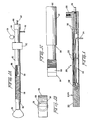
- a more detailed diagram of control electrode 200 is shown in Figure 6.
- a solid cylindrical electrode tip 204 is provided at one end of electrode 200.
- Tip 204 is constructed of molybdenum or graphite, depending upon the temperature of the bath which tip 204 must sustain.
- a hollow support pipe 206 is provided to hold electrode 204 in a desired position.
- a threaded stud 208 is provided at one end of support pipe 206 for attaching electrode tip 204 to support pipe. 206.
- An electrically conductive pipe cap 210 is provided at the opposite end of pipe 206.
- the interior of pipe 206 between threaded stud 208 and pipe cap 210 forms a hollow fluid-tight passage 212.
- An input coolant pipe 214 is inserted through a wall of pipe 206 and terminates in an interior passage 212. near the threaded stud 208.
- An exit path is provided from passage 212 through an exit pipe 216 positioned coincident with the longitudinal axis of pipe cap 210.
- circuit means 300 for energizing the primary electrode means 26, 28 and 30 with multiphase current and for time-sharing the multiphase current with the control electrode means 200.
- control circuit 300 which provides over lines 302, 304, and 306, three phase current to primary electrodes 26, 28 and 30 respectively.
- control circuit 300 operates to time-share the multiphase current supplied over lines 302, 304 and 306 with the control electrode 200 over line 308. More specifically, control circuit 300 operates to sequentially replace each primary electrodes 26, 28 and 30, with control electrode 200. When so replaced, the current intended for primary electrode 26, 28 or 30 instead passes through control electrode 200. This creates an electrically imbalanced load which causes generation of an additional current path from control electrode 200 to nozzle 18.
- This additional control path increases the temperature of product adjacent the additional current path in the vicinity of orifice 16.
- the control of current through this additional current path provides a vehicle for precisely regulating the temperature of produce adjacent orifice 16.
- the physical distance between conductive surface 220 at the end of control electrode 200 and orifice 16 also affects current flow adjacent orifice 16. The closer conductive surface 220 is to orifice 16, the greater the temperature of product 12 adjacent orifice 16 for a given amount of current. The distance between conductive surface 220 and orifice 16 is controlled by an output signal from control circuit 300 delivered over line 324 to motor 202.
- control circuit 300 governs the position of conductive surface 220 of control electrode 200 as a function of the temperature of the product 12 passing through orifice 16 as determined by temperature sensor 320, and/or as a function of the rate of flow of product 12 through orifice 16 as determined by the operation of load cell 326.
- a schematic diagram of control circuit 300 is provided in Figure 7.
- a multiphase power source 400 is shown coupled to a delta configuration multiphase transformer 402.
- Secondaries 404, 406, and 408 of power transformer 402 are connected in a wye configuration.
- the common point 409 of the wye configuration of secondaries 404, 406 and 408 is coupled by a line 410 to nozzle 18 to provide a return current path for current passing through control electrode 200.
- Variable position taps 412, 414, and 416 are coupled through switches 418, 420, and 422, respectively, to primary electrodes 26, 28, and 30. With switches 418, 420 and 422 in position A, secondaries 404, 406, 408 are coupled respectively to primary electrodes 26, 28, and 30.
- switches 418, 420 and 422 are illustratively shown to be double-throw, single-pole switches, they may in fact comprise portions of a high power SCR switching circuit such as the Hallman Model No. PA-1, which may be opened or closed depending upon the signals generated by a control unit 424 over lines 426, 428, and 430, respectively.
- a control unit 424 may open or closed depending upon the signals generated by a control unit 424 over lines 426, 428, and 430, respectively.
- Switches 418, 420 and 422 are shown in Figure 7 to have second positions B, in which position these switches connect secondaries 404, 406 and 408, respectively, to control electrode 200 through line 308.
- each switch 418, 420, and 422 is capable of electrically replacing primary electrodes 26, 28 and 30, respectively, with control electrode 200.
- switches 418, 420 and 422 are moved sequentially from position A to position B and returned to position A at zero cross-over points of the current appearing in secondaries 404, 406, and 408. These cross-over points may be determined by sensors 432, 434 and 436 which are electrically coupled to secondaries 402, 406, and 408, respectively.
- the substitutions may last for as long as a single cycle, or for several cycles, depending upon the amount of current necessary to be diverted to control electrode 200 to maintain the desired temperature as detected by temperature sensor 320, and/or the desired rate of flow as detected by load cell 326. As additional current is required, the amount of substitution by switches 418, 420 and 422 is increased by control unit 424. When the input from load cell 326, and temperature sensor 320 indicate that less current is required, the amount of substitution by switches 418, 420, and 422 is decreased.
- motor 202 may also be operated by a signal from control unit 424 over line 324 to move surface 220 of control electrode 200 closer to orifice 16, and in the converse, to move surface 220 further away when less temperature is required.
- the control unit 424 is also coupled by line 442 to nozzle coolant valve 24, and by line 444 to vessel coolant valves 124.
- nozzle coolant valve 24 controls the flow of coolant through cooling assembly 22 of nozzle support 20. More specifically, valve 24 controls the flow of fluid through pipes 66 and 70 in Figure 2.
- Vessel coolant valves 124 are illustratively shown in Figures 4A and 4B as governing the flow of coolant allowed into chambers 112, 114, 116, and 118 of vessel 10.
- nozzle coolant valve 24 permits the selective freezing of product in orifice 16 to close off and terminate the flow of product through nozzle 18, and the operation of vessel coolant valves 124 operate to help selectively position the pool of melted product 12 adjacent orifice 16.
- product 12 to be melted preferably minerals commonly referred to as fly ash
- product 12 to be melted preferably minerals commonly referred to as fly ash
- opening 14 in sufficient quantity to cover orifice 16, primary electrodes 26, 28 and 30, and control electrode 200.
- control electrode 200 is moved into a position whereby lower conductive surface 220 is immediately adjacent, but not touching, upper surface 44 of nozzle 18.
- switches 418, 420, 422 are operated to provide time-sharing of the current supplied to primary electrodes 26, 28 and 30 with control electrode 200. The amount of time-sharing is increased until the temperature between lower surface 220 of control electrode 200 and upper surface 44 of nozzle 18 is sufficient to melt product 12 adjacent orifice 16. As the melting process continues, nozzle control valve 24 is opened to provide coolant flow through pipes 66 and 70 of nozzle support 20 sufficient to assure that the pool of melted product 12 adjacent orifice 16 does not come in contact with nozzle support 20.
- conductive surface 220 of control electrode 200 may be withdrawn through operation of motor 202 from the upper surface 44 of nozzle 18 and the amount of time-sharing by control electrode 200 may be reduced through the operation of switches 418, 420 and 422.
- control electrode 200 When the pool of melted product 12 finally reaches conductive surfaces 182 of primary electrodes 26, 28 and 30, the operation of control electrode 200 may be temporarily suspended, and conductive surface 220 may even be moved even further from the upper surface 44 of nozzle 18. When the conductive pool reaches conductive surfaces 182 of primary electrode 26, 28 and 30, a low current between the primary electrodes 26, 28 and 30 may maintain that pool in a melted stated. If it is not desired to begin pouring operation, nozzle control valve 24 may be further opened to increase the cooling of nozzle support 20, and thereby solidified melted product 12 in channel 46 of nozzle 18 to plug nozzle 18 and prohibit additional flow of product 12 from the melted pool through nozzle 18.
- a pour operation may begin by moving control electrode 200 back toward nozzle 18, until conductive surface 220 of control electrode 200 is again immediately adjacent, but not touching, upper surface 44 of nozzle 18.
- the time-sharing process then commences, within time-sharing of current from secondaries 404, 406, and 408 with control electrode 200, until the intensity of current between control electrode 200 and nozzle 18 is sufficient to melt out the plug which had been formed in channel 46 of nozzle 18.
- conductive surface 220 of control electrode 200 is once again moved, back from upper surface 44 of nozzle 18, but remains at a position clearly closer to orifice 16 than either of primary electrodes 26, 28 or 30.
- conductive surface 220 is ideally positioned on the order of one-half of an inch from upper surface 44 in order to accomplish melting of product 12 solidified in channel 46, and is thereafter preferably positioned anywhere between one-half to three inches above upper surface 44 depending upon the desired pour rate, the conductivity of the product to be melted, the amount of current supplied by secondaries 404, 406 and 408, and the amount of time-sharing provided by switches 418, 420, and 422.
- Measurement by load cell 326 indicates a continuous weight of vessel 10 and product 12. With a known fixed amount of product 12 being continuously added to vessel 10, for example 40,000 Ibs per hour (18144 kg/h), a rate of flow of product 12 through orifice 16 less than 40,000 Ibs per hour will be evidenced by an increase in the reading of load cell 326, and a rate of flow greater than 40,000 Ibs per hour will be indicated by load cell 326 as a decrease in the overall weight of vessel 10 and product 12.
- Control circuit 300 must be set up to either increase the amount of time-sharing by control electrode 220 and/or decrease the amount of distance between conductive surface 220 of control electrode 200 and orifice 16 in the event load cell 326 indicates that the pour rate must be increased. A converse operation must occur through the operation of control circuit 300 in the event load cell 326 indicates that the pour rate must be decreased.
- temperature of melted product 12 passing through the orifice 16 is detected by temperature sensor 326, and used to control the operation of control circuit 300.
- the temperature of coolant passing through compartments 112,114,116, and 118 of vessel 10 may be continuously detected to determine the location of the melted pool formed by primary electrodes 26, 28 and 30. If, for example, the temperature of coolant exiting the compartment 114 on the extreme left-hand side of vessel 10 is warmer than the coolant exiting the compartment 118 on the right-hand side of vessel 10, this indicates that the pool of melted product is not directly centered over orifice 16, and instead has shifted to the left. To control the shift of the position of the pool of melted product 12, vessel cooling valves 426 are reset to increase the relative flow of coolant through the left-hand quadrant of vessel 10, and thereby shift the pool of melted product 12 back into a centered position over orifice 16.
- the present invention provides apparatus and methods for definitively controlling the temperature of product 12 immediately adjacent a product exit orifice 16 of a vessel 10, the flow rate of product 12 passing through that orifice 16, and the position of a pool of melted product 12 surrounding that orifice 16.
Landscapes
- Chemical & Material Sciences (AREA)
- Chemical Kinetics & Catalysis (AREA)
- Electrochemistry (AREA)
- Engineering & Computer Science (AREA)
- Materials Engineering (AREA)
- Organic Chemistry (AREA)
- Furnace Details (AREA)
- Glass Melting And Manufacturing (AREA)
- Manufacture, Treatment Of Glass Fibers (AREA)
- Vertical, Hearth, Or Arc Furnaces (AREA)
- Gasification And Melting Of Waste (AREA)
- Feeding, Discharge, Calcimining, Fusing, And Gas-Generation Devices (AREA)
Claims (23)
Priority Applications (1)
| Application Number | Priority Date | Filing Date | Title |
|---|---|---|---|
| AT81902096T ATE22434T1 (de) | 1981-06-26 | 1981-06-26 | Schmelzofenanlage und verfahren zum kontrollieren des schmelzens. |
Applications Claiming Priority (1)
| Application Number | Priority Date | Filing Date | Title |
|---|---|---|---|
| PCT/US1981/000878 WO1983000144A1 (fr) | 1981-06-26 | 1981-06-26 | Appareil de four electronique a haute temperature et procedes de fonctionnement |
Publications (3)
| Publication Number | Publication Date |
|---|---|
| EP0082143A1 EP0082143A1 (fr) | 1983-06-29 |
| EP0082143A4 EP0082143A4 (fr) | 1983-09-26 |
| EP0082143B1 true EP0082143B1 (fr) | 1986-09-24 |
Family
ID=22161303
Family Applications (1)
| Application Number | Title | Priority Date | Filing Date |
|---|---|---|---|
| EP81902096A Expired EP0082143B1 (fr) | 1981-06-26 | 1981-06-26 | Four de fusion et procédé pour contrôler la fusion |
Country Status (5)
| Country | Link |
|---|---|
| EP (1) | EP0082143B1 (fr) |
| JP (1) | JPS58501031A (fr) |
| AT (1) | ATE22434T1 (fr) |
| DE (1) | DE3175374D1 (fr) |
| WO (1) | WO1983000144A1 (fr) |
Families Citing this family (1)
| Publication number | Priority date | Publication date | Assignee | Title |
|---|---|---|---|---|
| EP0372111B1 (fr) * | 1988-12-07 | 1994-09-07 | BETEILIGUNGEN SORG GMBH & CO. KG | Electrode pour un four de fusion du verre |
Family Cites Families (7)
| Publication number | Priority date | Publication date | Assignee | Title |
|---|---|---|---|---|
| US3109045A (en) * | 1958-03-03 | 1963-10-29 | Owens Illinois Glass Co | Electrically heated glass melting unit |
| FR1309678A (fr) * | 1961-02-17 | 1962-11-16 | Siemens Ag | Dispositif d'alimentation ou distributeur à poinçon, non refroidi, pour cuves ou bassins de fusion |
| DE1232705B (de) * | 1961-02-17 | 1967-01-19 | Siemens Ag | Speiservorrichtung fuer Schmelzwannen zum Schmelzen von silikatischen Materialien |
| FR1482084A (fr) * | 1966-03-25 | 1967-05-26 | Four électrique perfectionné de fusion à très haute température | |
| FR2029840A5 (fr) * | 1969-01-28 | 1970-10-23 | Clerc De Bussy Le | |
| FR2054464B1 (fr) * | 1969-07-07 | 1974-06-14 | Commissariat Energie Atomique | |
| US4017294A (en) * | 1974-07-25 | 1977-04-12 | Johns-Manville Corporation | Furnace outlet |
-
1981
- 1981-06-26 WO PCT/US1981/000878 patent/WO1983000144A1/fr not_active Ceased
- 1981-06-26 DE DE8181902096T patent/DE3175374D1/de not_active Expired
- 1981-06-26 JP JP50251881A patent/JPS58501031A/ja active Granted
- 1981-06-26 AT AT81902096T patent/ATE22434T1/de not_active IP Right Cessation
- 1981-06-26 EP EP81902096A patent/EP0082143B1/fr not_active Expired
Also Published As
| Publication number | Publication date |
|---|---|
| EP0082143A1 (fr) | 1983-06-29 |
| WO1983000144A1 (fr) | 1983-01-20 |
| JPS58501031A (ja) | 1983-06-30 |
| ATE22434T1 (de) | 1986-10-15 |
| JPS64329B2 (fr) | 1989-01-06 |
| DE3175374D1 (en) | 1986-10-30 |
| EP0082143A4 (fr) | 1983-09-26 |
Similar Documents
| Publication | Publication Date | Title |
|---|---|---|
| US4399544A (en) | High temperature electronic furnace apparatus and methods of operation | |
| US4486211A (en) | Apparatus and methods of operation for converting fly ash into high quality mineral wool | |
| EP0060691A1 (fr) | Contruction d'un four électrique | |
| US2754346A (en) | Glass melting furnace | |
| US4450570A (en) | Vacuum arc melting and casting furnace with a vacuum chamber and a tilting crucible | |
| JP2738423B2 (ja) | ガラス用電熱熔融炉 | |
| US3429972A (en) | Very high temperature electric melting furnace | |
| US3502847A (en) | Apparatus for heating the heads of ingot moulds or the gates of casting moulds | |
| US2280101A (en) | Electric furnace and melting method | |
| CA1153409A (fr) | Fours electriques | |
| US4675878A (en) | Method and device for the melting and heating of materials | |
| US2707720A (en) | Electromagnetic valve | |
| US4504544A (en) | High quality mineral wool | |
| CA1185305A (fr) | Four electronique haute temperature, et mode d'exploitation connexe | |
| EP0082143A4 (fr) | Four de fusion et procédé pour contrÔler la fusion. | |
| AU7414781A (en) | High temperature electronic furnace apparatus and methods of operation | |
| EP0124490A1 (fr) | Fond conducteur pour four à arc à courant direct | |
| US1069923A (en) | Electric furnace. | |
| MXPA01012414A (es) | Procedimiento y dispositivo para el funcionamiento de hornos de fundido por arco electrico y/o hornos de fundido por resistencia. | |
| US3997316A (en) | Use of crossed electrode pairs in a glassmaking furnace | |
| US4592066A (en) | Conductive bottom for direct current electric arc furnaces | |
| RU2786734C1 (ru) | Устройство для внепечной обработки металла в ковше | |
| US3108151A (en) | Electric furnace | |
| US1418030A (en) | Electrically-heated furnace | |
| SU1242549A2 (ru) | Способ набивки угольной массой швов подины электролизера |
Legal Events
| Date | Code | Title | Description |
|---|---|---|---|
| PUAI | Public reference made under article 153(3) epc to a published international application that has entered the european phase |
Free format text: ORIGINAL CODE: 0009012 |
|
| AK | Designated contracting states |
Kind code of ref document: A1 Designated state(s): AT CH DE FR GB LI LU NL SE |
|
| 17P | Request for examination filed |
Effective date: 19830718 |
|
| GRAA | (expected) grant |
Free format text: ORIGINAL CODE: 0009210 |
|
| AK | Designated contracting states |
Kind code of ref document: B1 Designated state(s): AT CH DE FR GB LI LU NL SE |
|
| PG25 | Lapsed in a contracting state [announced via postgrant information from national office to epo] |
Ref country code: NL Effective date: 19860924 Ref country code: LI Effective date: 19860924 Ref country code: FR Free format text: THE PATENT HAS BEEN ANNULLED BY A DECISION OF A NATIONAL AUTHORITY Effective date: 19860924 Ref country code: CH Effective date: 19860924 Ref country code: AT Effective date: 19860924 |
|
| REF | Corresponds to: |
Ref document number: 22434 Country of ref document: AT Date of ref document: 19861015 Kind code of ref document: T |
|
| PG25 | Lapsed in a contracting state [announced via postgrant information from national office to epo] |
Ref country code: SE Effective date: 19860930 |
|
| REF | Corresponds to: |
Ref document number: 3175374 Country of ref document: DE Date of ref document: 19861030 |
|
| REG | Reference to a national code |
Ref country code: CH Ref legal event code: PL |
|
| EN | Fr: translation not filed | ||
| NLV1 | Nl: lapsed or annulled due to failure to fulfill the requirements of art. 29p and 29m of the patents act | ||
| PG25 | Lapsed in a contracting state [announced via postgrant information from national office to epo] |
Ref country code: LU Free format text: LAPSE BECAUSE OF NON-PAYMENT OF DUE FEES Effective date: 19870630 |
|
| PLBE | No opposition filed within time limit |
Free format text: ORIGINAL CODE: 0009261 |
|
| STAA | Information on the status of an ep patent application or granted ep patent |
Free format text: STATUS: NO OPPOSITION FILED WITHIN TIME LIMIT |
|
| 26N | No opposition filed | ||
| PGFP | Annual fee paid to national office [announced via postgrant information from national office to epo] |
Ref country code: DE Payment date: 19920515 Year of fee payment: 12 |
|
| PGFP | Annual fee paid to national office [announced via postgrant information from national office to epo] |
Ref country code: GB Payment date: 19920529 Year of fee payment: 12 |
|
| PG25 | Lapsed in a contracting state [announced via postgrant information from national office to epo] |
Ref country code: GB Effective date: 19930626 |
|
| GBPC | Gb: european patent ceased through non-payment of renewal fee |
Effective date: 19930626 |
|
| PG25 | Lapsed in a contracting state [announced via postgrant information from national office to epo] |
Ref country code: DE Effective date: 19940301 |